In every meshing log there is no error, but all simluations broke up.
It appends this message:
“The solution diverged, most likely due to presence of bad elements in the mesh. Such elements tend to exist near walls and sharp corners. Visually inspect your mesh to locate them and re-mesh with additional refinements in their vicinity. If you are confident about the mesh-quality, please reduce relaxation factors and use more conservative numerical schemes.”
At Run1 i used the Mesh2 and at Run2 the Mesh3 with the same simulation settings.
How can i find the error ?
Then, although I am not familiar with Multiphase meshes, to me your mesh is pretty course, at least try some edge refinement to sharpen your edges. Sometimes too coarse a mesh can pose problems like too fine ones…
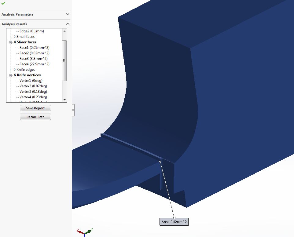
the area located in the above image was too bad (too many knife-edges, 4 faces) and this area creates a problem for your simulation.
clear this area first.
your end time was too large. I think to reduce end time or delta or increase run time to avoid runtime problem also increase no of the processor(16).
@ROHIT_SR,
Which programm did you use for the mesh analysis ?
Is it possbile with simscale ?
I uploadet the edited model again. I did the meshing and the simulation set up all over again, and it works ?!
At the first project, no simulation started, the all broke up at 0 %.
Now are a few succesfully
I make three meshes:
Mesh 1 21.4k cells
Mesh 2 165.4k cells
Mesh 3 4.4M cells
and seven Runs:
Run 1 Mesh 1: ok
Run 2 Mesh 2: ok
Run 3 Mesh 2 symmetry (symmetry boundary condition at one wall): ok
Run 4 Mesh 3 symmetry: runtime exceeded
Run 5 Mesh 3 symmetry subdomain (subdomain with alphaphase1 (water) at the inlet, to rise the waterlevel quicker): diverged
Run 6 Mesh 3 symmetry: i canceled it, very slow
Run 7 Mesh 2 symmetry subdomain: i canceled it, the solver diverged at ~ 100 seconds of sim time
The first question: I did not know, why Run 5 did not run and Run 7 with the identical options run up to 100 seconds, with a coarser mesh ?
The second: Why did Run 7 broke up at ~ 100 seconds, i dont find a reason ?
The third:
This is my simulation reason.
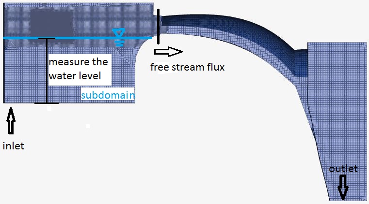
I like to mesasure the height of the waterlevel in dependency to the flux.
I have to measure the waterlevel in a distance to the weir, and it would be nice to have it in centimetres. So the Z axes of the cells at the measuring point has to be <1 cm. If the Z axes are longer a exact mesurement is not possible or ? This is the reason for the the region refinments.
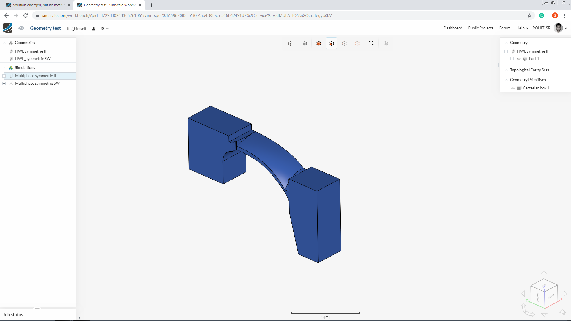
Not to lose the overview, i make a now projekt. With two geometrys.
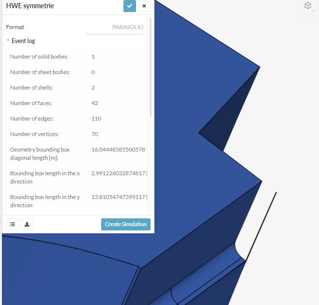
I check my geometry manuelly in the simscale view, and i dont find any small surfaces or other stuff.
I made two multiphase simulation, with identical options.
Mine geometry diverged, yours not …
Best regards
Kai
edit:
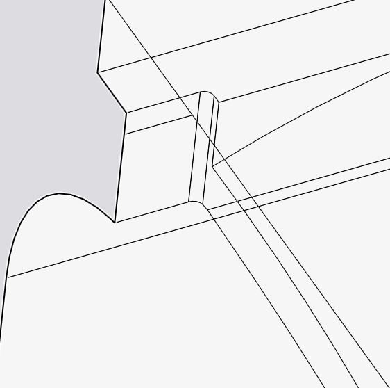
There’s a difference between these models, i made a round corner.
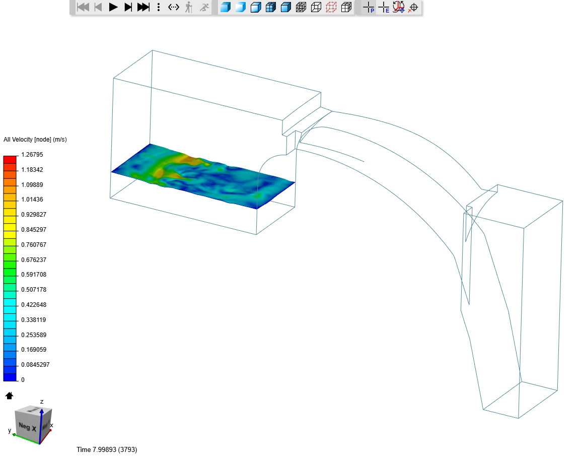
I was playing with the boundary conditions and water level at the beginning of the simulation on a mesh of my own, and I realised that the problem starts as soon as the water starts crossing the arch.
One of the tests—Run 8—was with the empty tank and completed the 20-second simulation without any problems. The approximate volume before overflowing is about 31 cubic meters; and since we are introducing water at the rate of 1 cubic meter per second (A_i \mathbf{v}_z), we would not have reached overflowing yet.
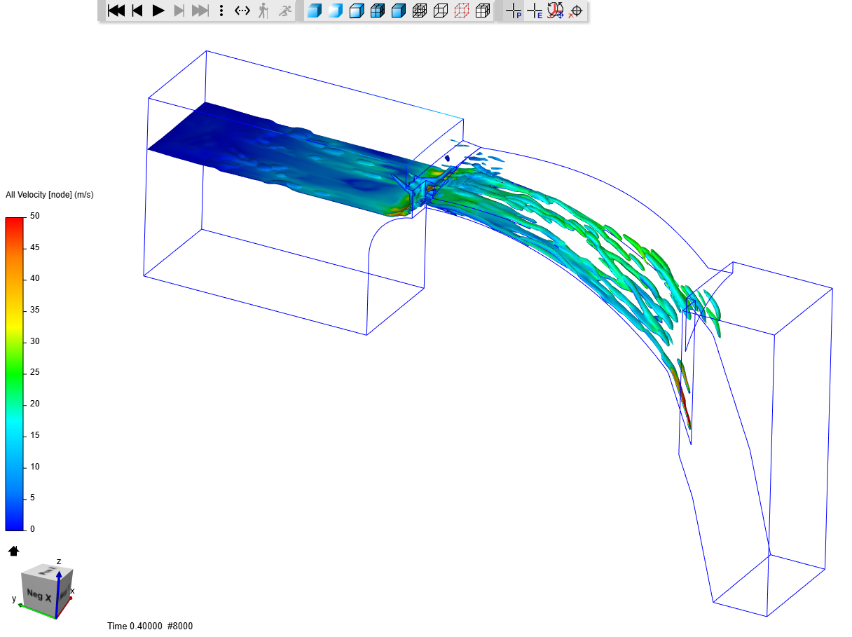
Having checked that the filling is correct, I focused on the arc part of the simulation. And for this I have also done some tests on a local machine, since it allows me a little more flexibility when it comes to controlling the simulation on the fly. In any case, one of the things I’ve seen and can be seen in the simulation is that the water crosses the arc at a very high speed (> 50 m/s), which is bad for Courant, and for the air around there (no-slip condition at water-air interface).
Since the speed is very high—is that what you were expecting —the time step has to be reduced a lot to keep Courant low. In some of the simulations that have failed in my machine, the time step has become of the order of 1e-80 s (could be a bug). So I tried to disable the automatic adjustment, setting a time step of 0.0001 s which gives me a Courant between 0.3 and 0.6. Sometimes I have temporarily reduced the time step to half, to keep the Courant number in that range, and it seems to have worked. So, to try that approach in SimScale, I specified a time step of 0.00005 s (on the safe side) for Run 15, which at the time of writing seems to be running fine.
Do the numbers make sense? Let’s see:
Inlet area: 2 m^2
Inlet velocity: 0.5 m/s
Inlet flow rate: 1 m^3/s
Outlet area: 1.8 m x 5 to 10 mm (assumption of water layer thickness)
Conservation of mass
Outlet velocity: 114 to 55 m/s (depending on water layer thickness)
So, unless I’m mistaken, results seem to make sense.
You can have a look at my copy of the project here.
Note that due to the smaller time step I limited the total run to just 2 seconds. Intending to run the whole 100 s might consume all your quota.
BONUS
In the local simulation I specified a wall were your velocity outlet was.
I cannot visually compare your two meshes without copying the project. But if mesh of Run 7 was coarser as you say, then respecting the maximum Courant number could be accomplished with a larger time step. This might be less problematic for the solver. Also, the coarser mesh could be affecting the estimation of the water thickness layer, so that a slower thicker layer of water is crossing the arch (you know, mass conservation). Additionally, the quality of the mesh can play a role.
A possible reason you can find in my previous post. The fact that your mesh was coarser could imply an estimation of a slower thicker water layer delaying simulation crash to a later stage. A more precise explanation would require a more detailed analysis of the simulation. But it occurs to me, too, that you may not be evacuating enough water through the outlet. It should be checked, because velocity outlet is less than half of velocity inlet and water might be accumulating or the arch inlet chocking.
Tonight I remembered a simulation of the Dyson fan that I did some years ago, when I was still starting on CFD and had little experience, I remember that I also got excessively high speed values with a jet that extended almost to the end of the domain without any alteration. That was because I was modeling the flow as laminar when we were actually in a turbulent regime. The problem was solved once I activated turbulence in the model.
In this case exactly the same thing could be happening, as the flow at the inlet is clearly turbulent (Re > 500 000). Therefore, I have launched another simulation by activating the k-epsilon model. I hope that now part of the momentum of the flow dissipates, there is some more circulation in the pond and we can see some surface tension acting at the entrance of the arc avoiding that the flow overflows at such speed.
So, try enabling turbulence in your models and let us know if you see any improvement.
No, 50 m/s is far too much, here is a video from youtube. It shows a similar overflow spillway, but only the backside. Spillway
ok, i will try turbulence in my model and furthermore i increase the outlet speed and report back.
The 100 s sim time, are only estimated, i need steady stade for my measurement, maybe i also start with 2 seconds
PS: And the time step to 0.00005
Best regards
Kai
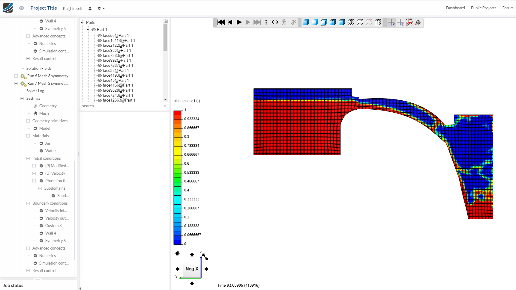
Good evening,
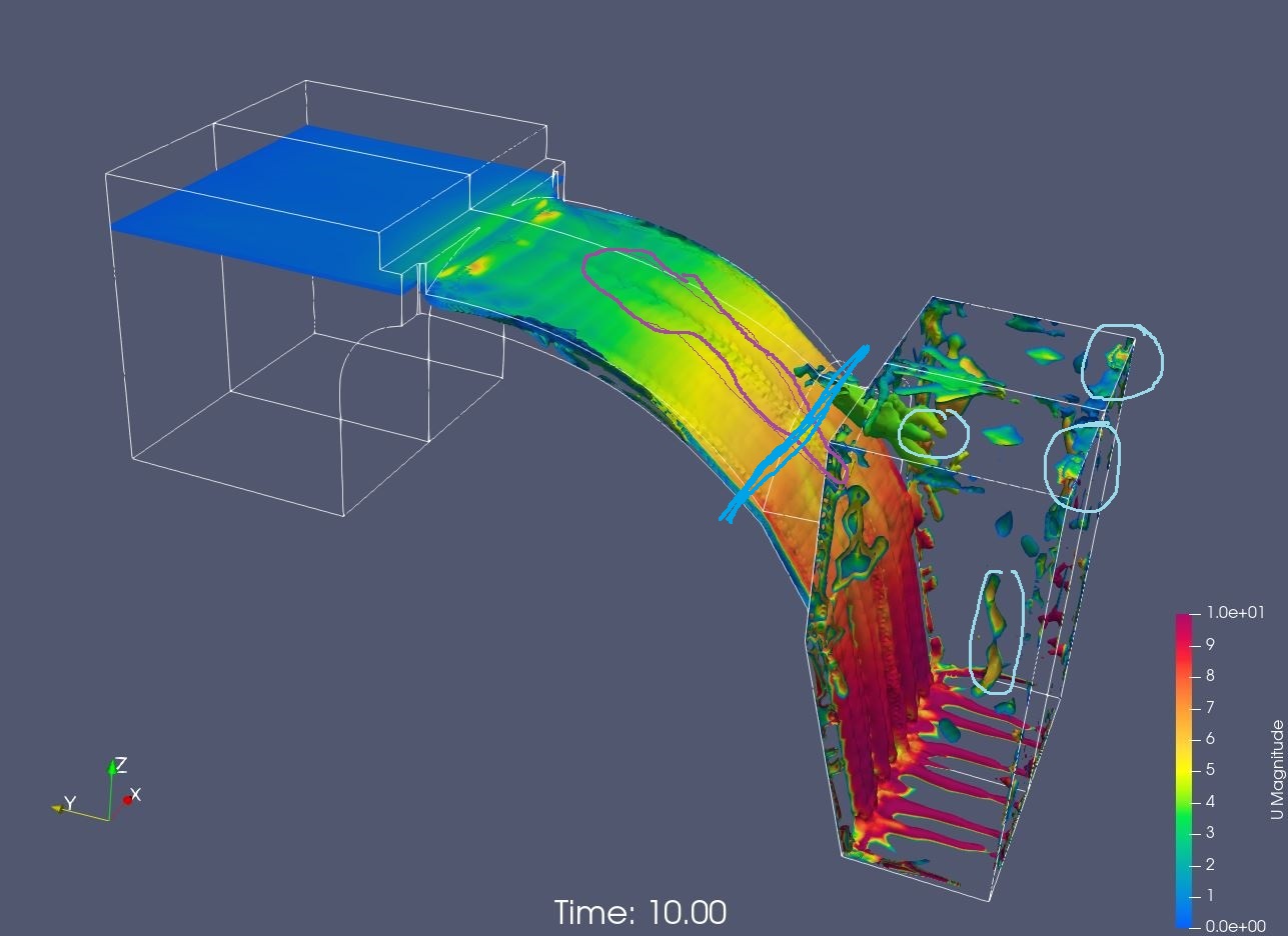
the simulations with the turbulence model (k omega SST) were a success !
I simulate 2 sec, 5 sec and 10 sec succesfully.
Here is a movie from the 10 seconds run.
Like you said, it takes very long to calculate, 10 seconds, 880 min and 234 core hours.
I make a Chart, with the timestep difference, in the first second the delta t is very big. Suddently it drops to 2,0E-04 and stay in this area. I think this behavior is normal ? More water and waterarea are need more time to calculate ?
I have a few more question, but they dont really fit the subject.
To increase the calulcation speed, my i can cut the geometry at the blue line, with a velocity outlet with high speed ?
Awesome. It’s great to see that simulation is running ok.
For the outlet, you could define a custom zeroGradient for all variables. This way you ensure that the flow leaves the outlet as soon as it gets there.
I’m also trying with other boundary condition combinations. Will let you know if I find a successful one.
Cheers,
PS: I requested the activation of an inlet boundary condition specific to multiphase flows that could be useful in this project. You can vote here