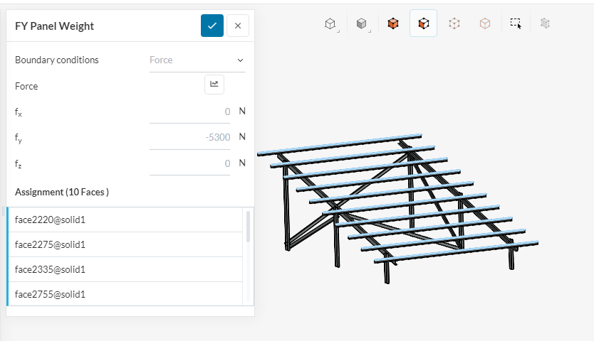
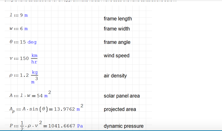
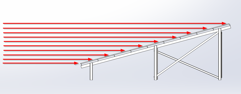
I have not done a CFD analysis (although this is certainly possible). I used basic hand calculations to determine the wind loading. The loading in the z-direction is due to wind while loading in the y-direction is due to the self-weight of the solar panels (just a guess, you can use the correct value).
You should have no concerns about the accuracy of SimScale. It uses the CodeAster solver which has been thoroughly tested and is used by many commercial companies and research organisations. The difference between SimScale and any other FEA package is not a question of accuracy but features and price. In my opinion, SimScale offers a lot of features for the price!
As with any FEA package, the accuracy of your results is heavily dependant on how well you set it up. A poorly setup simulation will produce inaccurate results. The quality of your setup plays a much bigger role in the accuracy of your results than the brand of software you use.
I am getting very bad results because apparently my CAD file is not clean enough. So is it possible for someone to clean up the CAD File for me or help me in performing CFD successfully ? @BenLewis@jousefm@Retsam ?
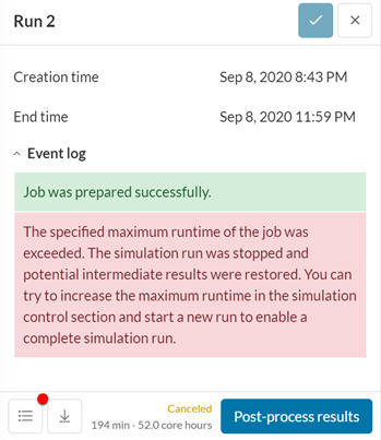
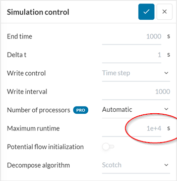
You could try increasing the maximum runtime or simplifying your simulation setup.
I’m not a CFD expert, but it looks to me like you could significantly reduce the size of your domain without impacting the accuracy of results.
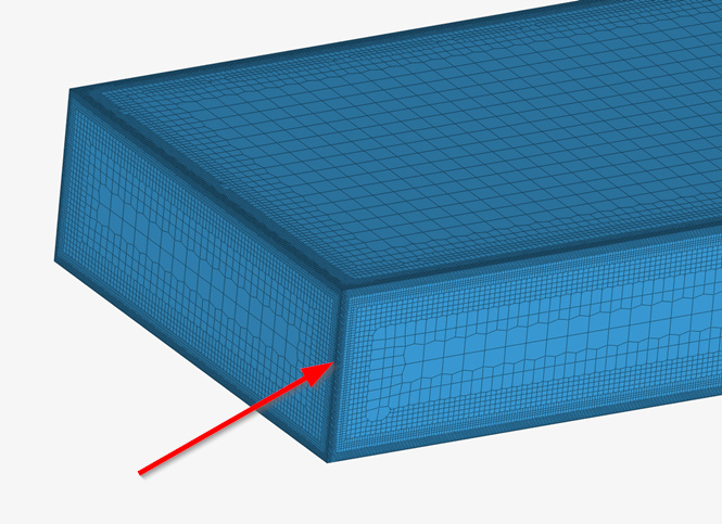
Also, it looks like you have a fine mesh on the edges of your bounding box which will significantly increase your computation time without adding any value.
ok @Retsam please check this link as well and let me know. I have cleaned up the geometry but when I am performing CFD, I am again getting very bad results.
Hi @BenLewis . I wanted to know that how did you calculate -5300 N as weight. How many panels did you consider and what was the weight of each panel? I mean what do we have to consider to incorporate the total weight ?
Another thing I wanted to ask was that if the material of the structure is mild steel , even then should I select steel from the materials library ?
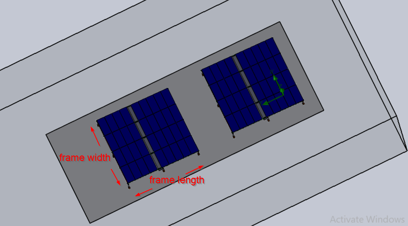
@BenLewis another thing I wanted to ask was that how did you calculate the frame length and frame width? Is it the total size of all the panels or is it just one panel?
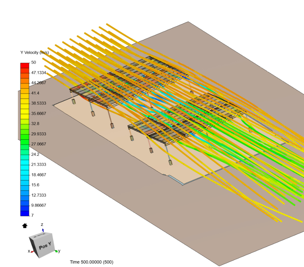
I did prepare a simple CFD simulation of your solar panels geometry (umer), using 150 km/h wind. Please first read that statement, which is pessimistic one, about possibility to finish any project / simulation FAE / CFD with your current involvement. Your Simscale reading time counter is now around 4 hours, from June 2020 to now (3 months). With that pace, (you would need perhaps 40 - 80 hours of reading documentation and about 2000 core-hours of simulation) you could be understanding a bit what you are doing in 6 - 12 months. This is your choice.
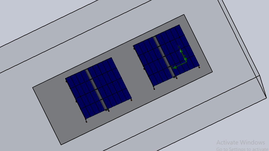
Your current CFD simulation is based on ‘umer’ geometry, containing 72 solar panels in two sets. Mesh you produced is about 30 Mcells, which is not much too big. Your simulation domain has 0.5 km length and you ignored Ben advice about reducing it.
As an example, I created Test4Panels project from ‘umer’ geometry and did the following ‘accommodations’:
Domain size volume reduced ~100 times.
Mesh: Hex-dominant parametric (IncompressibleMid > Mesh 2), size 2.7 Mcells, creation time 10 core-hours. Simulation IncompressbleBig contains Mesh 1, 12 Mcells, with correct beam meshing, but it is not really relevant for main forces on panels.
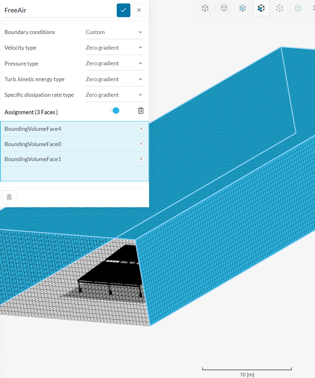
BC for domain simulates ‘free air’ (no wind tunnel, which should be much bigger), with ‘zero gradient’ BC.
Simulation: Foam initialization set to ‘on’, initial run time set to 500 steps. It took 25 core-hours.
Simulation did not converge: it would need another 500 steps (at least), but reported forces are already stable.
Forces were gathered only on top of panels (upper side), you need to set botom panel sides to account for low pressure generated by flow.
Solution fields of simulation ‘Run 1’ will give you already interesting insights. Learning how to visualize different values is also a long adventure.
Results can be read from Force plots and Area averages. Pressure moments should be ignored, as I did not know the correct reference for your set of panels (Center of rotation). You should find from your CAD program correct points.
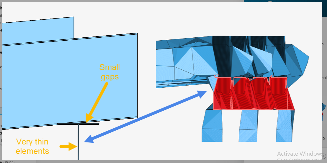
Here is the mesh with ‘free air’ BC set (Zero Gradient):
The example structure I gave had a mounting area of 6 m by 9 m. This is large enough to hold an array of 27 solar panels (based on the dimensions of the solar panels in your original model).
I guessed that each panel might weigh 20 kg. Therefore, the total load imposed on the structure from the weight of the panels is:
27 panels x 20 kg x 9.81 m/s^2 = 5297 N. I used the rounded number of 5300 N.
You will need to adjust this value to take into account the actual weight of the solar panels you are using.
The material properties that we are concerned with in a linear study are the elastic modulus, Poisson’s ratio and density. These values do not change much from one steel type to another. So you can use the generic steel material type for all steels.
What does change is the yield strength of the material. You need to know this value so that you know what value of stress is acceptable within your structure.
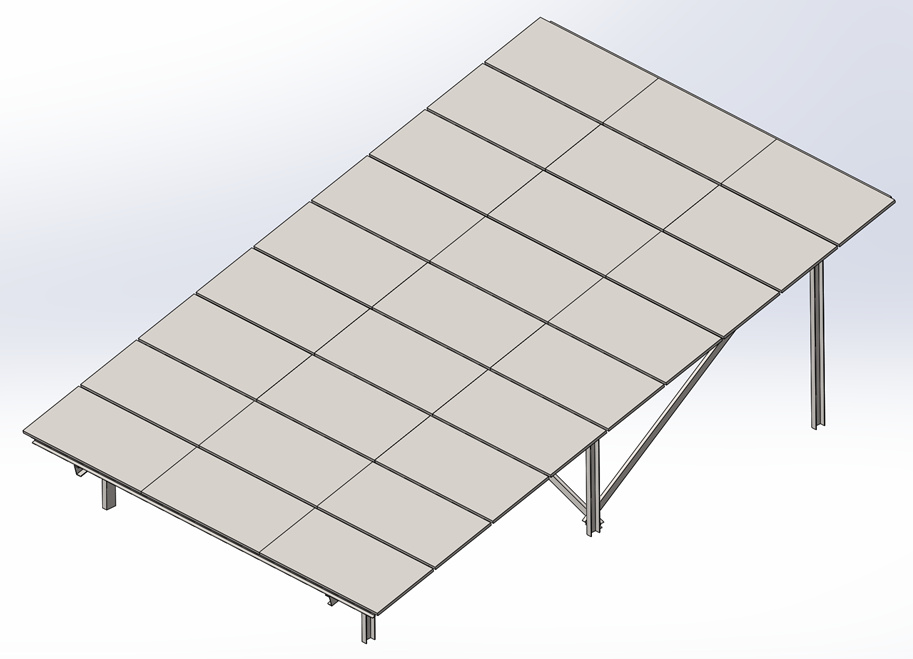
The example frame I gave was based on your original dimensions. I just reconfigured the structure so that it would be easier to manufacture and added diagonal bracing for stability.
ok thanks alot @BenLewis. One thing I wanted to ask was that can you give the reference of these calculations ? Are these calculations taken from AESC standards ?
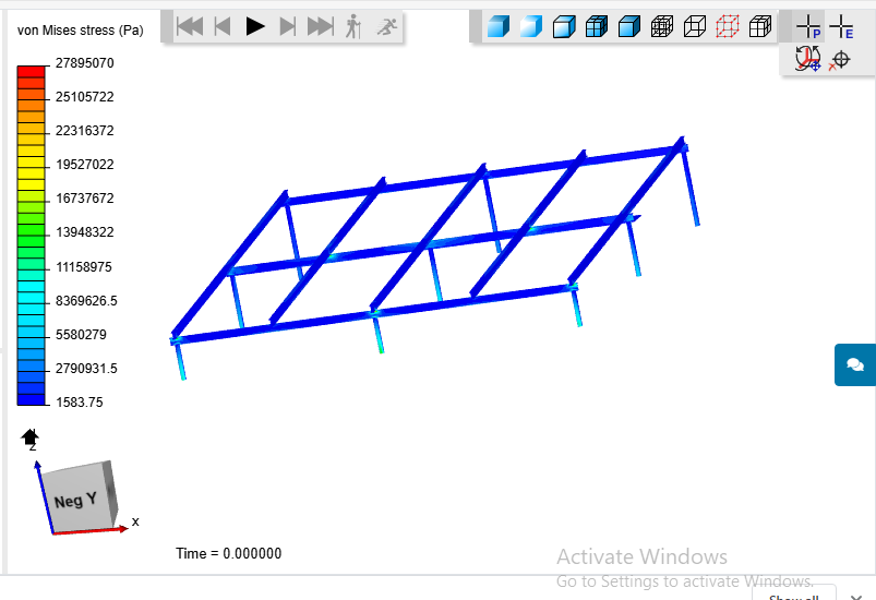
One more thing @BenLewis. I am getting my vonmises stress of a structure something like this. Putting material as steel. So the colour appearing is all blue. I wanted to ask if results like this are physically possible ? I can hardly see any yellow or red or green colour
@BenLewis I wanted to ask one more thing. This is the structure which I have to analyse. I wanted to ask that which area should I consider for frame length and frame width? Can you mark in this picture?
Hi @alijalil, I cannot find this simulation in your public projects, so it is impossible for me to say whether these results are realistic or not. In general, if your loads are weak in comparison to the strength of your structure then the resulting stress will be low.
Please keep in mind that the colours are automatically scaled to the stress range in your model. So red is not necessarily bad and blue is not necessarily good. They are just the maximum and minimum stresses found in your model. It is up to you, as the designer, to determine what is an acceptable level of stress in the material you are using.
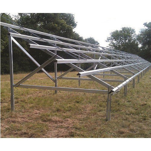
As a guide, below is an image of a solar panel frame I found on the internet. It looks like it is make of a much lighter gauge material then what you have modelled. So the low stresses you are seeing in you model may be realistic.
The area that is important here is the area of the structure that is perpendicular to the wind. So if the solar panels are flat, it is just the area of the front edge. On the other hand, if the solar panels are vertical it is the full area of the front face. In your case, the solar panels are inclined at an angle, so it is the area of the front face that is exposed to the wind.