Hello friends
My intent to identify the short circuit of flow between an intake louver and exhaust louver.
In this model, I set out an exhaust air duct connecting to an outdoor environment(a 50m x 50m big square)
The fresh air louver(velocity outlet) is right under the exhaust louver(velocity inlet), 1m apart from each other.
For the big square, I set some of the faces as pressure outlets.
Is it the correct setup to mimic the outdoor environment?
Hi , this is Fillia!
I have not simulated a louver application in the past, however what I would consider is to change the faces of the open air environment to Natural convection inlet/outlet instead of Pressure Outlet, like in this project: Inconsistent post-process result
this website says that when velocity inlet is used, at least 1 pressure outlet should be placed.
So can Natural convection inlet/outlet replace pressure outlet?
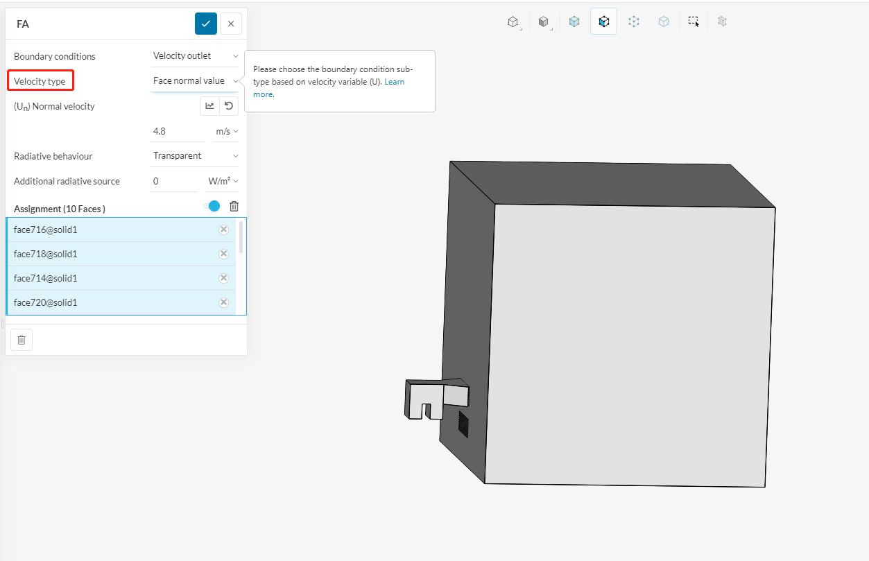
Meanwhile, i set a velocity outlet, which have the same size as velocity inlet.
But the flow pattern of velocity outlet is not as obvious as the inlet.
What if i change the “velocity type”?
You can have a natural convection inlet/outlet instead of a pressure outlet-or pressure inlet-.
And of course you can use another type of velocity outlet if you want to. Flow rate can be used to control this as well