For my analysis “sideways moving spring” I want to create a physical contact between the spring and the outer two panels. However, when trying to do this I get the following message “Error: The type of at least one contact is not applicable for the specified contact properties.”. Does anyone know what this error means and how I can solve it? I’ve meshed all components using the standard meshing, i.e. tetrahedral automatic (fine mesh). Furthermore, is it possible to create normal contacts between the components without any errors?
This message appears if you have inconsistency in your local and global physical contact settings. For example, if you have selected Augmented Lagrange in the global settings then this error will pop up if you are using Friction or Frictionless Penalty for local settings where you normally define master and slave and vice versa.
Same error will appear if you have turned on the friction globally i.e. set to Coulomb and then use either Frictionless penalty or Frictionless augmented under local settings and vice versa.
I hope this helps. If you are still stuck, don’t hesitate to ask.
Thanks a lot for the help! I managed to run the analysis using physical contacts, but this time I’m running into trouble with convergence I’ve already updated some items, such as Tolerance of the convergence criteria (0.001 --> 0.01), Maximum Newton Iterations (15 --> 30), Reactualisation every nth increment (kept equal to 1) and Timestep definition (kept equal to manual). But unfortunately I still get an error after a while (Newton Convergevence could not be reached).
I don’t have experience with selecting the right values for the above settings, but do you maybe (or somebody else) now wht proper guidelines are to do this properly? Or should I change something else in the model (e.g. use more refined mesh)?
Thanks a lot for the help! Eventually, I managed to define the physical contacts Unfortunately, I have some issues now with convergence of the solution. I’ve moved the questions about this to another topic “Master and Slaves” as I believe it better fits in this discussion?
Hi @jvarkevisser - let’s keep the discussion on this post if that’s ok Since it is directly related to the Sideways Moving Spring topic. Can you move your posts here again?
My colleague @ahmedhussain18 is working on it and will get back to you soon!
Sorry for moving the posts, I’ve put it back in this thread
Hi Anna/Ahmed,
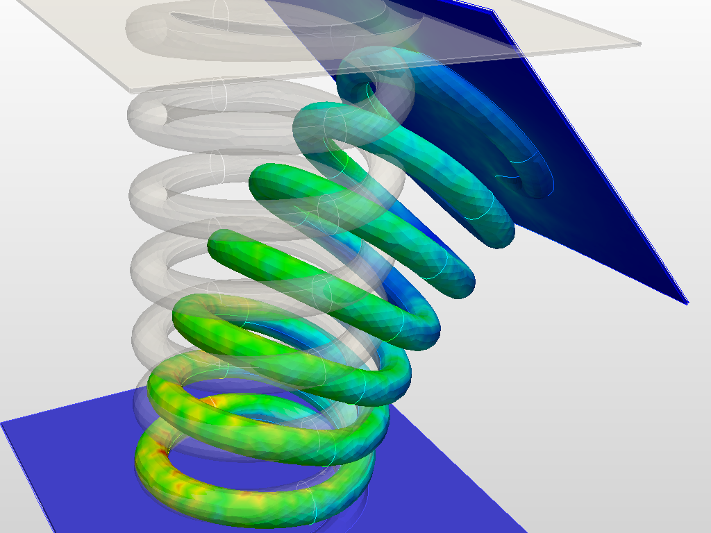
Thanks for the usefull tips about master and slave assignments! At the moment I’m working on an analysis involving a spring that is clamped between two plates (see link to project below):
Initially I want to see how the spring behaves in case one of the plates compresses the spring (and the other plate is fixed).
Secondly, I want to apply an additional (small) sideways movement on the compressive plate and see again how the spring behaves (how it rotates, deforms and how the contact areas are changing).
I’ve setup physical contacts between the spring (slave) and plates (master), but unfortunately I’m getting convergence issues after a while. I’ve already updated some items, such as Tolerance of the convergence criteria (0.001 → 0.01), Maximum Newton Iterations (15 → 45), Reactualisation every nth increment (kept equal to 1) and Timestep definition (kept equal to automatic). But unfortunately I still get an error after a while (Newton Convergevence could not be reached).
I don’t have experience with selecting the right values for the above settings, but do you maybe now what proper guidelines are to do this properly? Or should I maybe change something else in the model (e.g. use more refined mesh, modify constraints)?
I saw your case. I did also couple of runs with it. You really don’t need physical contact I think. The bonded contact will work for you in this case. What I did is that I merged all solids so that I even don’t have to give bonded contact.
The physical contact doesn’t make any difference though. It may make sense when you have a soft spring and due to high compression the sides of the springs touches the above and lower plate. But for that one have to be careful in assigning the master and slave for both contact cases.
I did three cases:
Simple compression via displacement (no physical contact required).
With simple pressure and allowing the above plate to move in any direction (physical contact required due to bending. But with the fused geometry, it’s not possible. One have to do it with the non-fused one)
With follower pressure (It follows the deformation and remains always normal to the surface. Thus giving the same deformation behavior as in 1st case)
For the second case, one can try the non-fused model with physical contact but it will be hard to converge with these such a nonlinearity. You can have a look at the project here: Sideways moving spring - SimScale
Unfortunately though, I’m afraid that the above approach won’t fully the answer my overall question (sorry for not being complete about this, I wasn’t aware you were actually trying to solve the complete problem yourself );
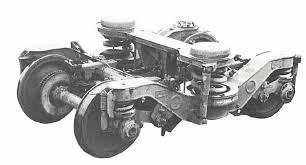
As a challenging excercise I wanted to model the behaviour of a spring that can be found in the bogie of a train, due to a sideway movement of the train cabin (e.g. when driving through a shunt).
As can be seen in the figure below the two large springs are positioned between the bogie frame and a so-called bolster beam (on which the cabin is resting on). The springs are not directly connected to these neighbouring structures (e.g. by means of a welt or bolts), but will be kept in position by means of the heavy cabin weight and friction between the components. In case the cabin will move sideways, also the bolster beam + topside of the springs will move sideways. So, besides being compressed the springs will also start to rotate/deform.
As I’m interested how the springs will rotate/deform and how the load/stress distribution will change at the connection between the springs and neighbouring structures I’ve created this simplified FEM model. Based on the above situation I believe:
I need to use physical contacts between the spring and plates
I (eventually) need to apply a small sideways movement to the upper plate (assuming for the moment that the rotation of the bolster beam can be ignored), while keeping the other plate fixed.
I’ve setup the model, but as pointed out before I get convergence issues when running the simulation. Do you think that the model should be solvable (or will it be to complex in terms of non-linear effects, etc.)? And if so, do you maybe have any guidelines how to prevent convergence issues (what would be reasonable choice for mesh, settings)?
I actually think that the second case you’ve described above almost resembles the one I’m thinking about, with the exception that the top plate is not free to move in any direction; I want to keep the top plate parallel with respect to the bottom plate (i.e. no rotation of the top plate) and apply a small sideways movement. What eventually may happen is that the contact between the spring and plates might come loose at some point (at least that’s what I think) and a redistribution of the loads/stresses at the spring-plate connections might occur.
I’ve checked your second case in your model, but couldn’t find any physical contacts? Was the setup of this case maybe overwritten by case 3? Is it possible to show the setup of this case 2 again?
I got your complete point. So there are certain things you can do:
You have to start with your initial model with three solids.
If the thickness of your plate doesn’t matter in this case, which I presume not since you want to make them rigid and only interested in seeing the stresses in spring. Then make them thick enough so you can make a coarse mesh on them as much as possible i.e. may be consisting of one or two elements. You can have a look at this project to see how it can be done: Mobile Drop Please focus on the coarseness of the floor in this case. Please note that it only make sense if you make those plates rigid.
You don’t need bonded contact in this case. You only need physical contact. Therefore, you have to make two physical contacts for top and bottom connection making sure that master in both cases are the plates.
Next you have to fix the bottom plate completely and make the top plate to move only in pressure direction i.e. Fixed value constraint with y=z=0 and x=unconstrained.
Then you have to apply an elastic support to the spring due to the fact that initially it is free to move. I would suggest to apply this elastic support on one of the middle face or on top and bottom edges. This elastic support actually will hold the spring with small springs. Thus restricting the rigid body motion which could have happened initially. The value of spring stiffness should have to be low enough so that it didn’t effect the overall results. Try to go with a bigger value first and run the simulation only for first iteration to see if it converges. Then start decreasing it 10 times and keep on running new runs until it fails. In this case you have to make sure that in details of Equation solver under Numerics, Stop if singular is set to false since the first iteration normally cuts down and give singularity due to small rigid motion. But will converge afterwards if the elastic support value is enough. For the elastic support definition, please have a llook at this project: Sheet Metal Stamping
You have to then compress the spring first with the pressure you have. This you can do easily by the function as already done in the project I performed previously. Thus you have to make sure it is ramped over time i.e. use function by clicking f(x) button and give 133333*t.
Change Equation solver under Numerics to MUMPS which is quite fast for nonlinear problems. Make sure again that Stop if singular is set to false under Details.
Under Simulation Control, set Number of computing cores to 8 and Number of cores used for the computation to 2 and Maximum runtime [s] to 14400.
Under Result Control, delete the cauchy stress solution field if not needed.
Start the run and see if you can run it without problems. If not, just paste your project link here and then I can see.
This simulation will be your first step. The second step of motion of the above plate we can discuss later. This above discussed procedure is actually the main thing after which every thing hopefully will be simple to do.
Actually, I’d already run the simulation using the function you mentioned above. However, the simulation didn’t converge. The error I got mentioned something about the boundary conditions, but I couldn;t find something strange about it. Therefore, I reran the analysis using a pressure boundary condition.
In the meantime I’ve rerun the analysis again using the function and this time I got the following error:
! Stop due to absence of convergence with the necessary iteration count in the ! ! nonlinear algorithm of Newton. ! ! The total base is saved. It contains the pitches archived before the stop. ! ! ! ! Advices: ! ! - Increase ITER_GLOB_MAXI. ! ! - More often Reactualize the tangent matrix. ! ! - Refine your temporal discretization. ! ! - Try to activate event management (cutting of the time step for example) in !
I’ve already played around a lot with the iterations, but for some reason I cannot manage to make the solution converge (maybe I should further increase the iterations >30 and reduce the tolerance >0.001?).
As I initially got an error about the boundary conditions, did I maybe select a too flexible constraint (to be honest I didn’t do the check you mentioned but copied the (reasonable?) value of 10000N from your example)?
After decreasing the coefficients still not converging This time with an error complaining about an uninvertible matrix:
Although I think I can solve the problem by further increasing the stiffness of the flexible constraint, would there be alternative parameters to modify (as I’m afraid an increased stiffness might start to have a negative influence on the results)?
By the way, I’d slightly increased the coulomb coefficients as I assume these resemble normal friction coefficients between the components.
I’ve checked your model and noticed there were actually more items had to be updated:
(1) Penalty coefficient 10^10 --> 10^12
(2) Single slave surface for physical connection 1 --> multiple slave surfaces for physical connection 1
(3) Function = 13333t --> Function = 133333t^2
(4) Tolerance = 0.000001 --> Tolerance = 0.0001
(5) Max iterations = 15 --> Max iterations = 20
(6) Initial time-step length = 0.25 --> Initial time-step length = 0.1
How do items (1) and (6) influence the behaviour on the simulation? And I assume that the need for more slave faces (item (2)) is due to the fact that under compression more surfaces of the spring are likely to get into contact with the bottom plate?
Furthermore, I’ve already tried to model the sideway movement of the spring (200mm in y direction) by updating the following items:
(1) Update the boundary condition of the top plate (fixed connecten, with x = unconstrained, y = 200mm and z = 0mm)
(2) Increase the numer of slave faces for physical connection 2
But this will give convergence issues again… Is the above approach already in the right direction? Do you have more/other suggestions?
Glad that it finally worked! The changes I made may not be full reason that it worked. It worked for me with the previous changes also.
Item (1) increases the springs stiffness added to the slave nodes in order to reduce penetration. Therefore, higher the value, better will be results but on the other hand it will be hard to converge. Whereas, item (6) is not a big deal since it worked for me for timestep of 0.25 also but in that case solver has to cut down to very small timestep in order to converge. Therefore, starting initially at 0.1 helped to solve this.
Yes you are right. Initially when I do the simulation without giving the spring surfaces as slave, the lower part of the spring crossed the lower plate. For which I need to define the contact on those surfaces in contact also. But I did it in the same contact definition because if you define another contact then solver will give error due to multiple assignment of slave nodes i.e. common nodes between spring lower flat surface and rounded surface.
Moreover,
This is a good technique suggested by @rszoeke. What it does is that rather then increasing the pressure linearly over time, it increase it quadratically. Thus the application of the pressure initially will be less where the solution needs to perform more iterations to converge, and afterwards it will become easier to converge. You can try the two cases with linear and quadratic increment to see the difference in simulation time
This did effect the solution. By doing this one can achieve more easily in relatively less iterations. But on the other hand, the results accuracy are compromised.
This increased the maximum no. of newton iteration allowance per timestep. It is mostly useful if high nonlinearity is involved and solution just near to convergence with 15 iterations but couldn’t do more due to this restriction. Therefore, sometimes allowing more will let it converge under that timestep. In your case, I think 15 will also work fine.
Well this is bit tricky. Now you have to move your spring sideways while keeping it in the same deformed shape. This can be done via different function combinations. It will be hard to explain here, but I will come back to you with a test case soon whenever I manage to do it.
I hope this helps, If you have any question/s, feel free to ask.
I managed to perform a quick case according to your need. You can find it here in the same project under Simulation 2: Sideways moving spring v2 - SimScale
It seems like spring is detaching after certain displacement. Whereas, I think that the displacement shouldn’t be that high in real life example.
I’ve managed to get the second part (with moving top plate) as well Thanks a lot for your help!!
For the moment I just picked a random value for the sideways movement, but in reality the value should be smaller indeed. For the post-processing of the results I was wondering:
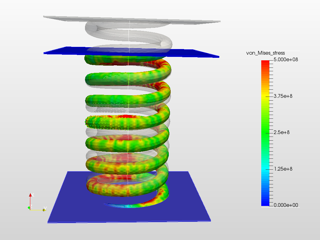
Is it actually possible to show stresses in a single direction only instead of Von Mises Stress?
Can you isolate a certain component/solid for which you only want to see results?
I’m a bit surprised I see a constant stress for two plates, while I would expect to see some stress variation along the plates (high peak stress at the contact areas with the spring and low stresses at the ends)? Is this due to scaling of the values or due to the coarse mesh I’ve used?
 I’ve already updated some items, such as Tolerance of the convergence criteria (0.001 --> 0.01), Maximum Newton Iterations (15 --> 30), Reactualisation every nth increment (kept equal to 1) and Timestep definition (kept equal to manual). But unfortunately I still get an error after a while (Newton Convergevence could not be reached).
 Unfortunately, I have some issues now with convergence of the solution. I’ve moved the questions about this to another topic “Master and Slaves” as I believe it better fits in this discussion?
 Since it is directly related to the Sideways Moving Spring topic. Can you move your posts here again?