Hey @jvarkevisser!
Glad that it worked for you! 
Yes it is possible! for now I have deleted the cauchy stress solution field. You can again create a new by going in to Solution fields under Result Control and add a new solution field. You have to create a new run and finish it to get the desired solution field results.
Yes you can do that but so far not on the online post-processor. Local Paraview can be used to do so. Please follow this post for post-processing. All you need to do is to apply the Extract Block filter and only extract the volume you need.
It shouldn’t be a surprising point! it’s due to the fact that both of our upper and lower bodies are completely rigid. For the lower one whole volume is constrained in all directions, whereas for the upper one whole volume is constrained in 2 directions. If you want to make them non-rigid, you have to refine a bit the internal faces of the two plates and then only constrain the upper faces with the same boundary conditions. You will then be able to see the stresses in plates also. But also keep in mind that doing so will increase the computation overhead and may not converge as easily as it did before.
Hope this helps. If you have any question/s, feel free to ask.
Best,
Ahmed
Hi Ahmed!
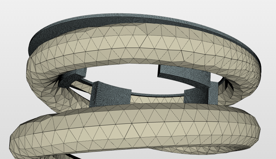
In the meantime I’m trying t further refine my model with some more detailed end plates:
As you proposed above I’ve further refined the mesh of the end plates and set the load & boundary conditions on the faces of the complete volumes. For the top face (i.e. face 73) this means I have to apply both the fixed boundary condition (including sideways movement) and the load. But when I try to do this I get the following error:
Warning: Displacement and force boundary conditions on the following entities.
faceGroupOnGeoFaces_73
I’m not sure what this error implies? Am I not allowed to define the conditions this way?
Cheers!
Hey @jvarkevisser!
This is not the error. It’s just a warning saying that you have applied load and constraint boundary condition to the same face. This will not effect your simulation run. Therefore, just go ahead and run your simulation.
It will be great if you can give a link of your project but not the public project link. Because most of the time user don’t want to import your project but rather just want to view it. In this case you can also edit your previous comment and add the normal project link rather then public project link. Hope you understand 
Best,
Ahmed
I had a look in to your case, there are two things you can do:
-
The top and bottom plates are too refined, just coarse them a bit. Moreover, spring is very coarse which is not good. I think you accidentally gave the spring to the coarse mesh refinement zone.
-
You need to define your contact something like this:
Where, master will be plate surfaces and slave will be spring surfaces.
I think the error occurred in your simulation is due to rigid body movement of spring along y-axis. Either increase the spring stiffness or give more area to elastic support.
Hope this helps. If you have any question/s, feel free to ask.
Best,
Ahmed
1 Like
Hi Ahmed!
Thanks again for the Help! In the meantime I’ve updated the mesh a bit and also further increased the stiffness of the elastic support (500000N/m). But unfortunately, still convergente issues,. Even when I leave out the sideways movement and reduce the applied load for the moment. Furthermore, the master-slave assignments should be Fine I think?
I Have the feeling that current model shouldn’t be harder to solve than the previous one with the simple End plates and slightly less Extended Spring ends?
Hi Ahmed!
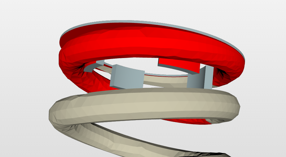
I’ve done some additional analyses with the spring model:
I noticed that when I temporarily select a bonded contact between the spring and top plate (i.e. connection 2) the simulation will eventually converge. So, at this point I think the top plate is causing the convergence problem (as it is constrained in x- and y-direction and unconstrained in z-direction).
In the meantime I’ve done an additional run using an additional elastic support for the top plate (connected to the top face, stiffness 500000N/m), but it’s again not converging anymore… Any ideas how to go on with this?
Cheers
Hey @jvarkevisser!
I will have a look at your project and come back to you as soon as I have some results.
Best,
Ahmed
2 Likes
Hi Ahmed!
Bingo
After trying many things it suddently came to mind that maybe the final parts of the spring might cause the non-convergence issue (maybe they are too thin to be meshed properly for this non-linear simulation?). I’ve updated the spring (cut-off the final bits of the spring ends) after which I rerun the analysis and this time it converged!
Maybe it’s still possible to succesfully run a simulation with the original spring (with thin ends), but I think I have to further refine these ends. Do you think this reasoning makes sense?
Cheers
1 Like
Hey @jvarkevisser!
Glad that it worked!  Well in a meantime I was always trying to run your case. It seems like you were having the problem with your geometry. The created mesh had some orphan nodes which were not belonging to the mesh. I think in my case the application of elastic support was always on these nodes somehow. Whereas, you were probably lucky to run it without any problem.
So I exported the mesh, removed the orphan nodes but still remained with the multiple overlapping elements. Opening your geometry in one of our CAD tool reveals that one of your spring face was distorted. I think this was the problem. I created a new spring and imported it to check if it works. It did start working but the solution wasn’t stable that much.
On the other side, doing a static test simulation revealed that your plate is quite thin and your spring is having the same material as your plates, this makes the plates to bend if the pressure is applied over it. Either your spring needs to be softer or you can apply a displacement boundary condition on top surface to avoid this bending of the plate. In the real world case also I think these plates are connected to some system which don’t allow them to bend in any direction.
I will try to converge the solution an will return with some results.
Best,
Ahmed