Aerospace Workshop Session 3: Aerodynamics of an Aircraft - Part I Meshing
Recording
Aerospace Workshop feat. EUROAVIA (Session 3) ― Compressible Aerodynamics of an Aircraft
This project aims to perform the aerodynamics simulation of an Aircraft model at different flow velocities and 2 different setups. First case is with free domain boundaries and the second is close to the ground.
The figure below describes briefly the two cases:
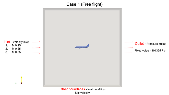
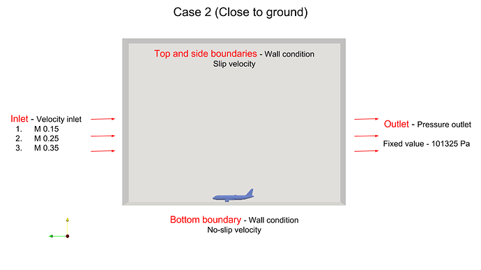
The table below gives the flow velocities for the different setups:
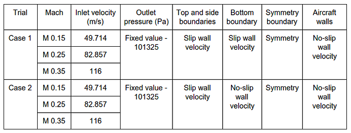
Note: For cases with M=0.35, Velocity Ramping is required via a file upload which is explained later in the simulation setup.
For these cases we will use the Hex-Dominant Parametric meshing operation which provides full functionality to mesh complex geometries. The Tutorial below will provide detailed steps on how to use each meshing feature to get a well resolved mesh.
Step-By-Step
Import the project by clicking the link below. ( Crtl + Click to open in a new tab )
Click to Import the Homework Project
Once the project is imported, the workbench is automatically opened. Then follow the steps below for setting up a compressible flow simulation.
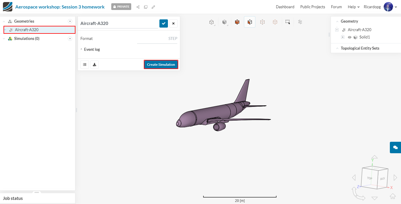
Select the newly imported Geometry and click Create Simulation:
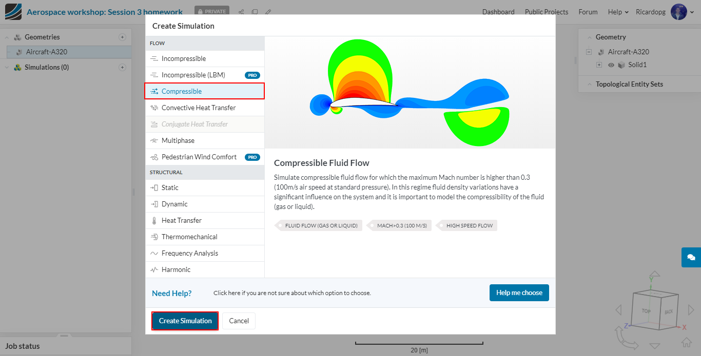
In the window that opens, please select Compressible and then give another click on Create Simulation:
The simulation tree now can be found in the left-hand side of your screen. Notice how some entries are marked in red. These have some inputs missing and need to be filled out. The ones marked in green have the necessary inputs to run the simulation (but you can always change their inputs if it is necessary).
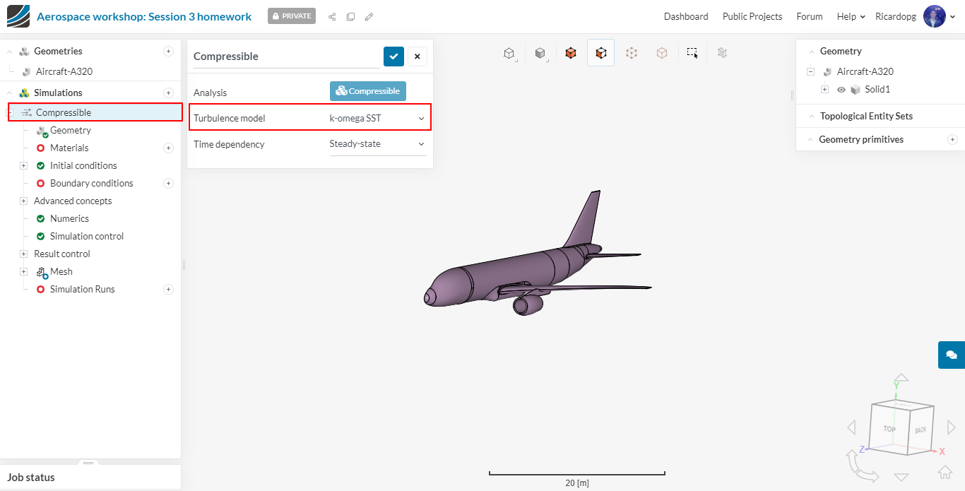
In the simulation tree, click on Compressible and make sure the Turbulence model is set to k-omega SST and Time-dependency to Steady-state.
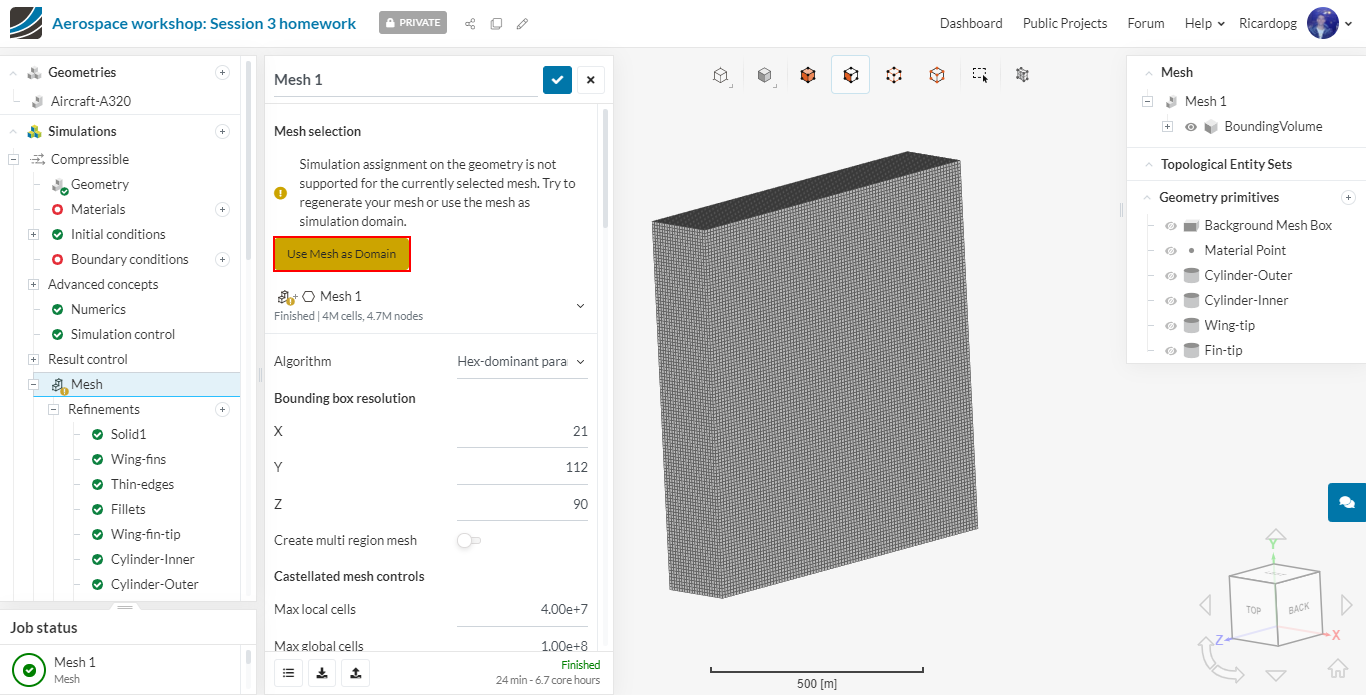
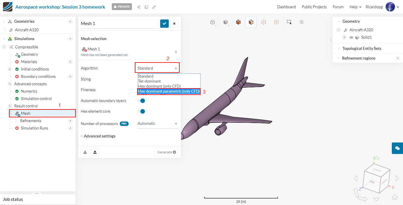
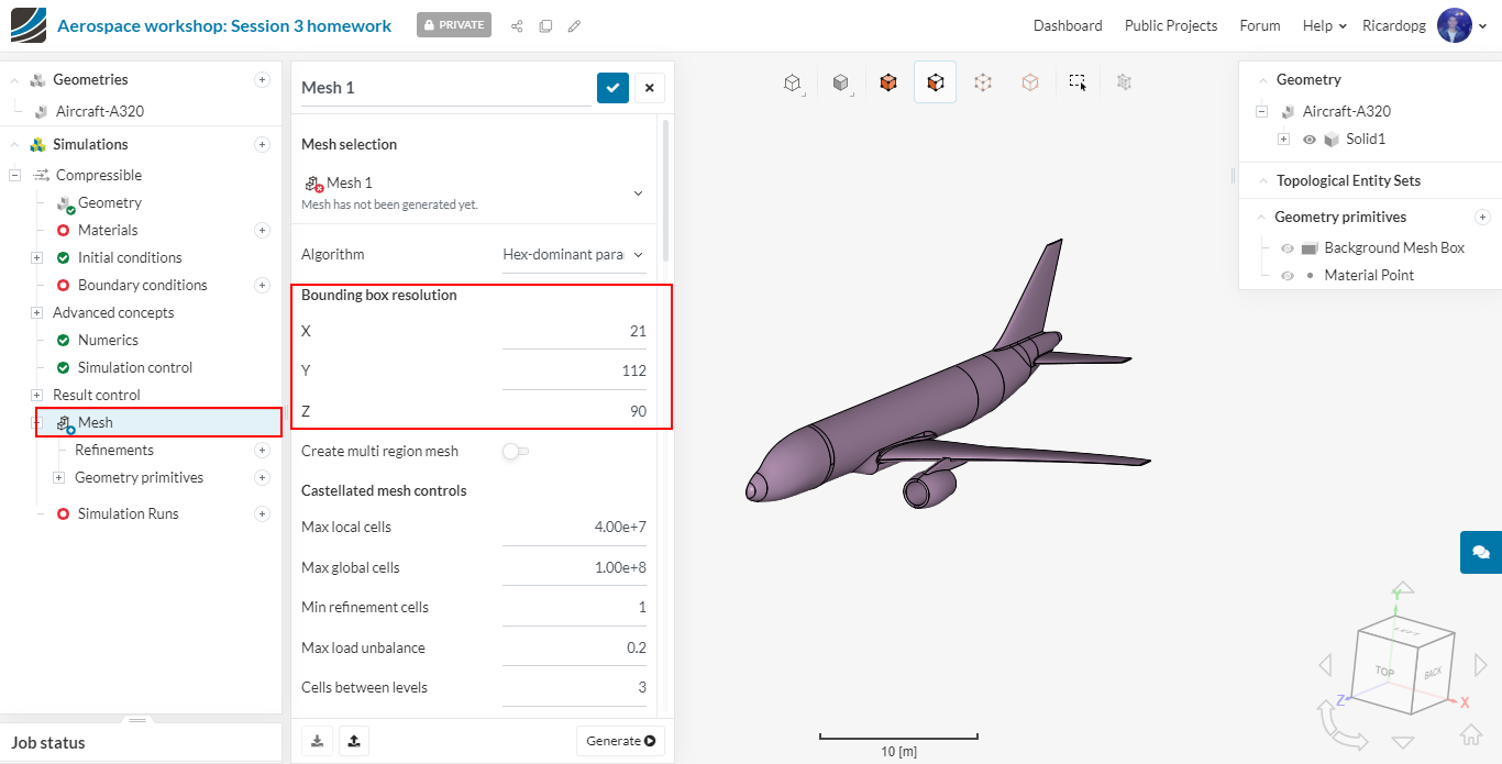
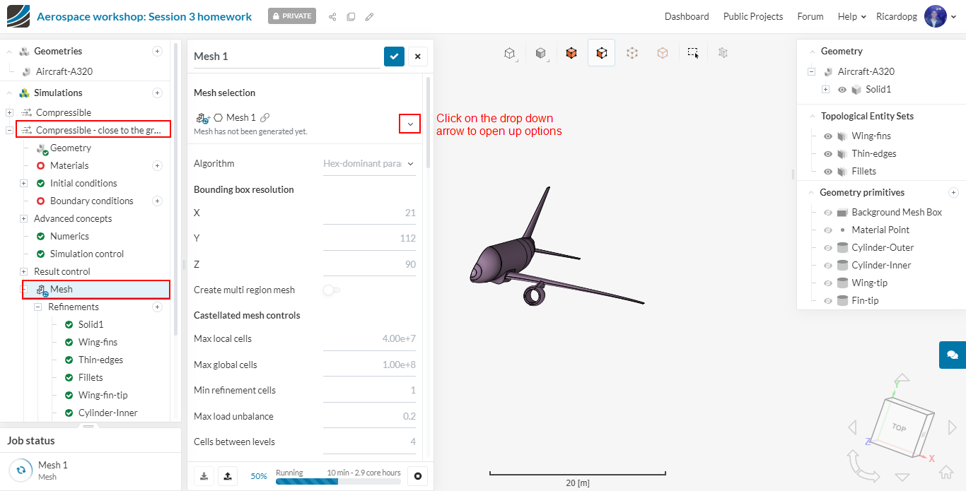
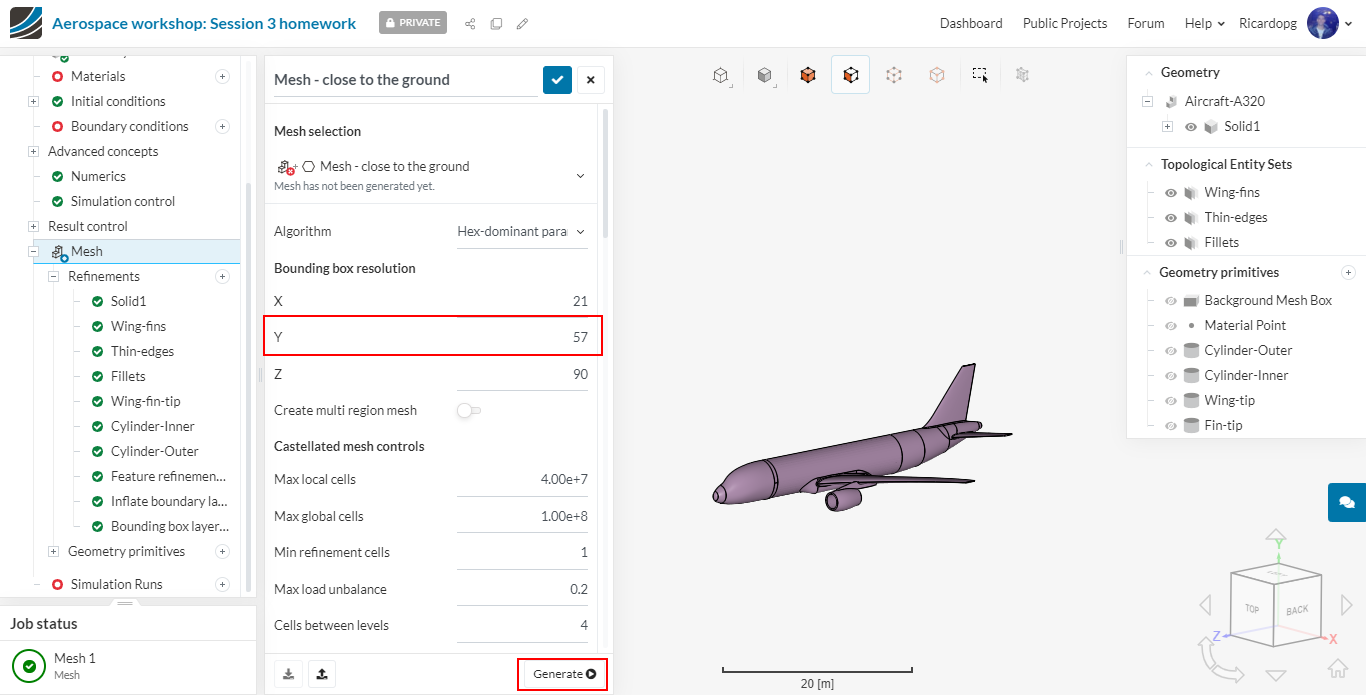
The rest of the setup will be done in the next session. We will now focus on meshing the geometry. Please click on Mesh in the simulation tree. Change the Algorithm to Hex-dominant parametric (only CFD).
Adjust the Bounding box resolution to:
Number of cells in X-direction: 21
Number of cells in Y-direction: 112
Number of cells in Z-direction: 90
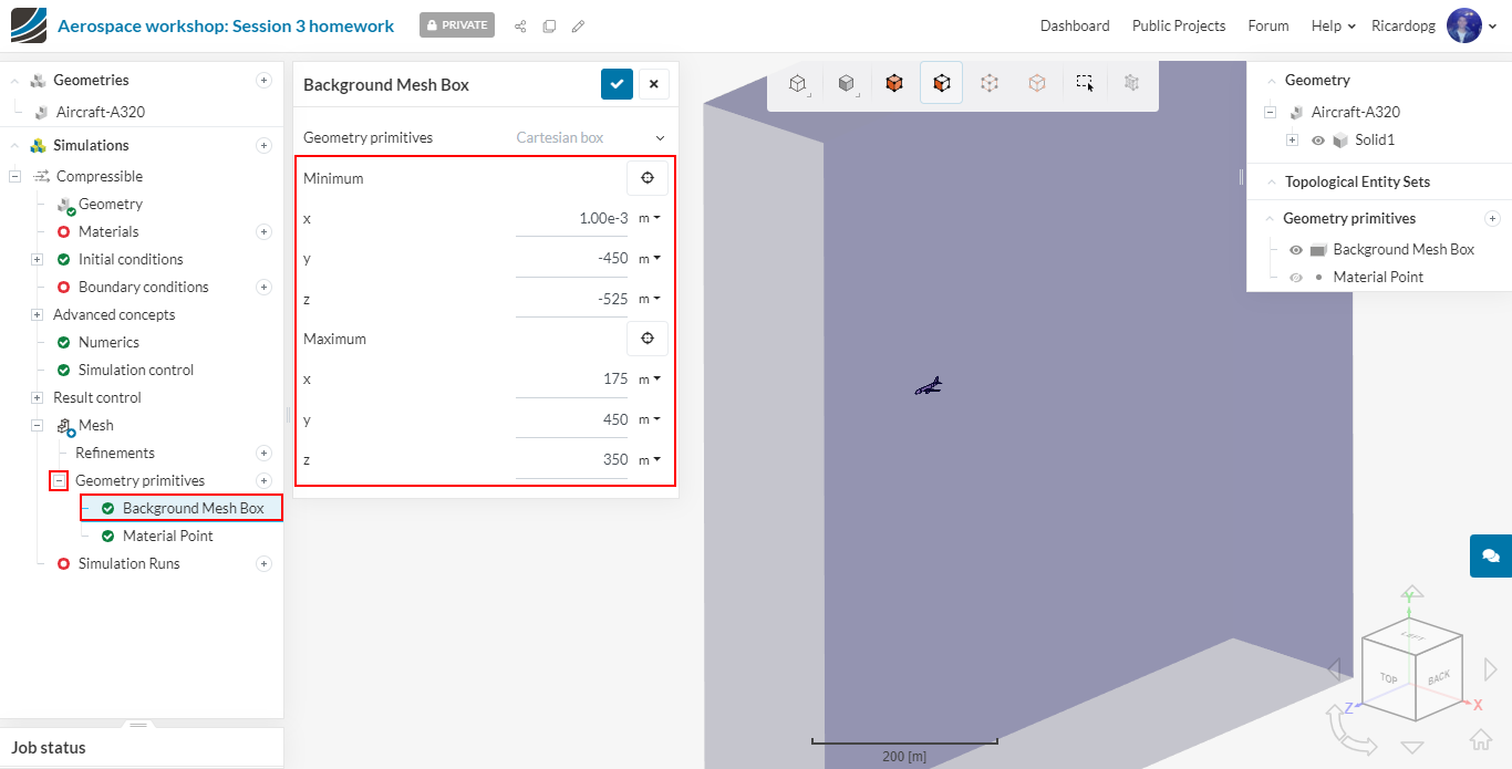
After saving, the tree is extend with a Geometry primitives entry. Expanding this entry, you will find two primitives that are automatically created: Background Mesh Box and Material Point. In Background Mesh Box, change the coordinates to the values specified below:
Min X= 0.001
Min Y= -450
Min Z= -525
Max X= 175
Max Y= 450
max Z= 350
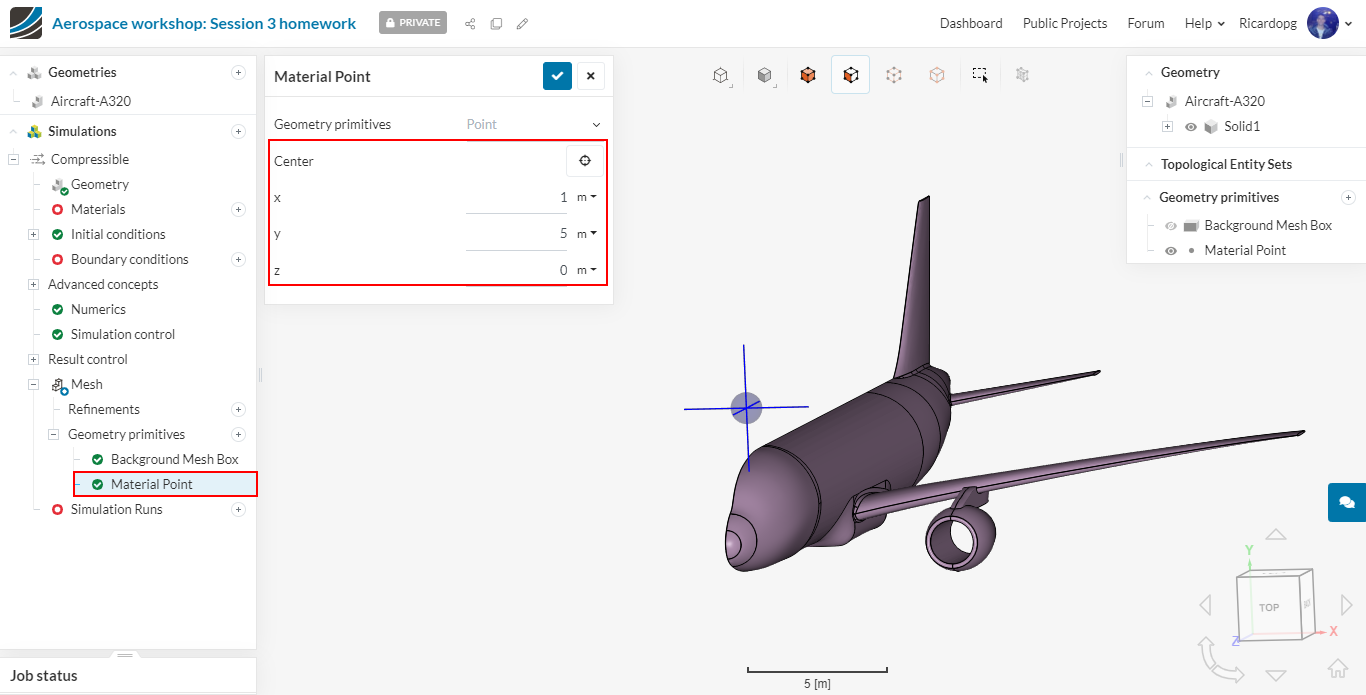
Now we can place the Material Point anywhere in the flow region. The region specified by the material point is the one that will be meshed. The following coordinates work:
Center X = 1
Center Y = 5
Center Z = 0
Further primitives
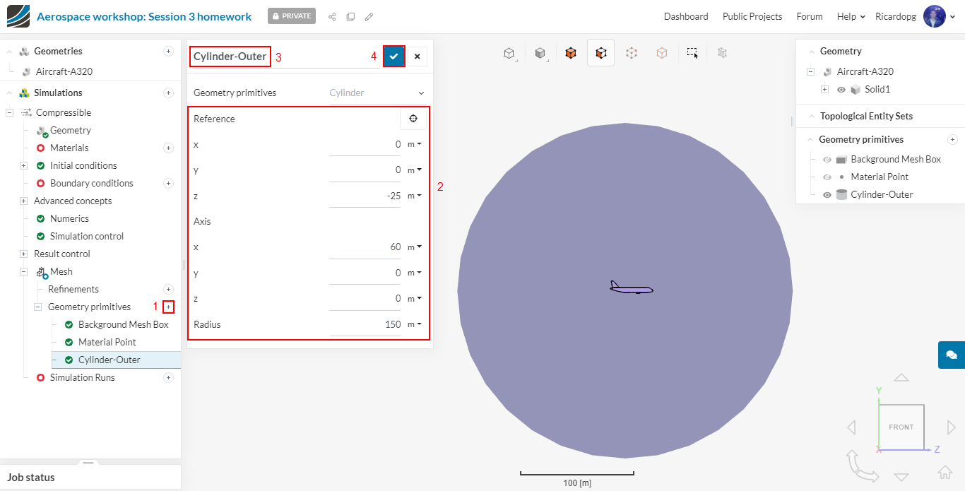
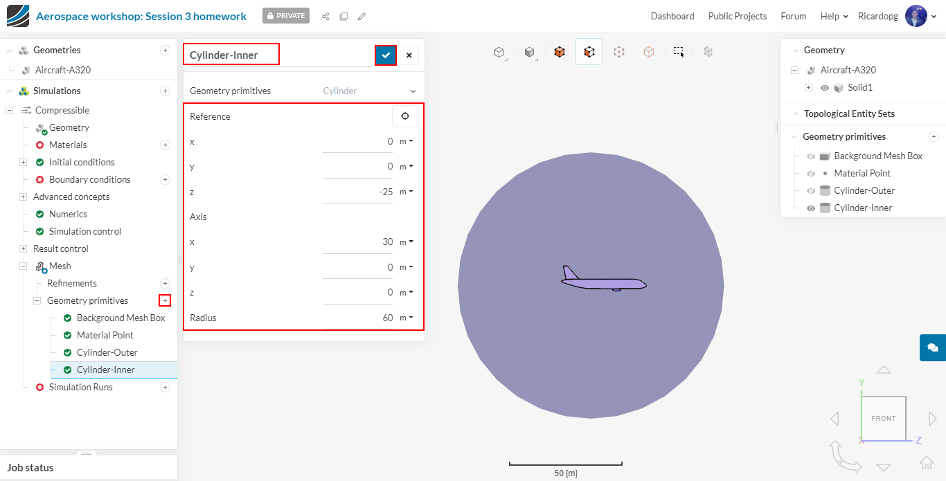
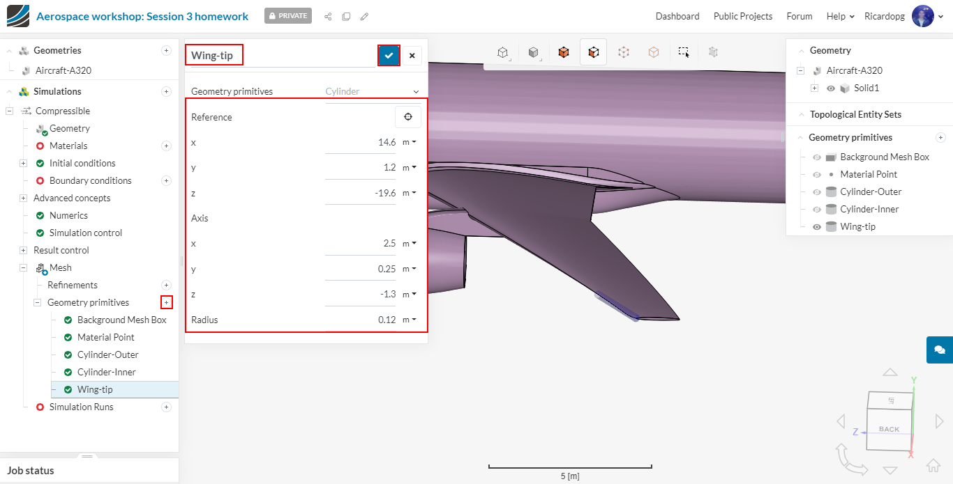
- We will create 4 entities that will be used for mesh region refinements later in the meshing setup.
- To create a New entity, click on the + icon next to Geometry Primitives and then select the type of primitive. In our case, all 4 will be Cylinders.
The table details the parameters for the 4 cylinder entities that are shown in the figures below.
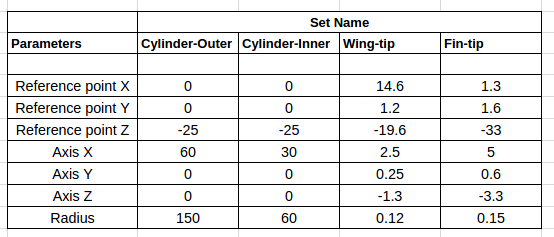
Creating the Cylinder-Outer primitive:
Creating the Cylinder-Inner primitive:
Creating the Wing-tip primitive:
Creating the Fin-tip primitive:

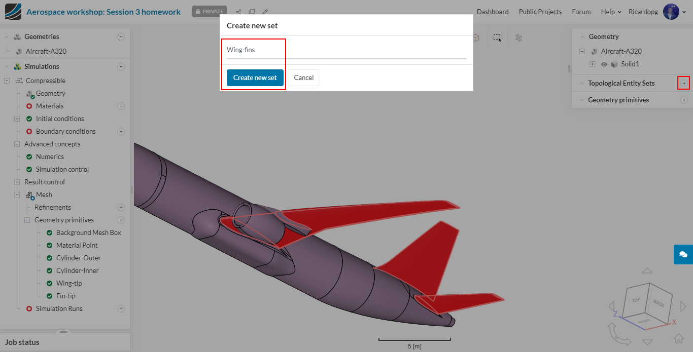
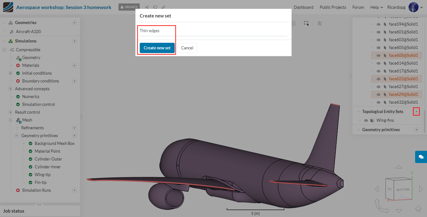
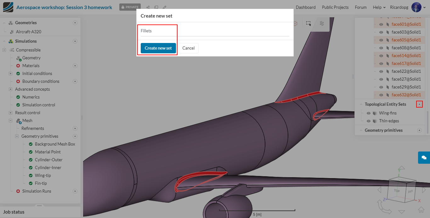
Let’s now create some Topological Entity Sets which will be used to create mesh refinements. To create a new topological entity sets, the following steps have to be followed:
- Select the face or faces that will be part of the newly created set;
- On the right-hand side of the screen, next to Topological Entity Sets , click on the + icon;
- Name the new entity set as you deem suitable.
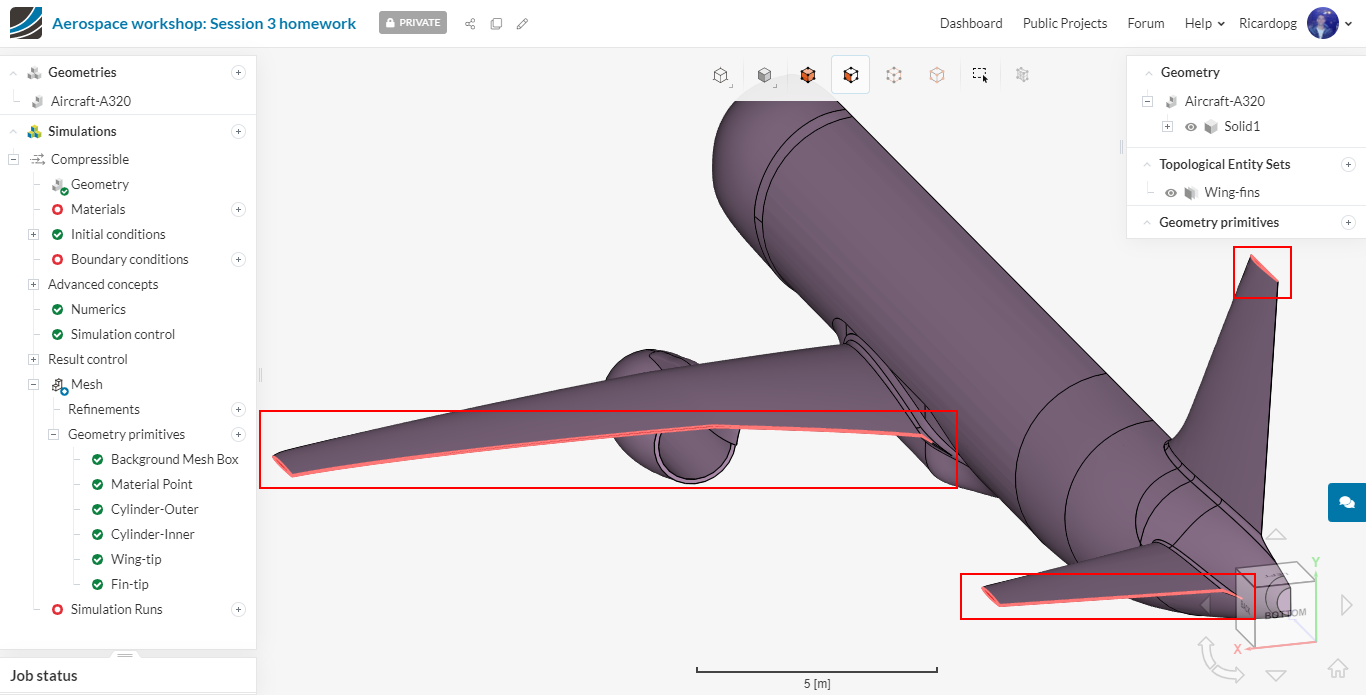
The first set will be named Wing-fins. It consists of the bigger parts (i.e. not edges) of the wings:
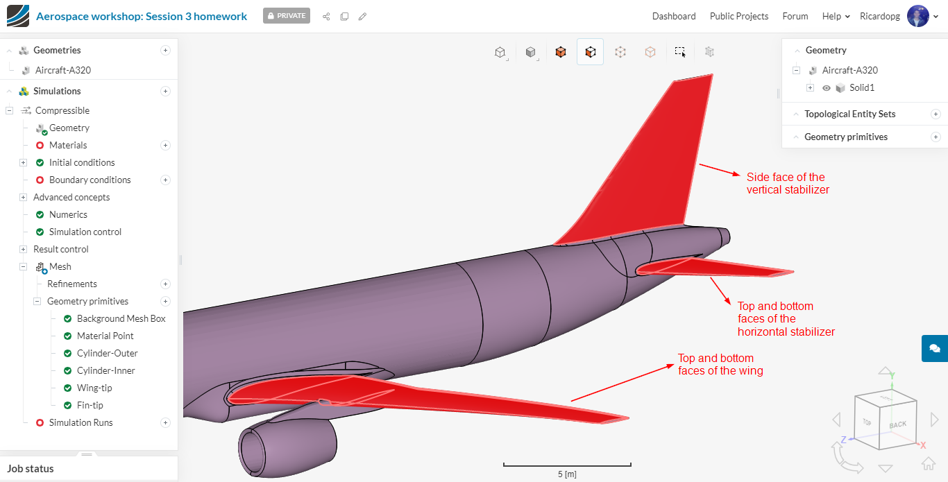
5 faces in total will be selected.
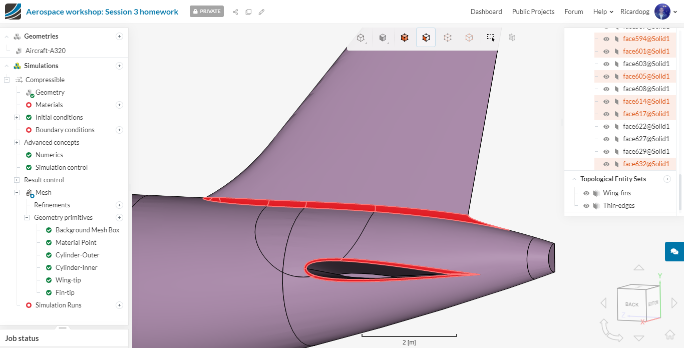
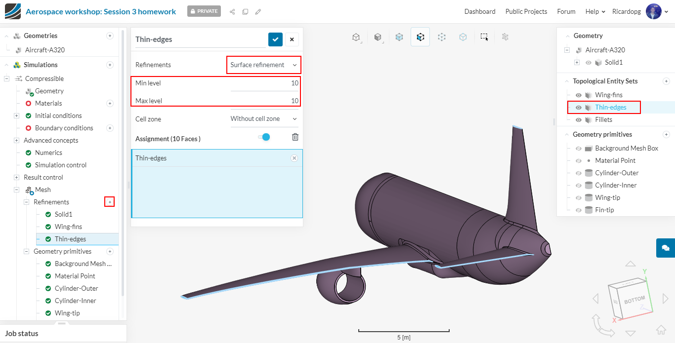
Now let’s create a Thin-edges entity set. The faces we are looking for are the small edges on the tip and on the trailing edge of the wings:
10 faces in total will be selected. 4 on the wing, 5 on the horizontal stabilizer and 1 on the vertical stabilizer.
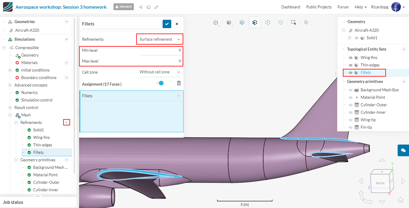
Last set will be named Fillets. For this set, we will assign all the fillet surfaces connecting the wing and stabilizers to the fuselage:
17 faces in total were selected for this set: 7 on the wing, 4 on the horizontal stabilizer and 6 on the vertical stabilizer.
Mesh Refinements
We will now add the necessary mesh refinements for the previously created topological entity sets and the geometry primitives.
Click on the + icon next to Mesh Refinements and choose the desired type of refinement.
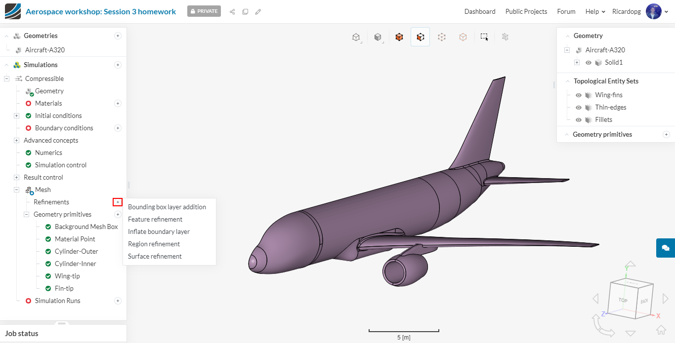
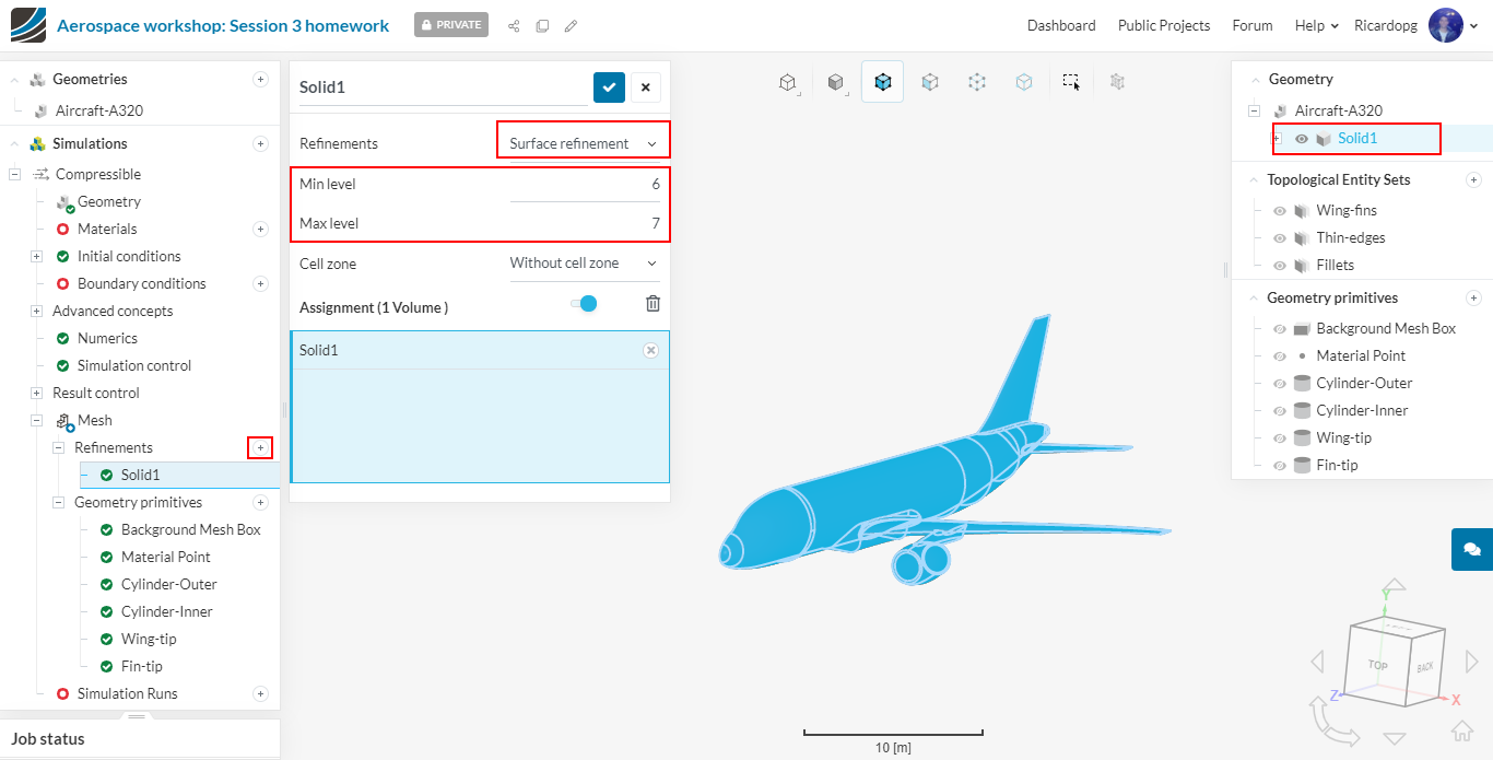
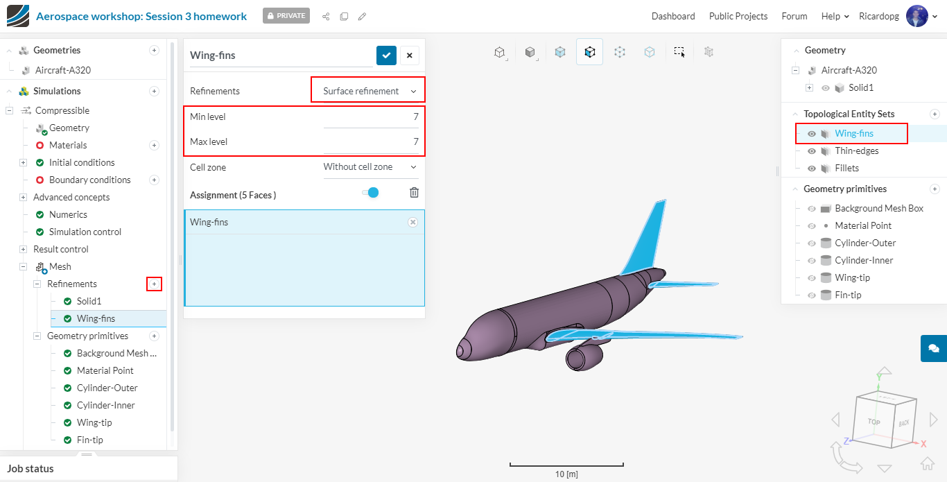
Surface refinements:
Solid1: this refinement will be used to refine all surfaces of the airplane:
Wing-fins: this refinement will be used to further refine the Wing-fins topological entity set:
Thin-edges: this refinement will be used to further refine the Thin-edges topological entity set:
Fillets: this refinement will be used to further refine the Fillets topological entity set:
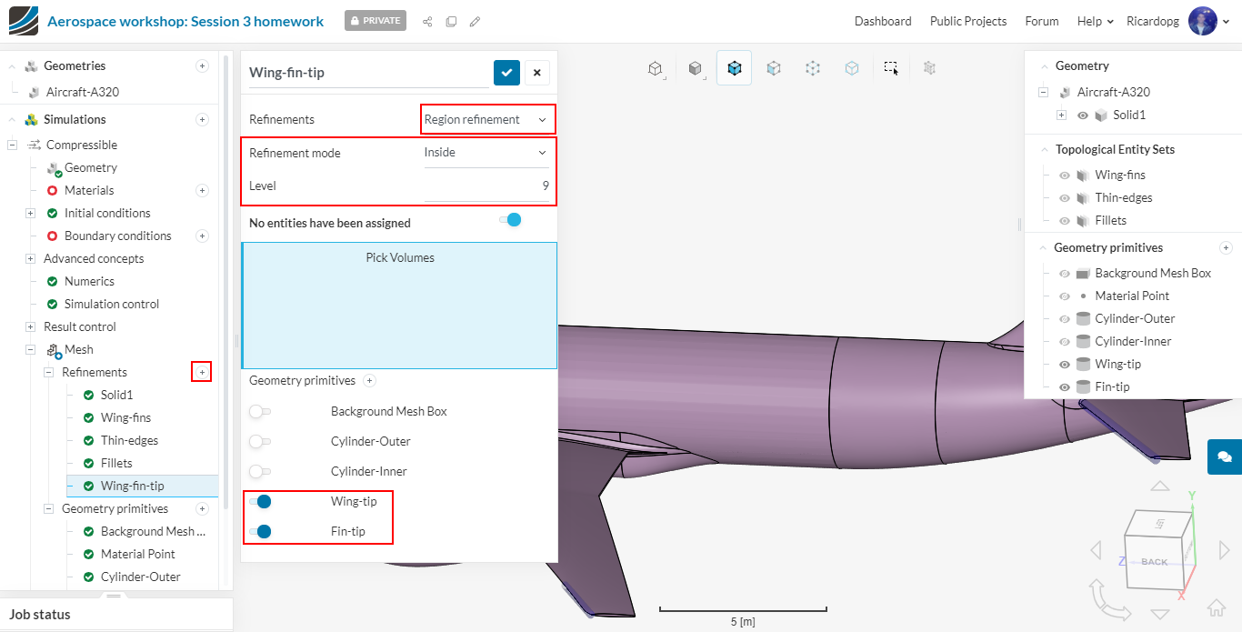
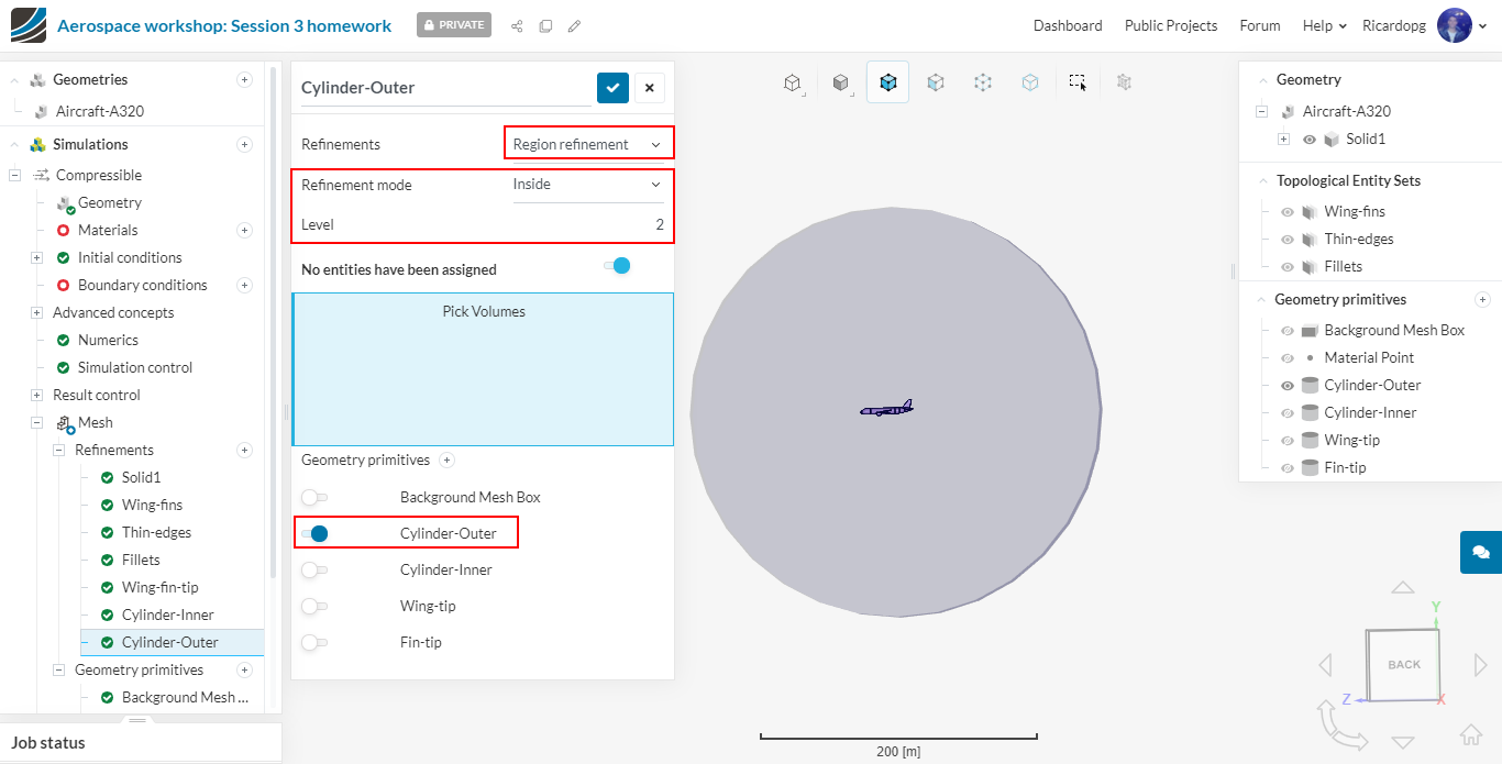
Region refinements
These refinements will refine the volume mesh. We will create 3 region refinements and assign them the previously created geometry primitives.
Please set up the Wing-fin-tip region refinement as shown below:
Now please set up and Cylinder-Inner region refinement as shown below:

Lastly, the Cylinder-Outer region refinement will be created:
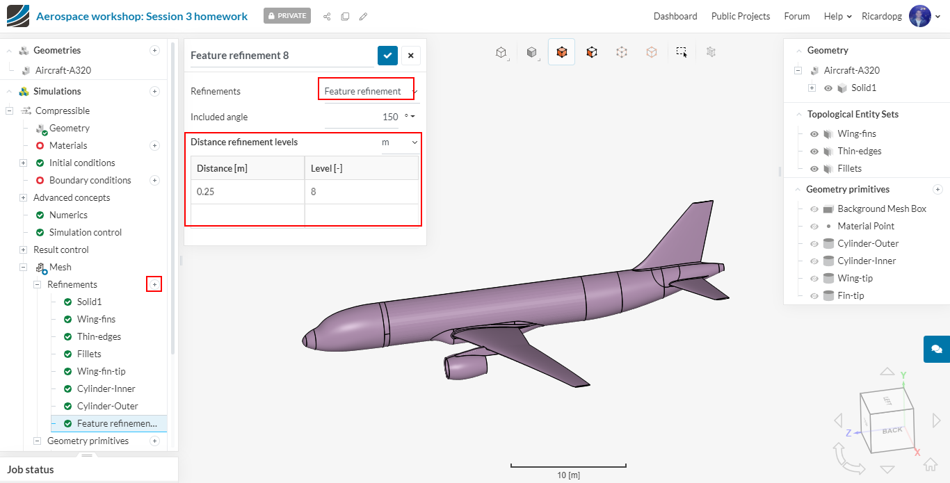
Feature refinement
The feature refinement will refine near edges. This is important to capture sharp corners.
So please add a Mesh Refinement and choose Feature Refinement. Give a Distance of 0.25 m and a Level of 8.
Inflate boundary layer
The layer refinement is important to capture the boundary layer near the wall. This will create layer cells following the surface curvature near the walls.
Please add a boundary layer refinement to all of the airplane faces with the following settings:
- Layers: 8
- Expansion ratio: 1.45
- Min thickness: 0.00001
- Final layer thickness: 0.3
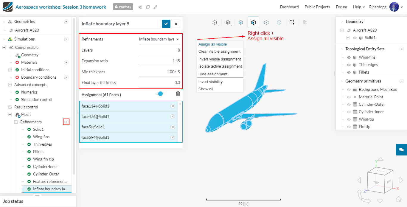
The thickness of the first layer is of particular interest. Consider reading this post on yplus if you haven’t already.
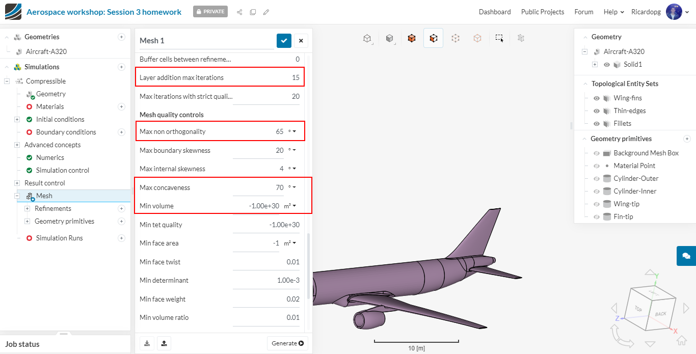
Lastly, we will change a few parameters in the advanced settings. This will help to get a good quality mesh for a complex geometry. In the simulation tree, click on Mesh and scroll down through the settings panel. The parameters that will be changed are highlighted in the pictures below.
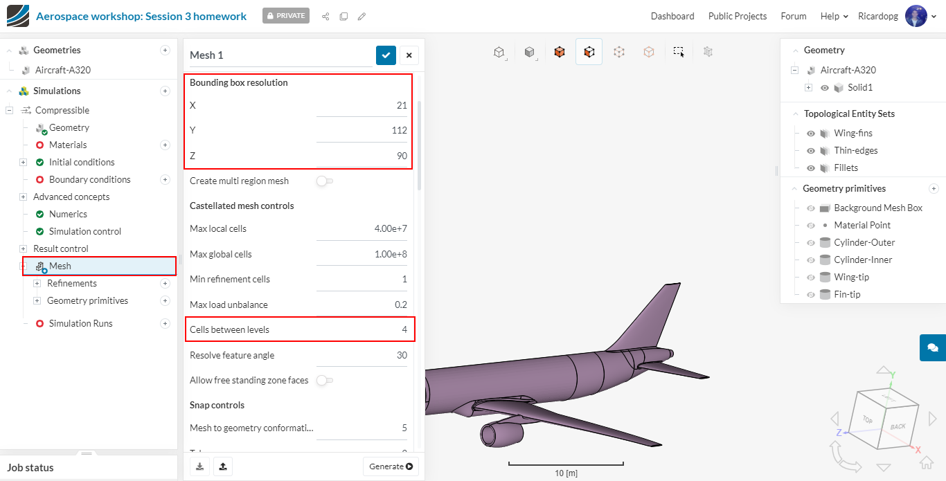
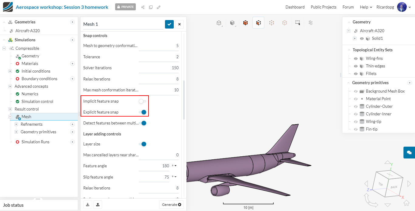
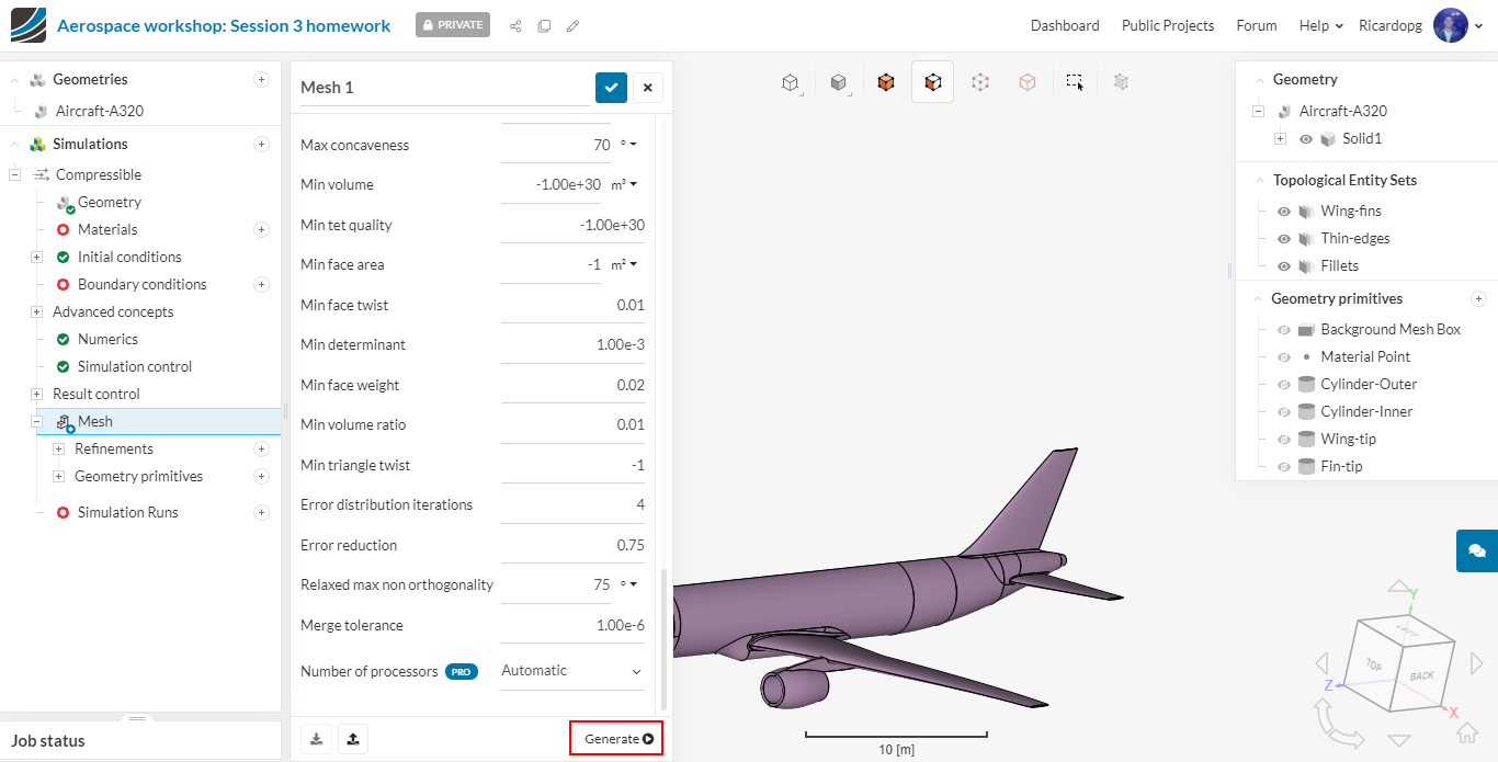
After you’re done adjusting the settings, we are ready to generate our mesh! So please click on the Generate button. You don’t have to worry with the number of processors being used. SimScale automatically determines the optimal number depending on the job size.
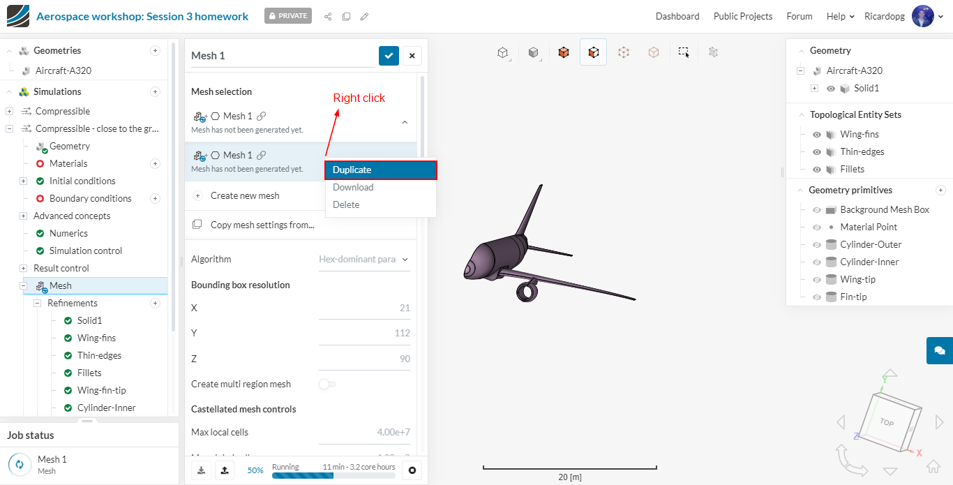
Mesh 2 - close to the ground
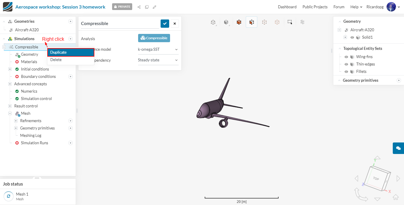
For simplicity and to keep our workbench organized, we will duplicate the first Compressible simulation by right clicking and clicking on Duplicate:
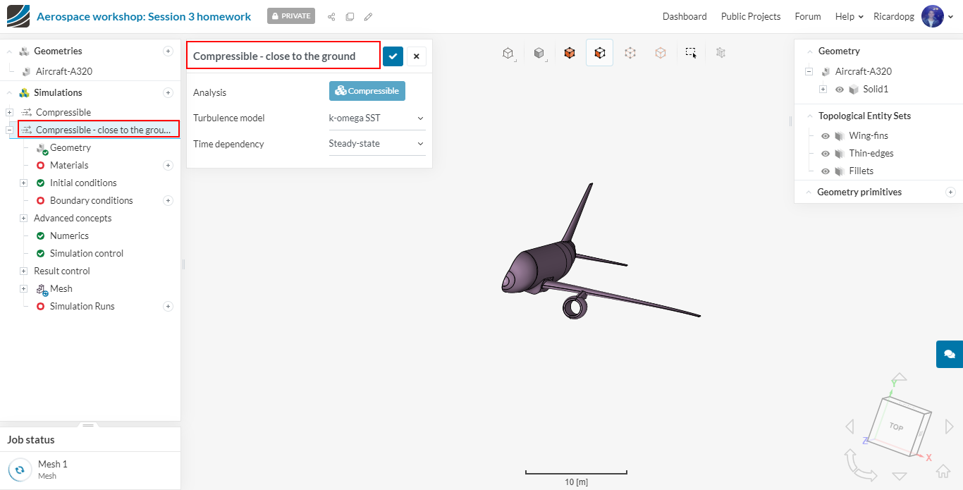
You can rename the second Compressible simulation to make it easier to distinguish between them.
Now let’s duplicate the first mesh that we have already set up. Proceed to Mesh in the simulation tree. Then please follow the steps below:
You can give the new mesh an appropriate name to make it easier to identify. This mesh, right now has the exact same settings as the one we previously created.

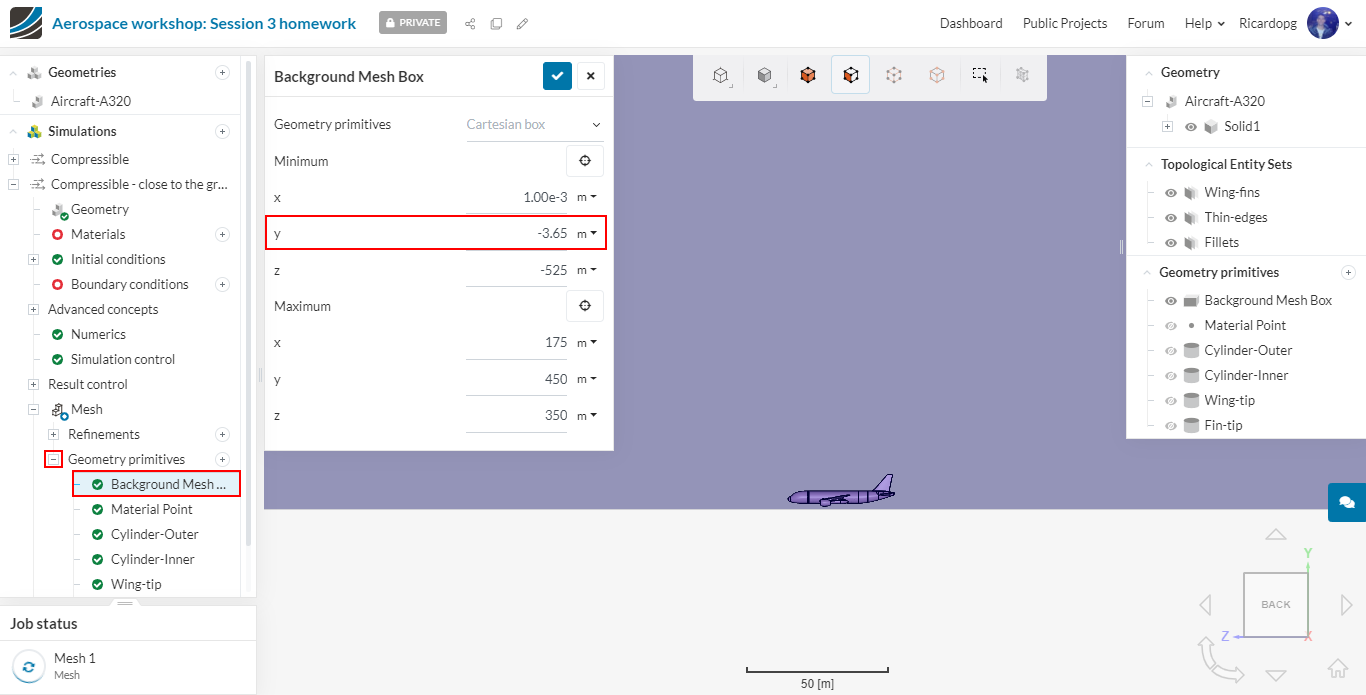
We will need to adjust some parameters of the duplicated mesh, namely the Background Mesh Box dimensions, the Bounding box resolution and also use one extra refinement.
Background Mesh Box: please navigate to background mesh box in the simulation tree. Change the Min Y input to -3.65 meters:
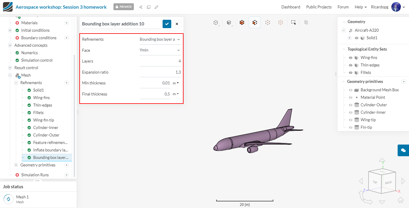
Let’s now make a Bounding box layer addition refinement:
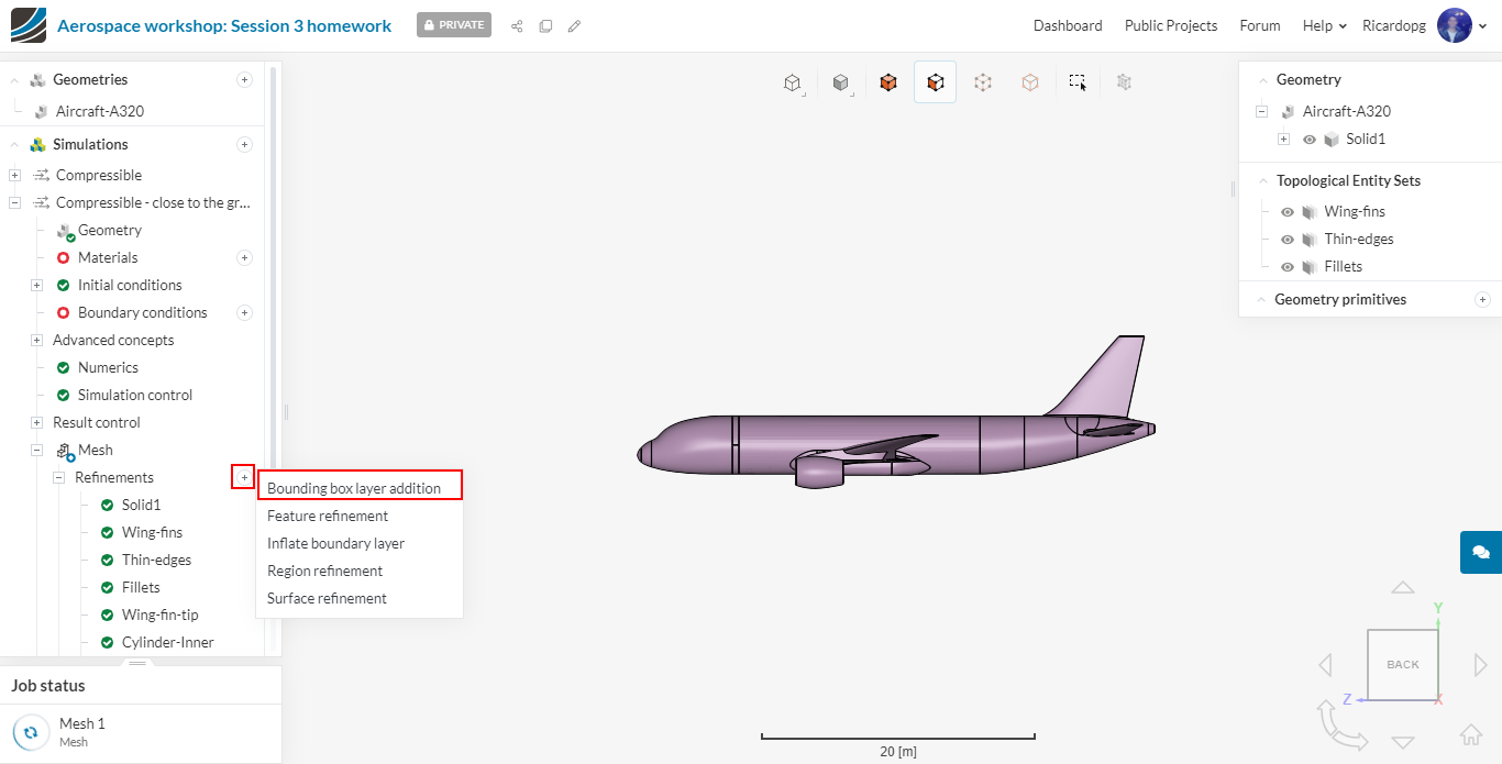
In the refinement configuration, please set
- Face to Ymin;
- Layers to 4;
- Expansion ratio to 1.3;
- Final thickness to 0.5;
- Min thickness to 0.01.
As the domain is now shorter in the Y-direction, we will adjust the Bounding box resolution by changing the number of cells in Y direction to 57. After this, we can Generate our second mesh aswell. Keep in mind that you can generate both meshes at the same time - SimScale allows multiple jobs in parallel.
When the meshes are ready, make sure to click on Use Mesh as Domain. This lets the software know that your mesh will be your flow region.