Session 1: Air-conditioning simulation of an office space

Air Conditioning and Ventilation Webinar

Air-conditioning simulation of an office space

Import the project by clicking the link below.

Project Link: https://www.simscale.com/workbench?publiclink=16a0754d-f8b0-464e-83b4-9159996a9cf9

Once the project is imported, the workbench is automatically opened. Then follow the steps below for setting up a convective heat transfer simulation.

Step-by-Step

Meshing

  • In the ‘Mesh Creator’ tab, click on the geometry ‘Office’
  • Then, click on ‘Mesh geometry’ button in the options panel.

  • Select the mesh type to be Hex-dominant automatic for internal flow (only CFD), select fineness 3 (Moderate), as shown in the image below.

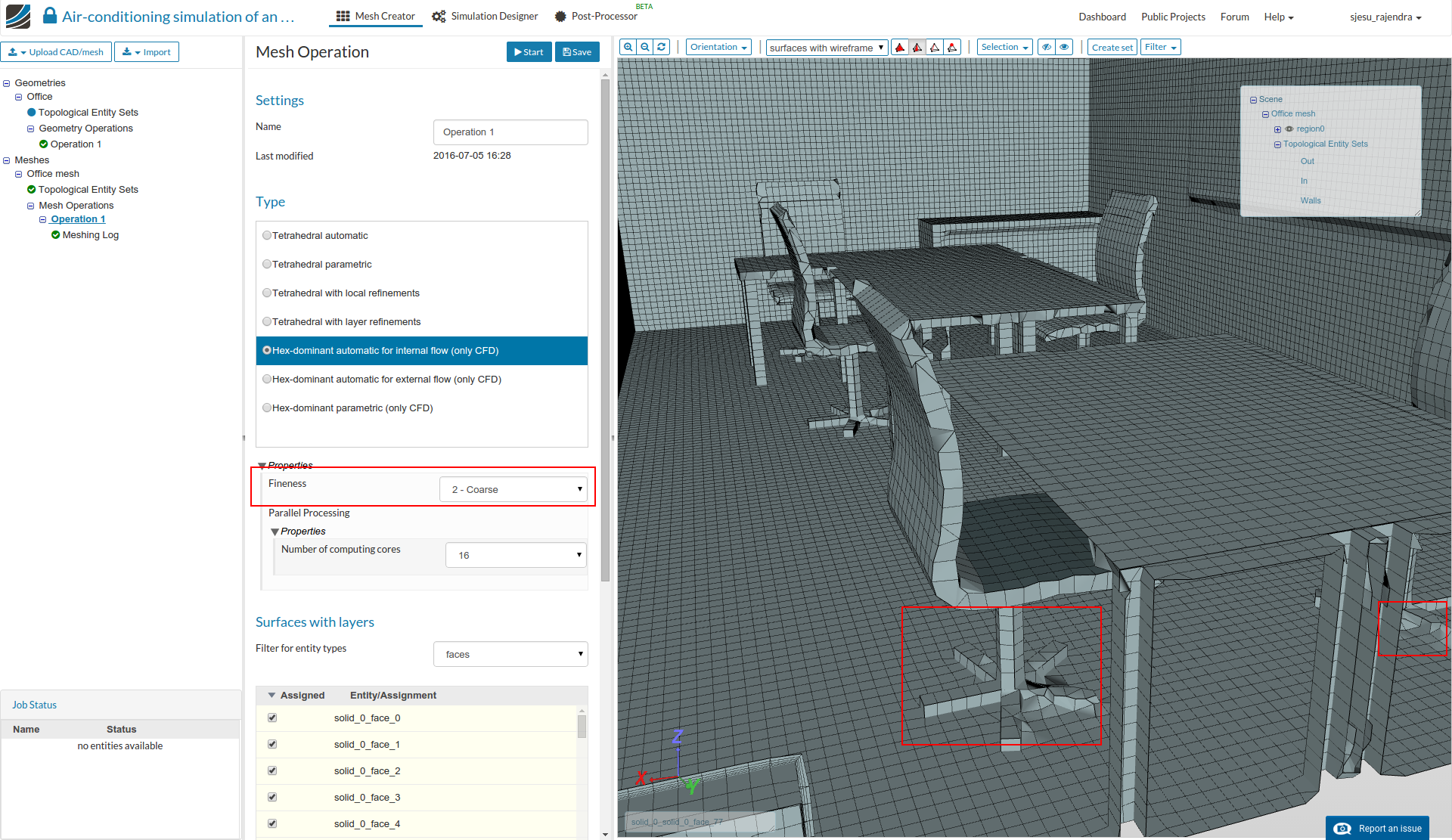
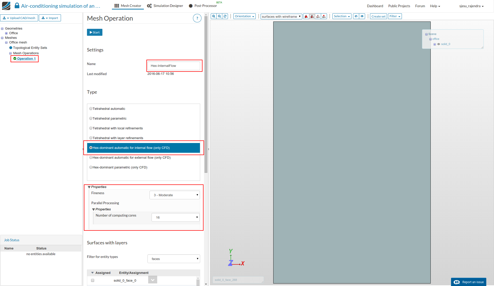
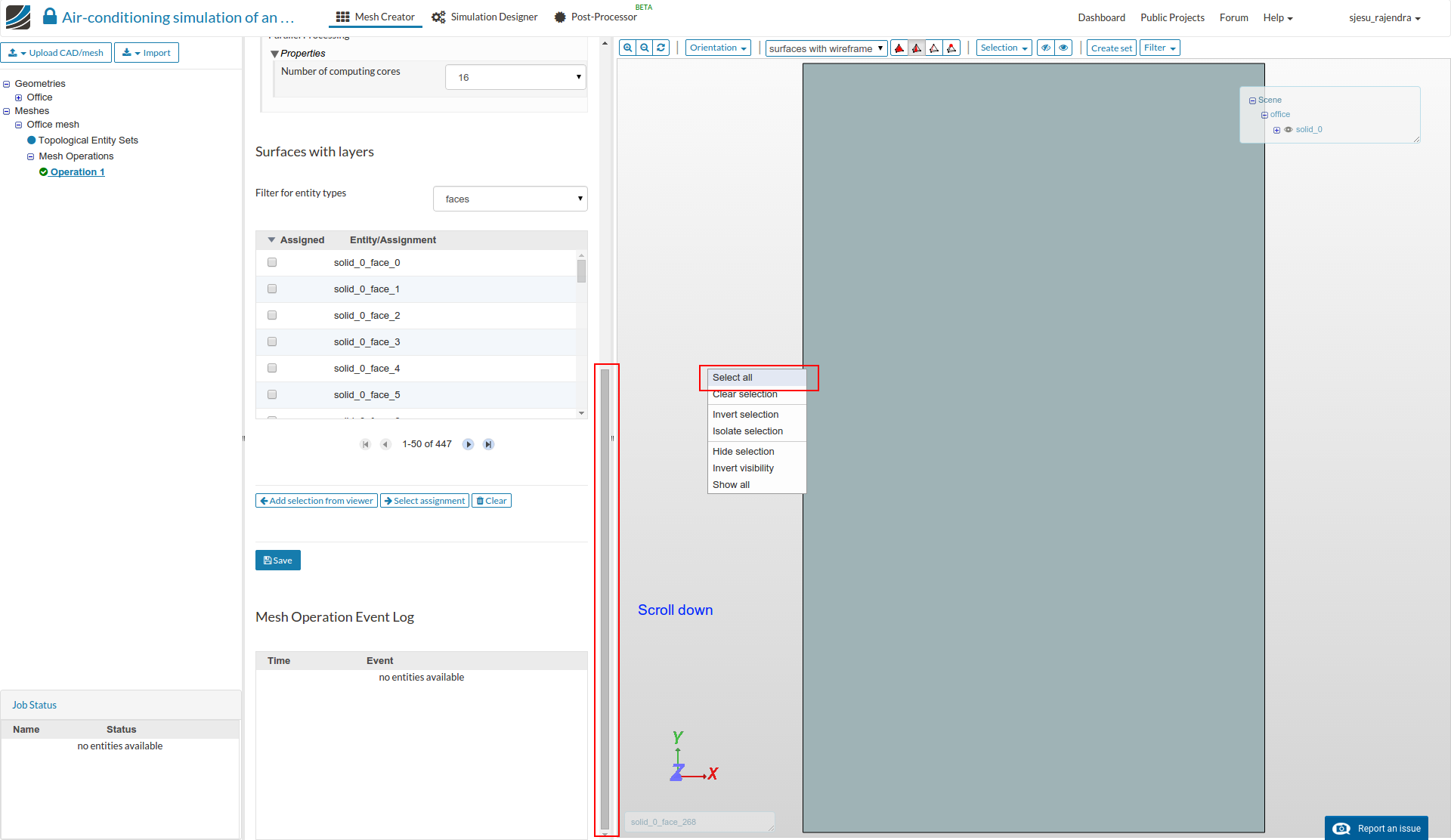
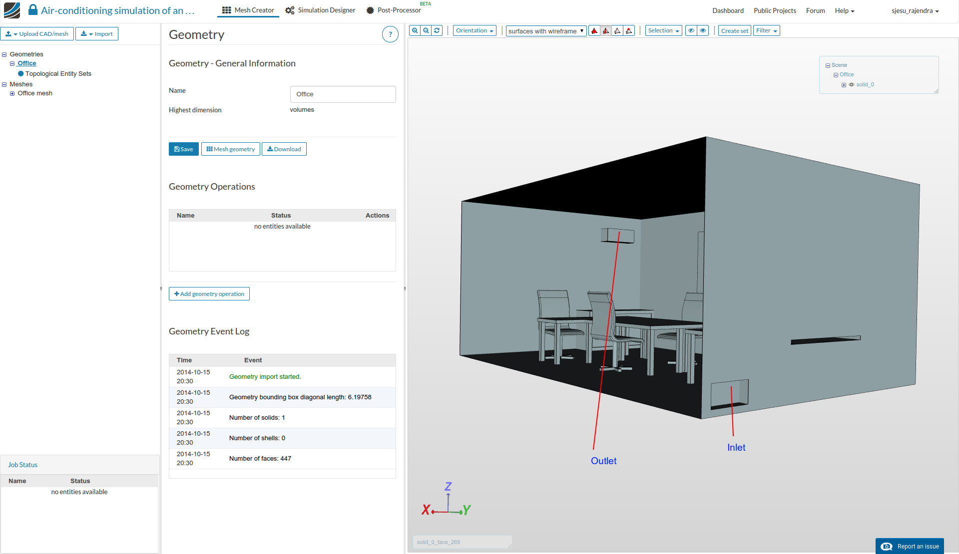
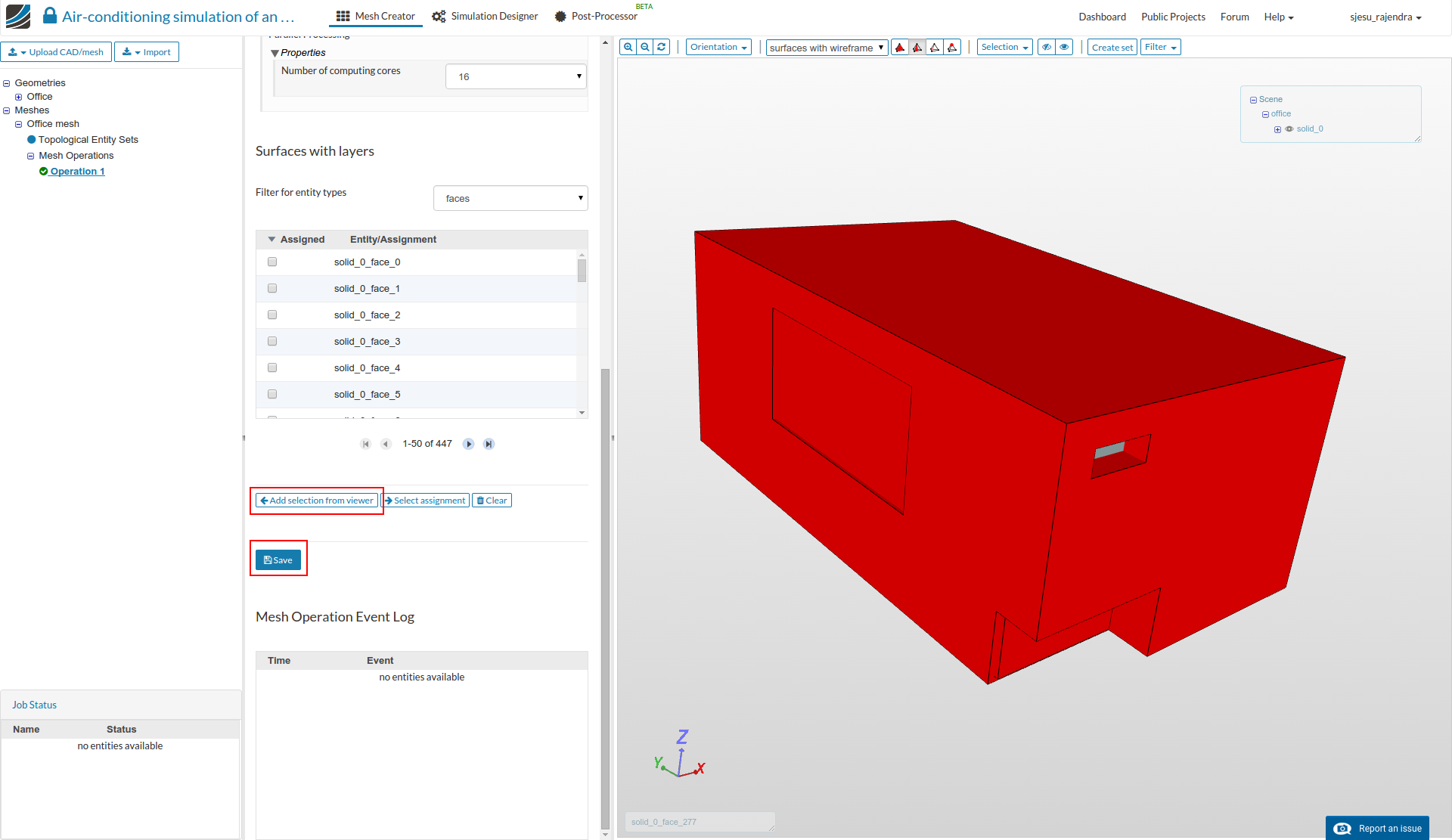
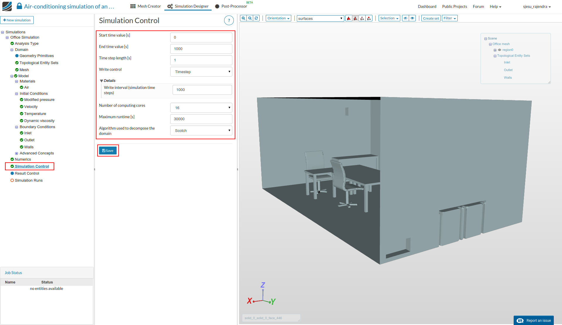
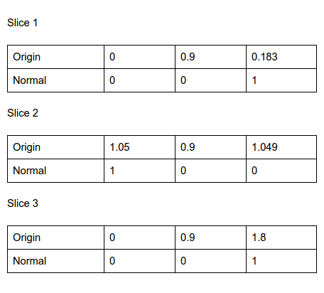
  • Layer addition is important to capture the flow phenomenon near the boundaries. Hence layers should be added to all the surfaces except the inlet and outlet. This can be done by selecting all surfaces and then deselecting the inlet and outlet boundaries, as shown in the following 2 images.

  • Apply these surfaces by selecting Add selection from viewer option and then click the Save button.

  • Select the Start to begin the mesh operation.

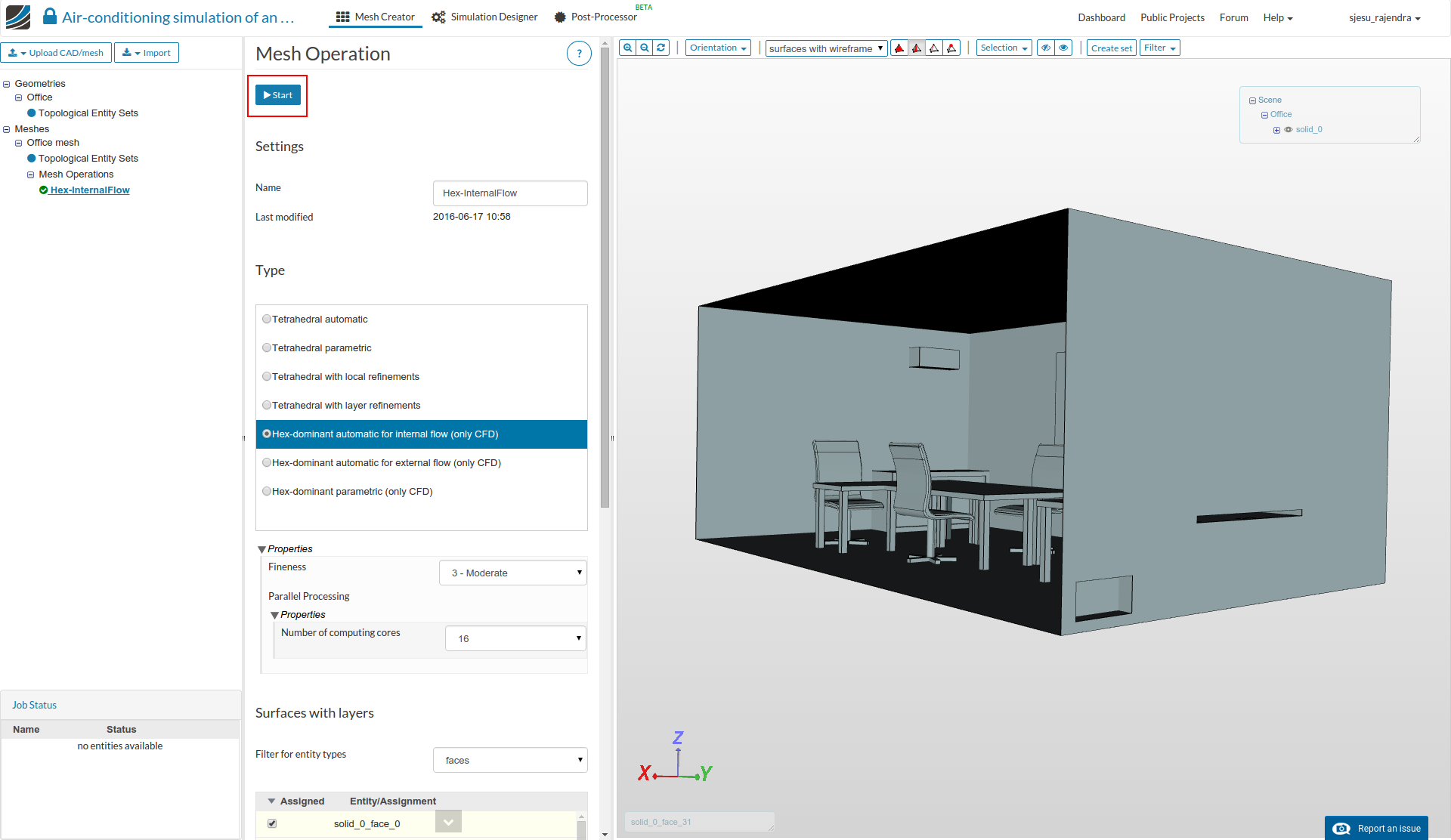
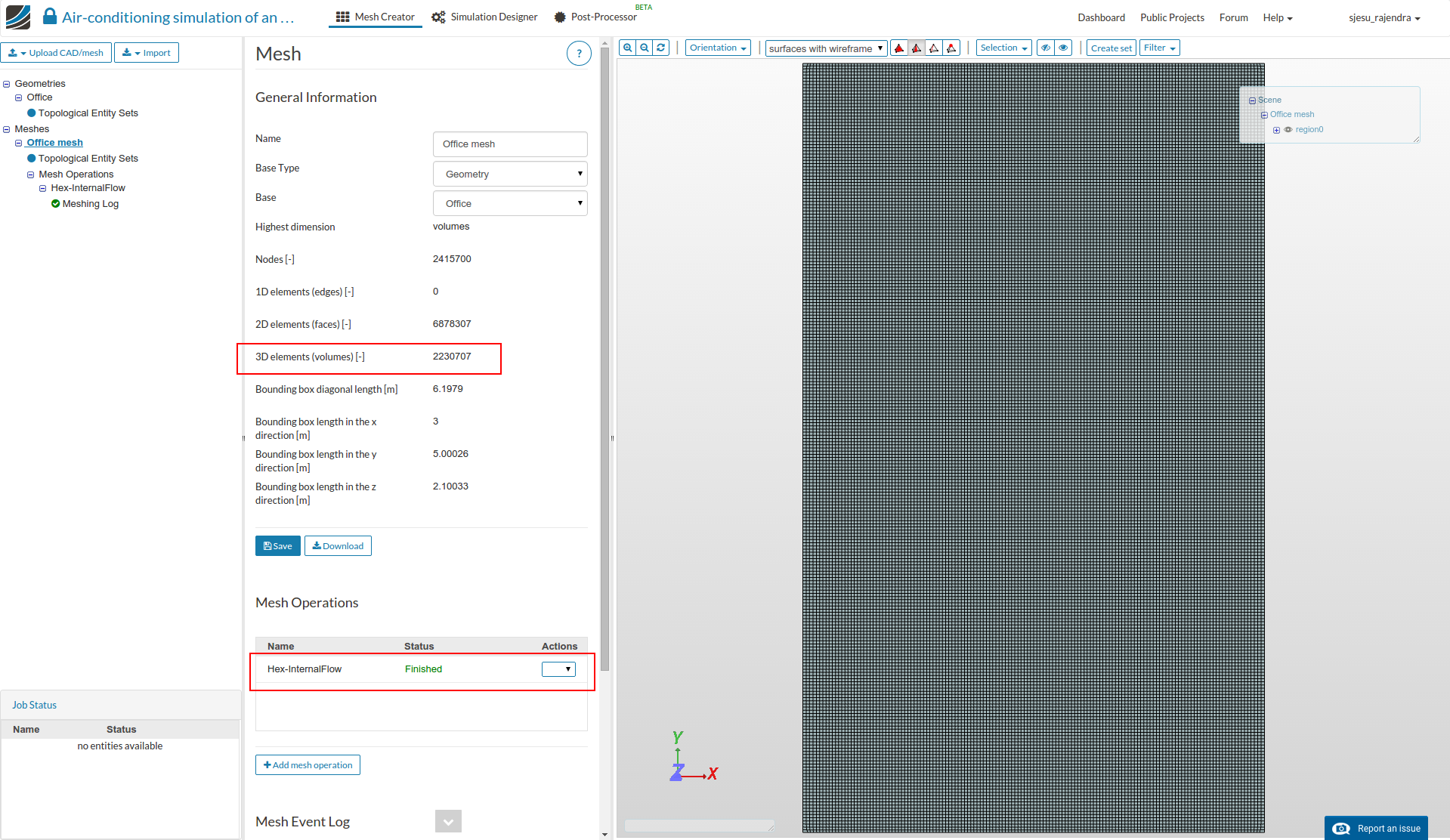
  • A message that the mesh operation is complete is seen in the left tab when the mesh generation is complete. It takes approximately 15 mins for the mesh operation to complete.

Simulation

  • For setting up the simulation switch to the Simulation Designer tab and select New simulation.

  • Change the analysis type to Natural convective heat transfer under Fluid dynamics. Select laminar steady-state type and click Save button.

  • The simulation tree now looks as shown below.

  • Click ‘Domain’ from the tree and select the mesh created from the previous task. Click the Save button.

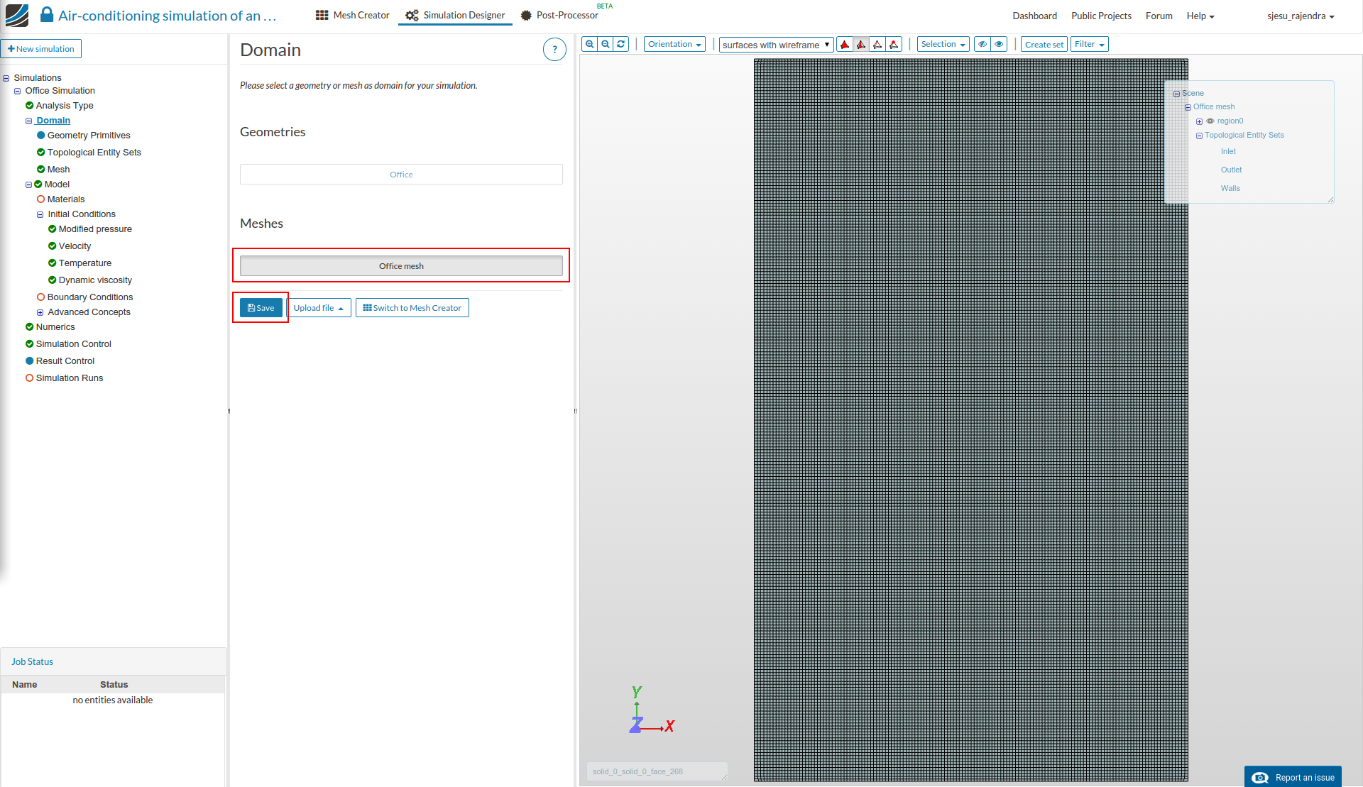
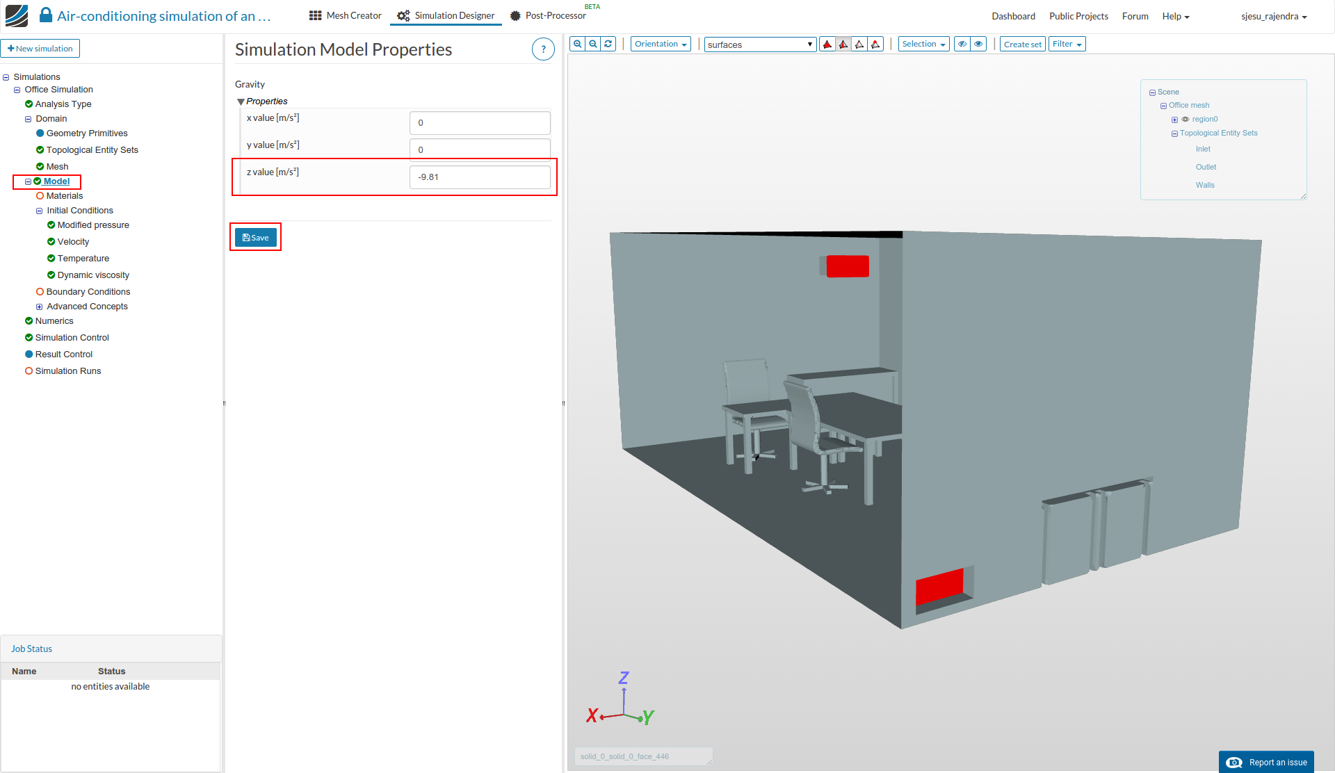
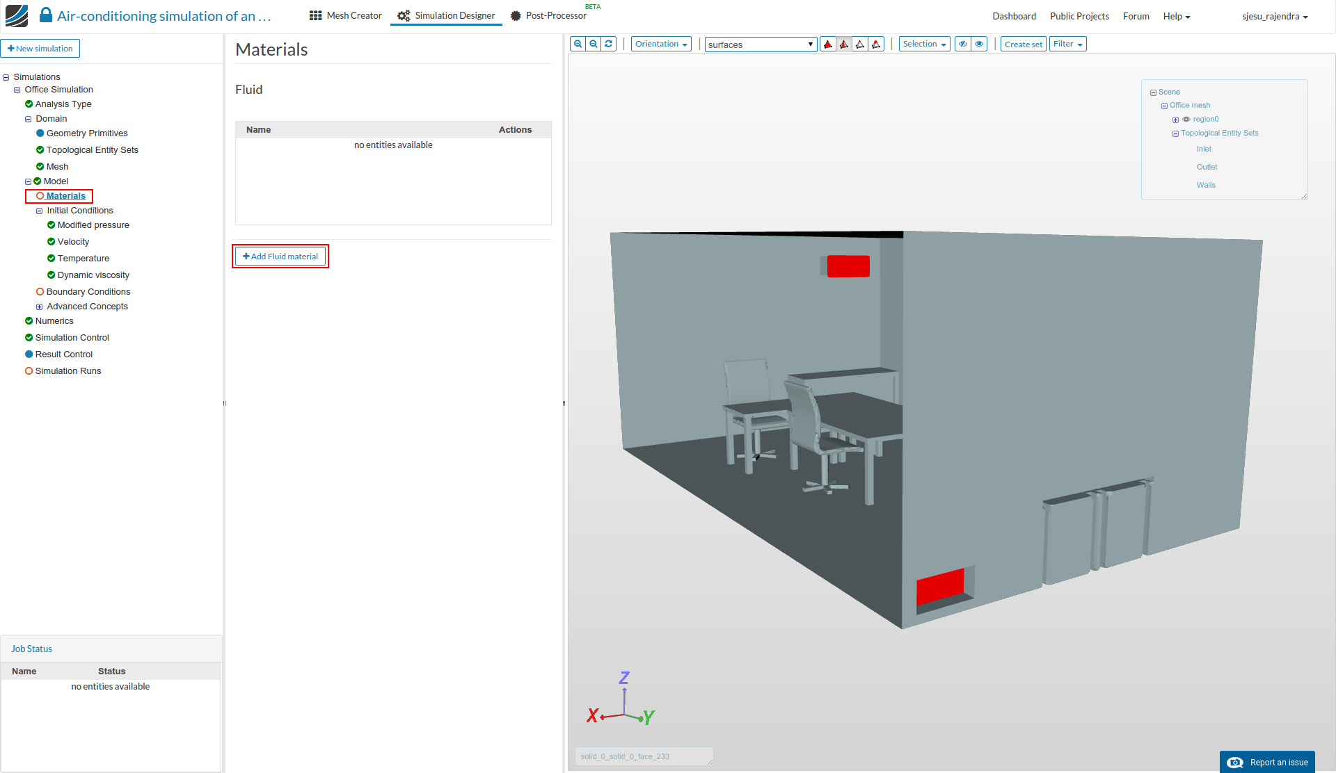
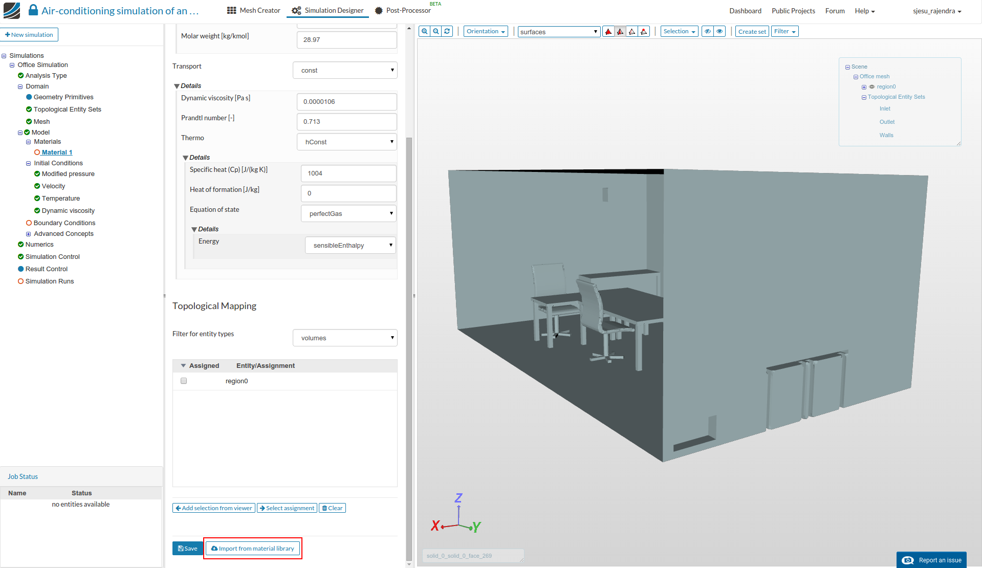
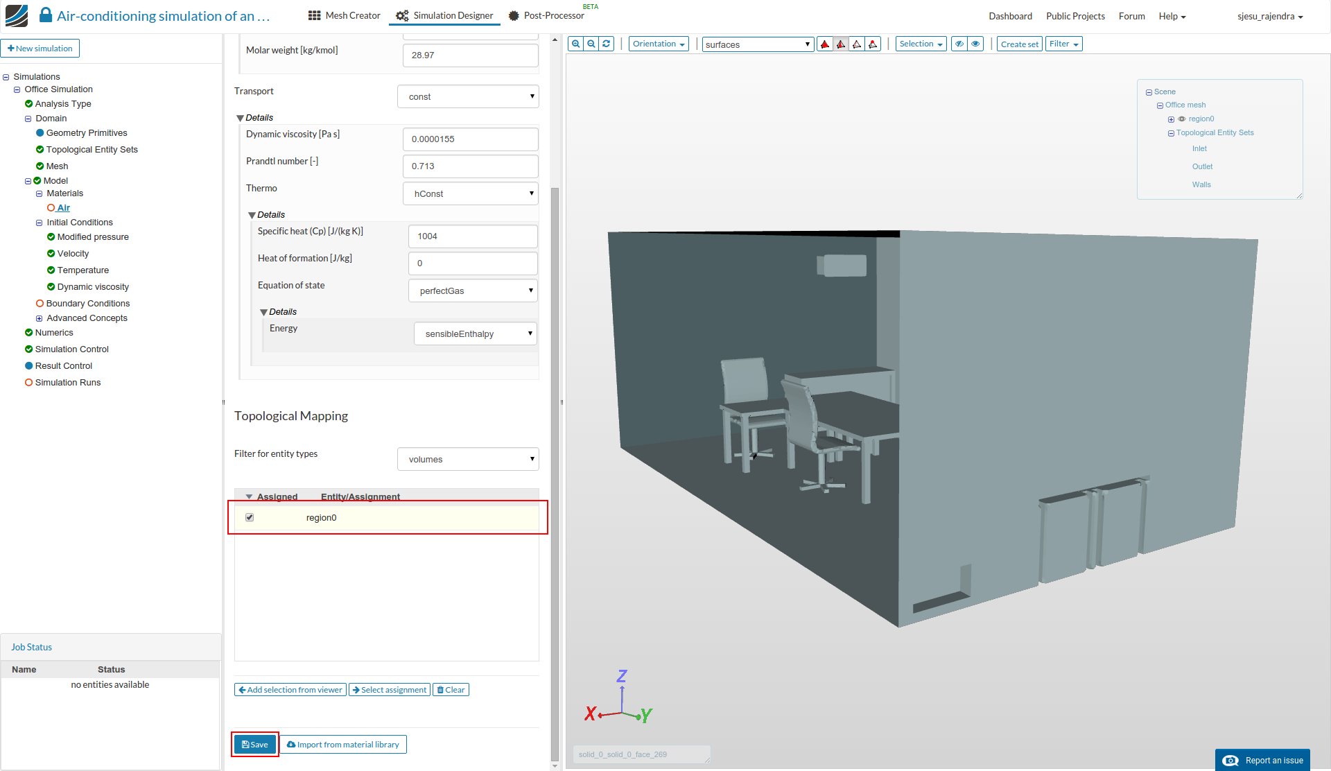
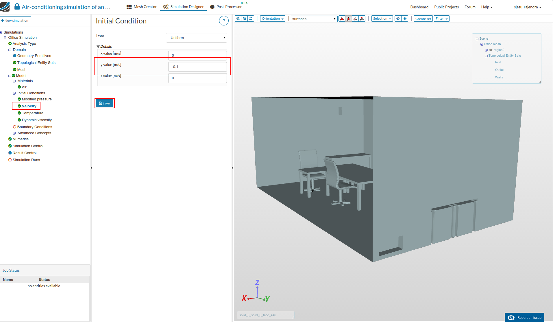
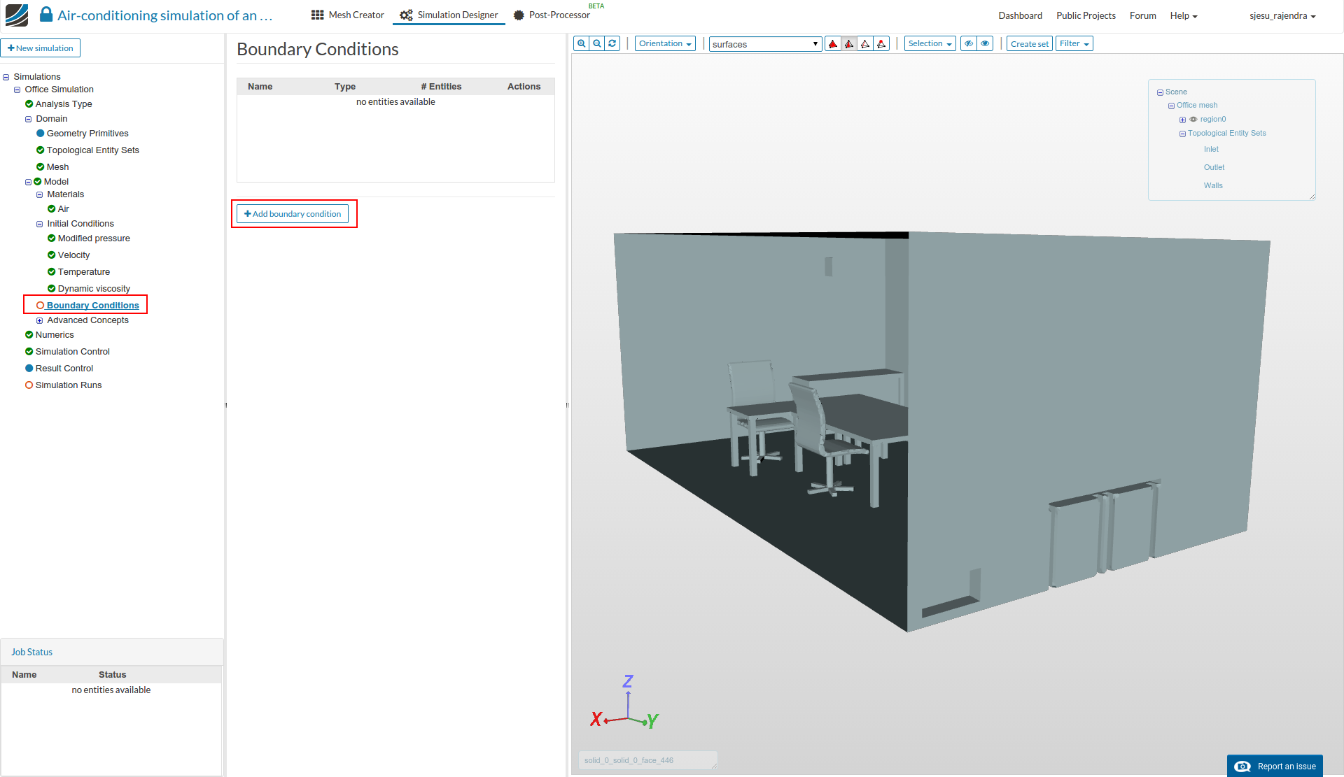
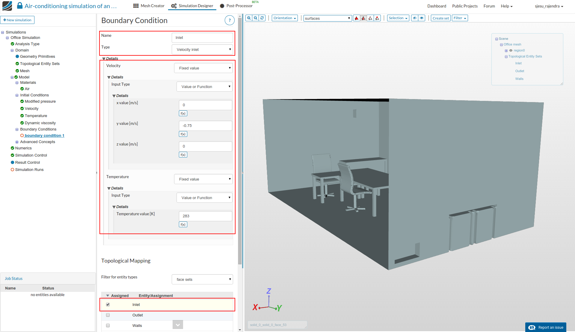
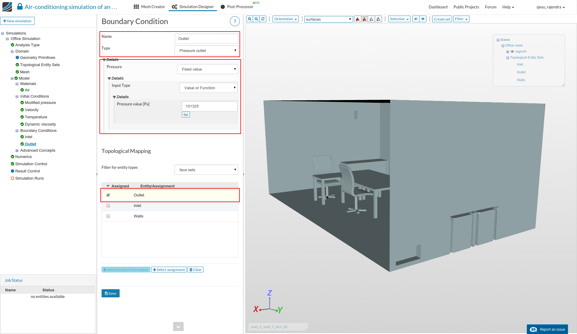
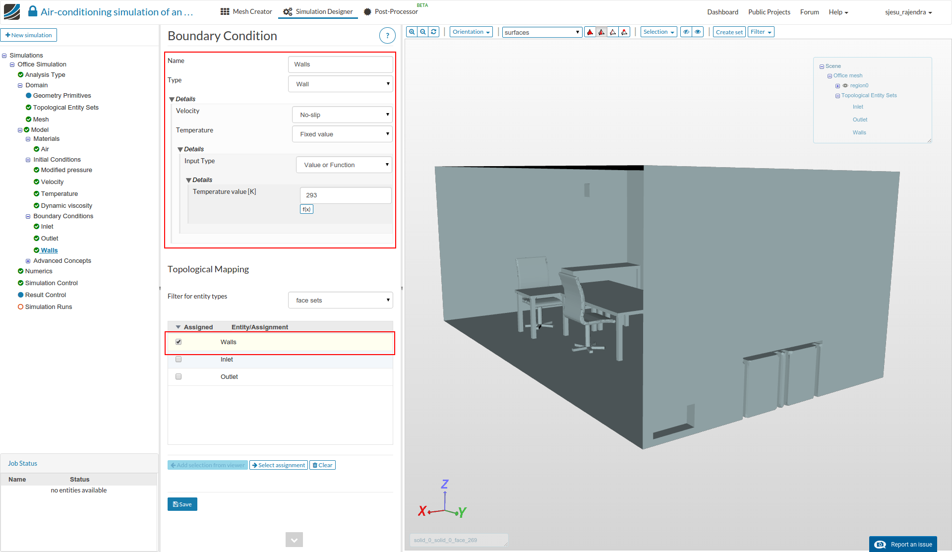
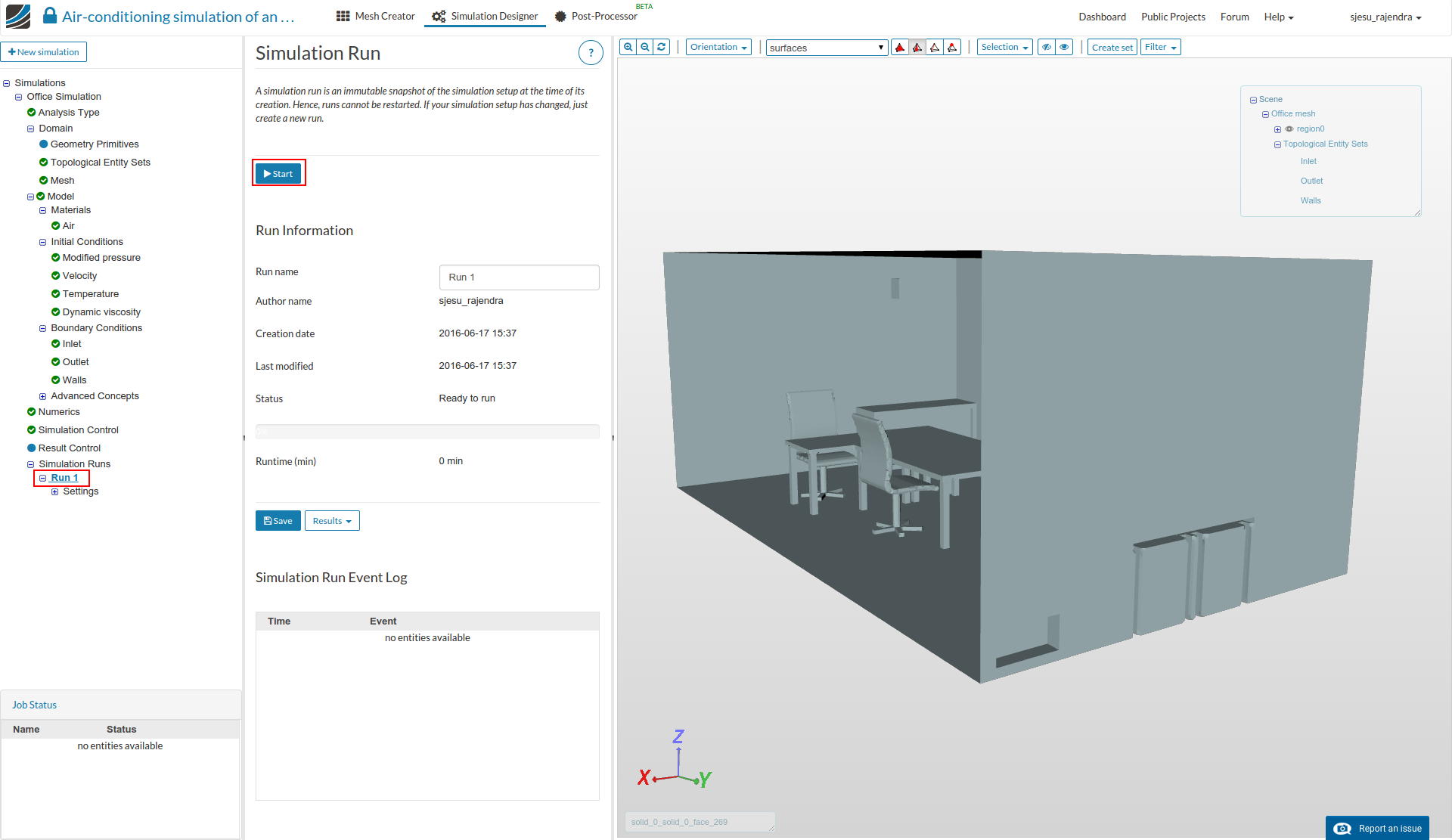
  • Click ‘Topological Entity Sets’ to name the different boundary conditions - inlet, outlet and walls, by selecting each surface from viewer and clicking Create entity set from selection for the inlet and outlet. For walls - select all the surfaces and remove the inlet and outlet selection.

  • Click on ‘Model’ and enter gravity value in negative z-direction.

  • Select ‘Material’ from the sub-tree and click Add fluid material.

  • Scroll to the bottom of the page and select Import from material library.

  • Click Air and select the Save button.

  • Select region0 from Topological Mapping and click the Save button.

  • Under ‘Initial condition’ from the tree, select velocity and enter a ‘y value’ of -0.1 m/s. Click the Save button.

  • Click on ‘Boundary condition’ and select Add boundary condition.

  • Enter the inlet boundary condition of y-direction flow at -0.75m/s and 283K. Select the inlet boundary and click Save option.

  • Add another boundary for outlet with pressure condition, as shown below.

  • Create another boundary condition for the walls at 293K.

  • Select ‘Numerics’ from the sub-tree and enter the following values. This enhances us to get the appropriate results.

  • Click on ‘Simulation control’ and setup the simulation run for 1000s time with a time step of 1.

  • Select ‘Simulation runs’ and click Create new run. Select the run and press Start button.

Post-processing

  • Once the simulation is over switch to obtain the results by clicking on Post-process results under Results.

  • Click on the solution field (‘Run 1’ in this case) and create a slice by clicking Add filter and selecting Slice.

  • Enter the values as shown below. Similarly click on Run 1 and create 2 more slices with the entries shown below.

  • The viewer looks as follows after the slices are created.

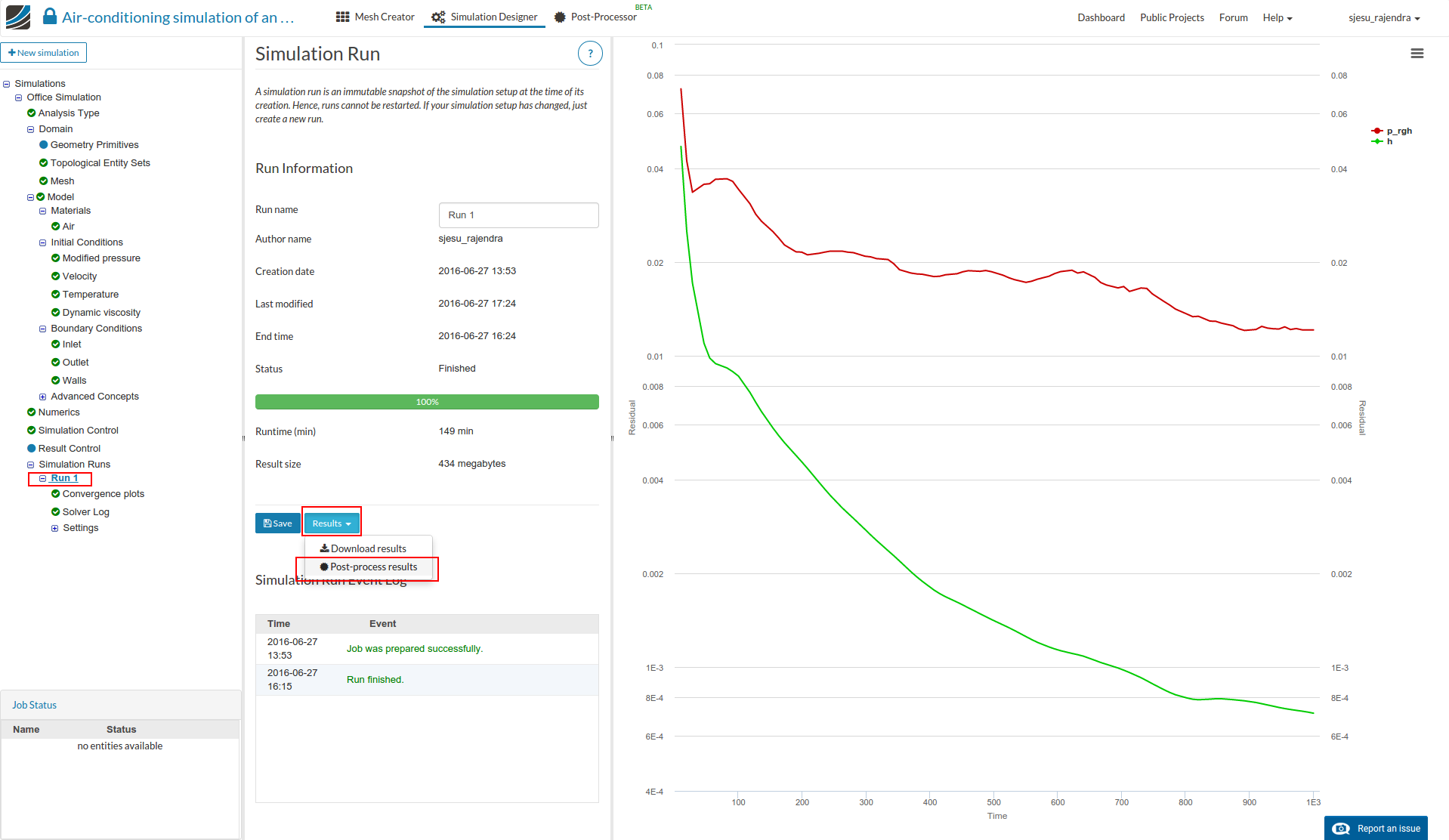
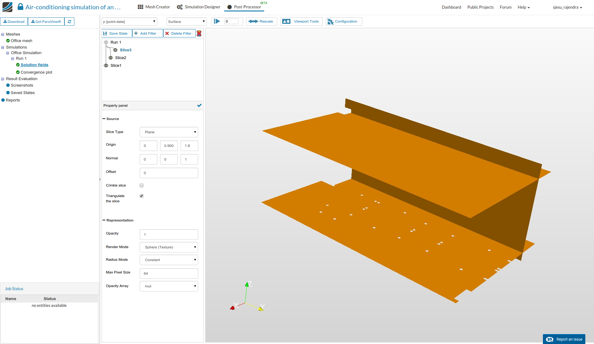
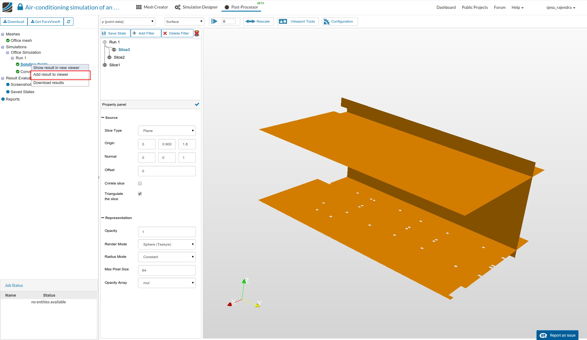
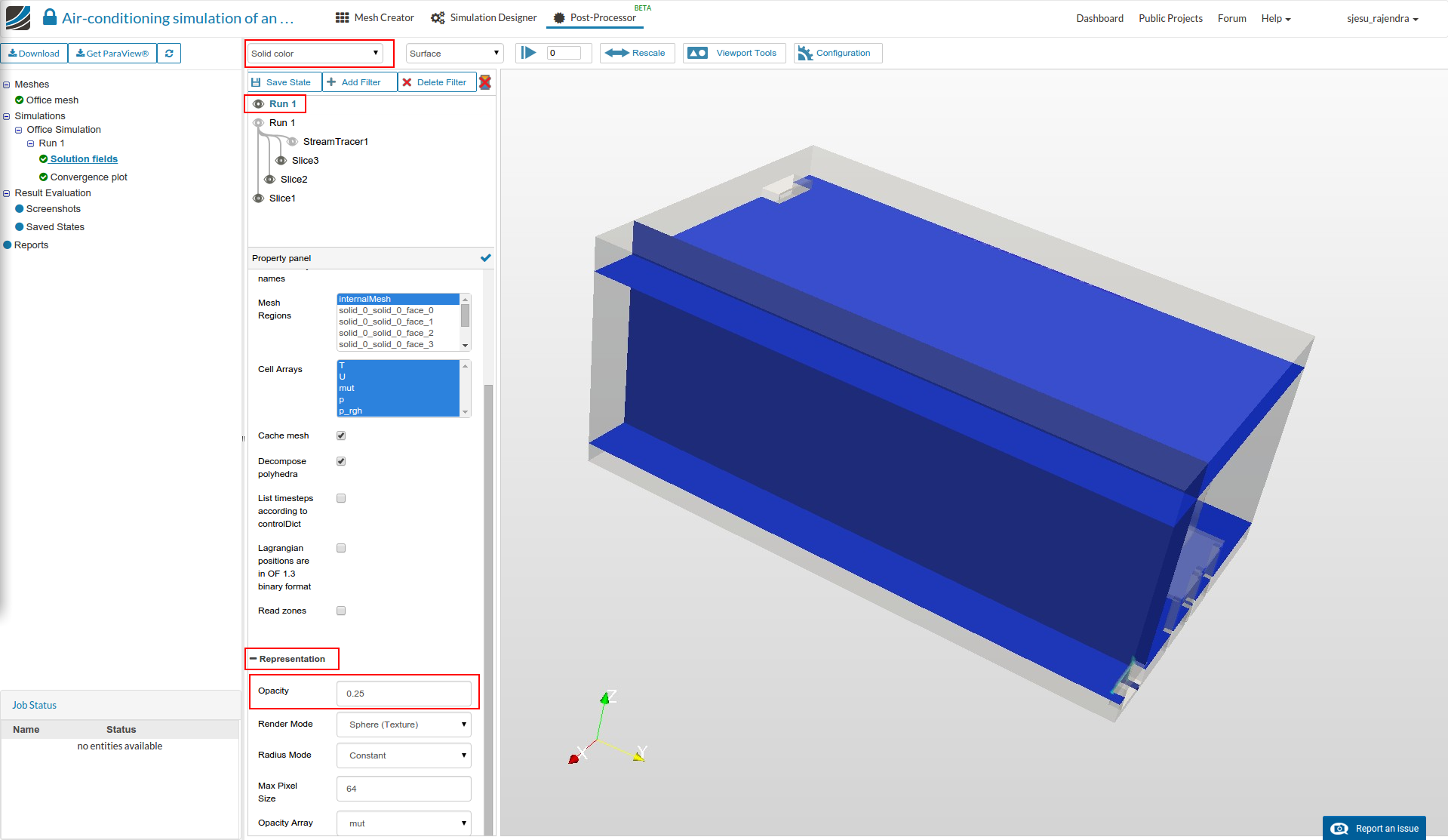
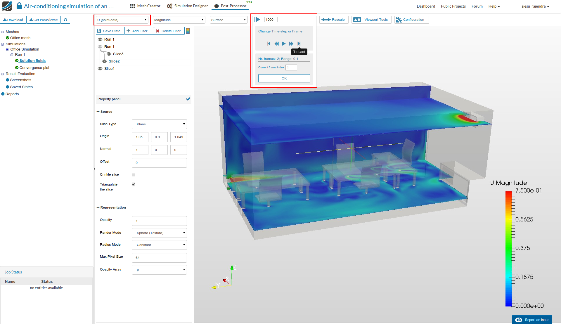
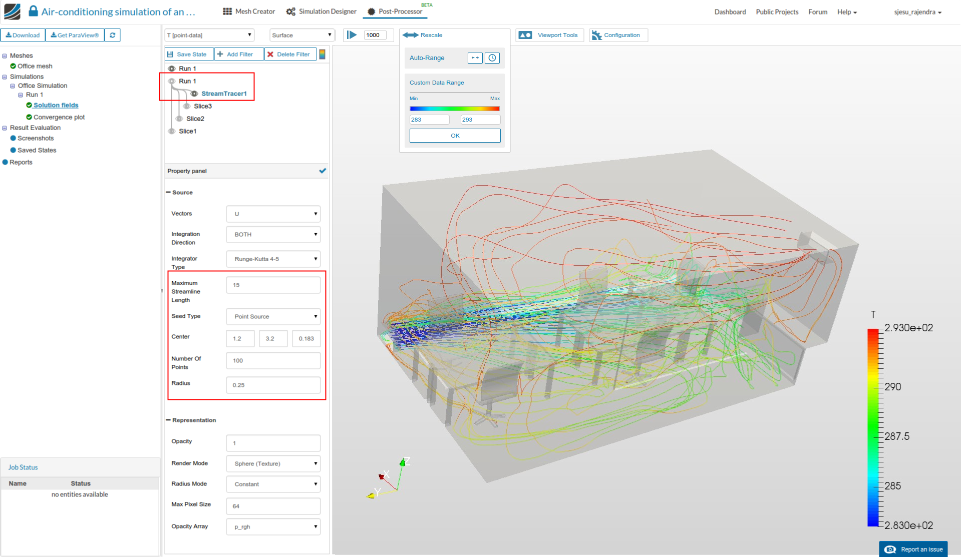
  • It might be interesting to add another instant of the region for better visualization. This can be done by right clicking Solution field and select Add result to viewer.

  • Select the new field and enter the following properties to decrease its opacity.

  • Select each slice and select the field to U [point data] to display velocity. Also switch to the last instant of time step.

  • A stream tracer is created to visualize the flow by adding another filter. Enter the values as shown below.

2 Likes

I’ve prepared something like @dheiny :smiley:

Interesting webinar, enjoyed it! :+1:

1 Like

@jousefm - ha, somebody was fast :slight_smile:!

To all workshop attendees: Thanks for joining today - feel free to ask any question you might be having here related to the session & homework!

Hi @jousefm,

You must be out of school for the summer! I have been enjoying your posts so far, keep up the great work!

Christopher

1 Like

Hi Christopher,

Thank you very much for your kind words! No I am currently writing my Bachelor thesis but writing some articles/posts besides that. :slight_smile:

Glad you like it and hopefully there will be more to come!

Cheers Mate!

Jousef

Hello Everyone,

I finished the tutorial this evening and I have a couple of questions for everyone.

First, when I went to mesh the Office CAD I got the following warnings in the meshing process.

The meshing continued and finished and it passed the mesh quality check.

My results seem to look like @jousefm velocity results and not @AnnaFless.


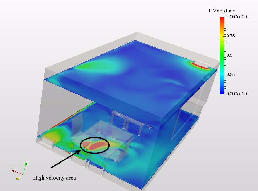
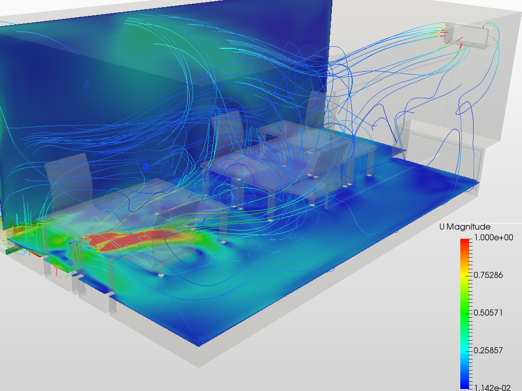
I am showing the highest velocity, not at the inlet or outlet as I would expect, but it appears under the table in a rotating pattern. I am not seeing anything that can cause this.

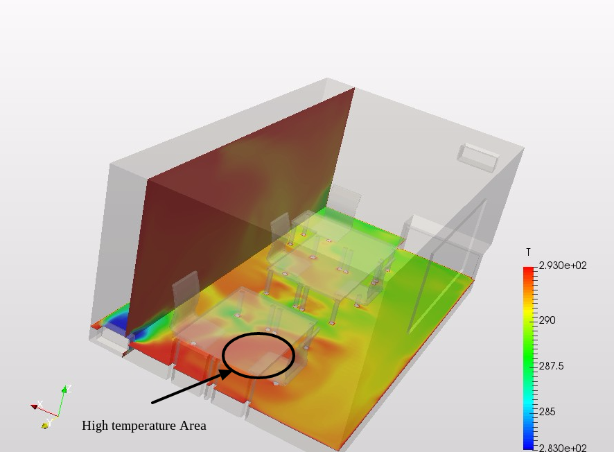
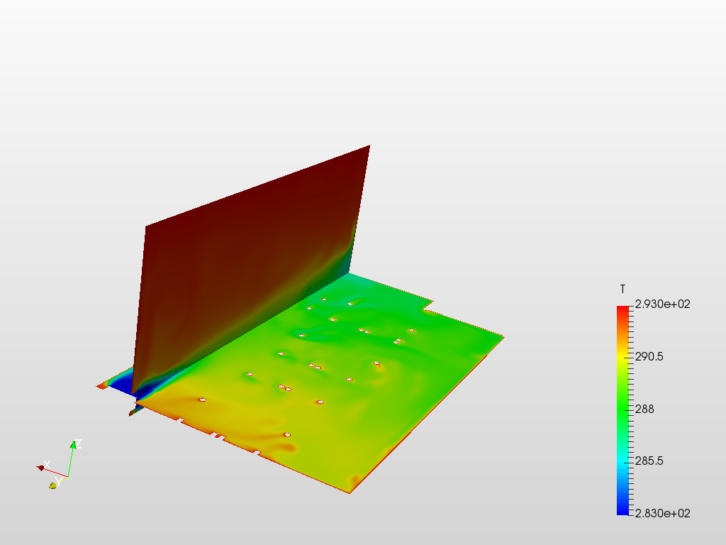
If I look at the temperatures, this high velocity area is also a high temperature area. I would expect the temperature to be lower where the velocity is higher.


I would expect the velocity to be similar to what @AnnaFless is showing, with the higher velocities along the back wall with secondary flows under the table.

Any thoughts? You can look at my project here if you want.

Thanks!
Christopher

@cjquijano - hm, interesting. @Ali_Arafat - you did the post-processing with this project, can you advice?

As a side note, for all workshop attendees - the data center cfd analysis project that we’ve done together in the workshop is now available over here: SimScale

1 Like

Hello Christopher (@cjquijano),

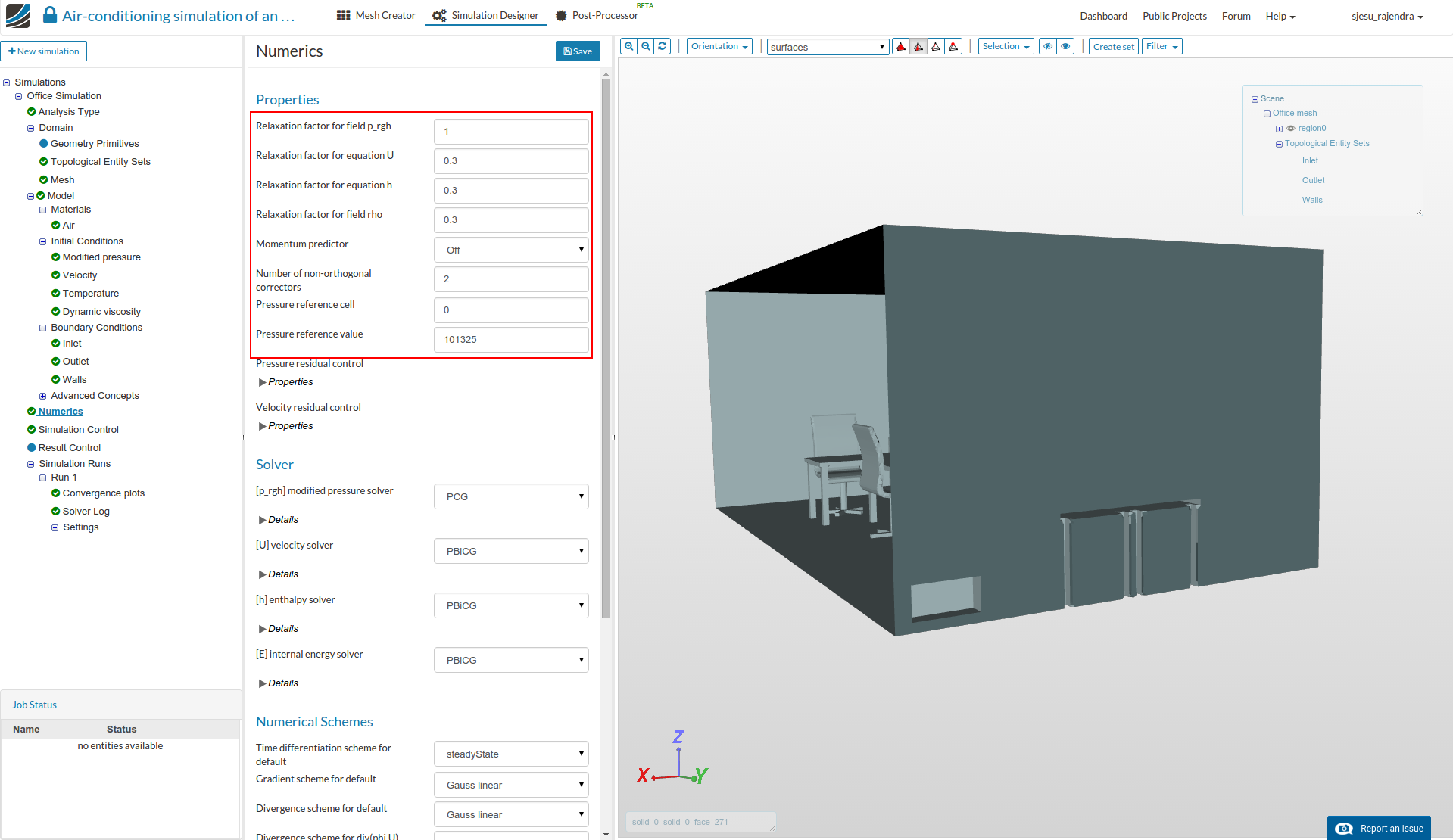
Great work. I had a look into your setup and the difference in the results is that we ran the simulation with Momentum predictor [in ‘Numerics’] turned off. It was a mistake in the tutorial that it had the setting with the factor turned on. The shown post-processing results can be obtained by changing this setting.

Momentum predictor can be usually used in order to get better converged results, which involves solving additional equations. We might get the similar results, to that of momentum predictor turned off, when we run the simulation for longer time and strict convergence criteria. Generally the momentum predictor may be turned on if the simulation has convergence issues.

The following result shows the temperature in the domain, with momentum corrector turned off.

Nice catch and thanks for bringing this to our notice.

Regards,
Sam (@sjesu_rajendra )

2 Likes

Thanks @sjesu_rajendra!

I turned off the momentum predictor and the results look as expected now.

Christopher

3 Likes

My meshing ends with an Error.
I got the same warning as @cjquijano and is was running trough bat at the end a error is happen.

@sburger, share the project link please :wink:

Thank you for your offer to help.
I did the meshing with cores and it went trough with the same warnings. I don’t know if the results will be the same but I expect it will be similar.
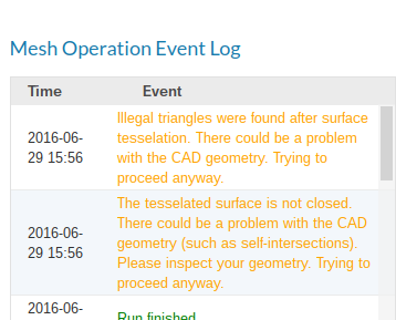
Anyway it is strange that the supplied geometry has a problem with meshing.

Next problem.
The simulation stops after 32s simulation with error. Maximum number of iterations exceeded. But I had it set up with 1000s maximum simulation time.
Project Link

Hello @sburger,

I just had a look to your simulation setup and seems like the run fails because of coarse mesh/bad cells, which might cause divergence.

A visual inspection of the mesh is always suggested to check if the geometry features are retained, and to check quality by avoiding bad cells. Try to create a ‘Moderate’ mesh and perform the simulation. In this regard could you please share the ‘Error’ which you got when following the tutorial procedure? I couldn’t find the error operation in the project.

Sam

Hi @sjesu_rajendra
I did start with the medium mesh and the meshing end with error. See above post.

Hello @sburger,

I was now able to create a mesh with fineness level ‘Medium’ using the geometry from the project link. Kindly check this project for the mesh - you can have this as a starting point to setup the simulation. Meanwhile could you please generate a new public link for the project which you shared earlier (the one which you shared has only a successful coarse mesh operation), so that we will be able to find the cause of the error.

Regards,
Sam

Hi @sjesu_rajendra

I did the medium mesh again and this time is was going through.
Yesterday it didn’t two times. I don’t know what was wrong because the log file had only warnings and ends with successfully work but still got the error.
Project

@sburger,

Thanks for reporting! Please save the mesh operation in future if similar thing happens - might help us look into the problem. Good luck with the tutorial and enjoy simulating!!! :wink:

Sam