How to mesh properly for rotating blade …error I got was : A multi-region mesh was assigned - this analysis-type requires a single-region mesh.
When does this error occurs…
Do I have isolate shaft if yes how…
My project is to calculate power, efficiency, torque and angular velocity for give flow rate of water at certain height…
How to simulate canal with head 1 m.
Is this project possible using CFD…
If possible give tip to avoid Any mistakes in cad preparation and meshing…
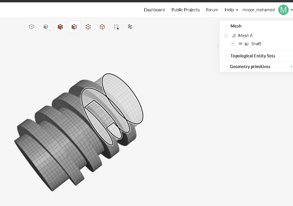
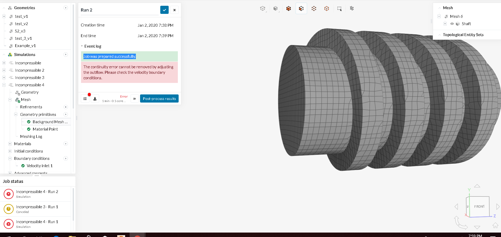
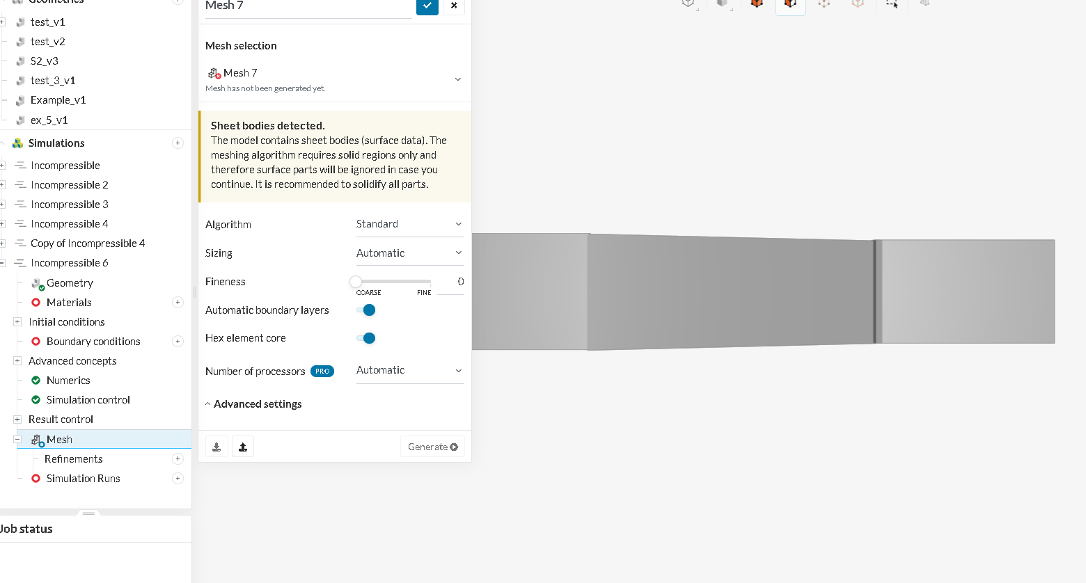
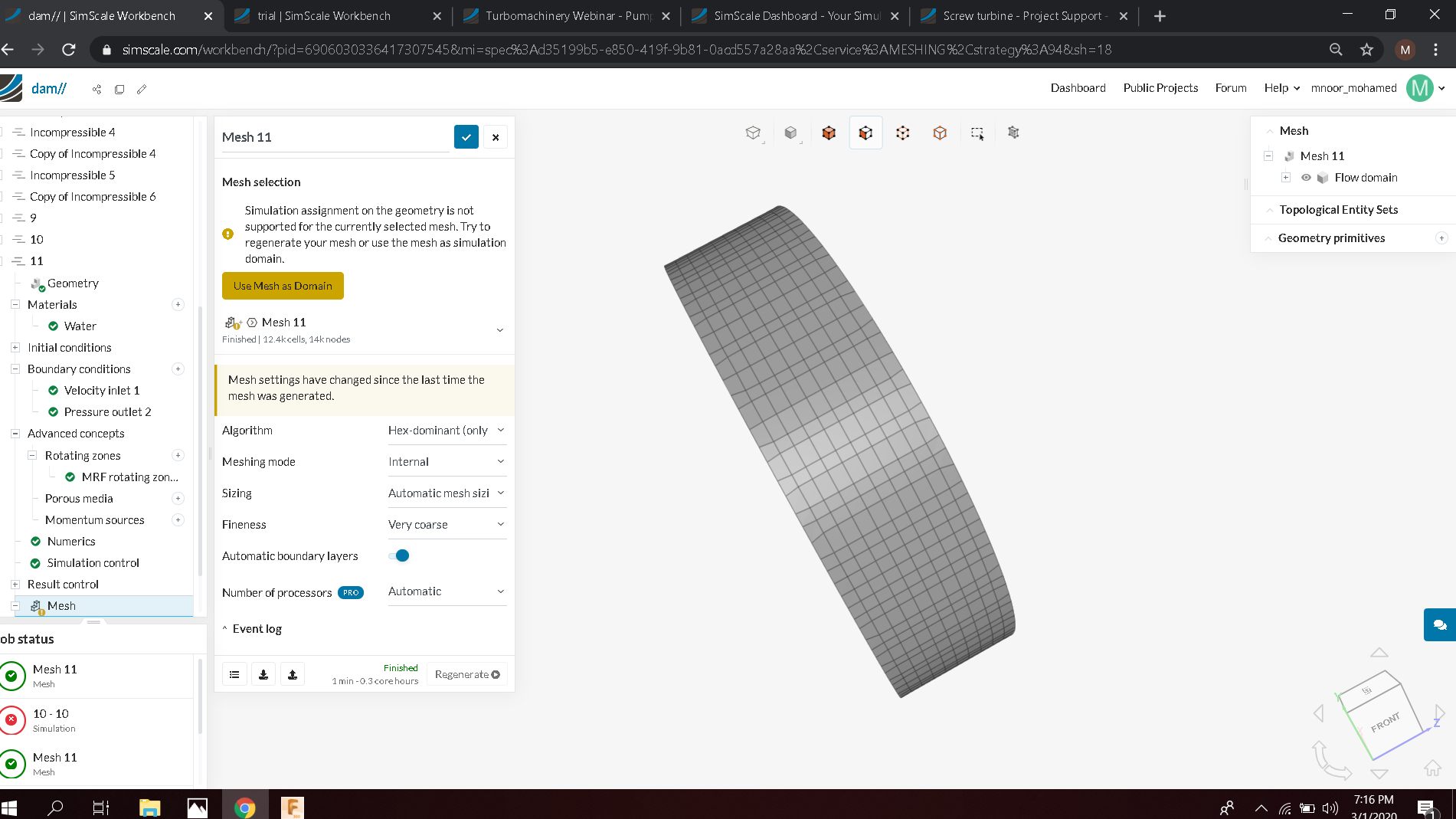
Thank you for the example. I tried and ran simulation.I tried to use simpler setup for by screw turbine shaft by enclosing it into region.And add 2 layers at inlet and outlet. I learned that inlet n outlet should be closed…so i add the layers…then the result was : Job was prepared successfully…The mesh generated result in image like this
The initial geometry was https://a360.co/35aZC7u.
I want simulate a screw turbine with head 1m and angle of 18degree. Is it possible to include this as parameter in cad modeling part ???
If you want it to be rotating, enclose the geometry in another cylinder (not too close to the geometry and not too far away) which can then be used for a MRF zone.
Just want to clarify if what i think is correct on how to preparing this cad model… constructing 2 rectangular tanks connected by pipeline with turbine shaft.
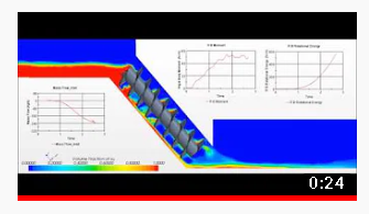
How generate graph for torque ??
Thank you very much for help.
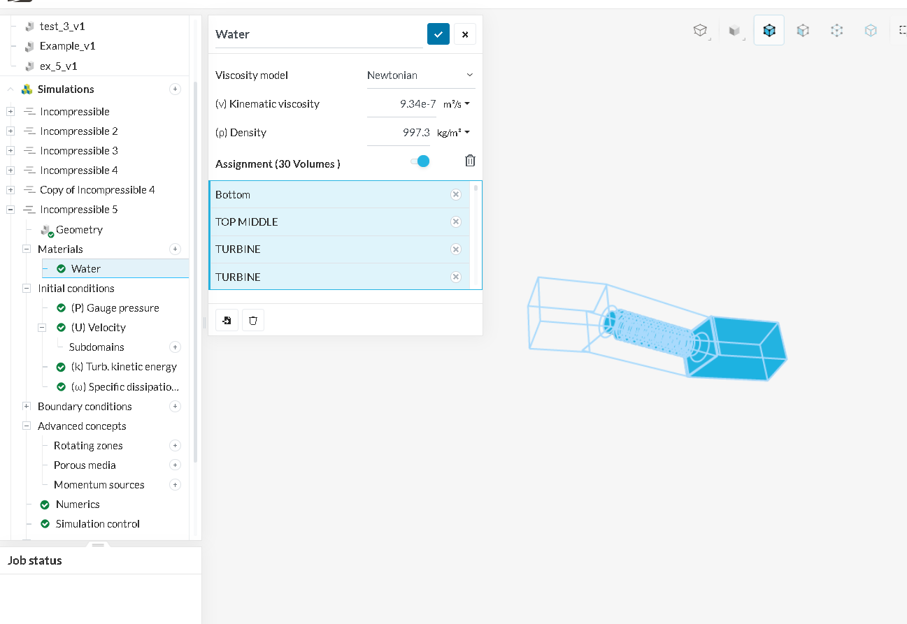
IS MRF ROTATING ZONE COMPULSORY FOR ALL ROTATING PARTS ??.if yes…1 doubt…should i select the faces of the blades only or both the shaft and blades of the screw turbine
In your CAD program, you need to create 3 solids first:
Simulation domain (where water would flow)
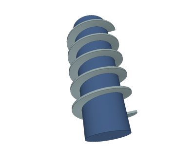
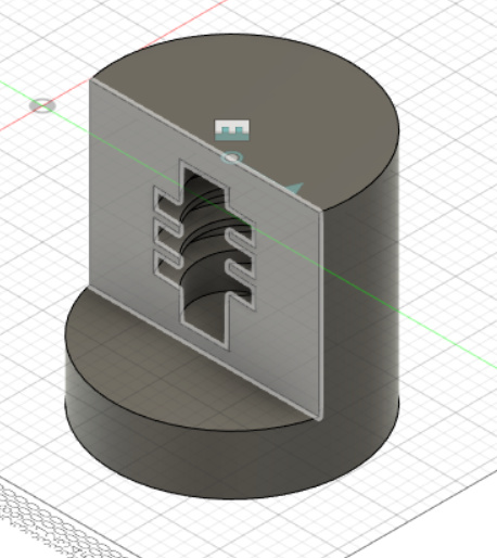
Archimedes screw
MRF cylinder which will contain your rotating screw.
But once ready, you have to remove (using Boolean operation) the Archimedes screw from your Simulation domain. You will be left with a hole in that first solid. That hole will have the shape of removed body.
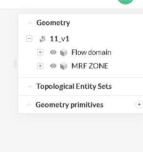
Now you are left with that new solid and MRF zone (total 2 solides). You need to import them into SimScale.
All those steps are described in Internal CFD with MRF project. You should read it again and perhaps make a copy and play with it.
Most of your questions will be answered after above exercise. Please be back once you are ready for your simulation.
Thank you very much @Retsam…I will do it just to clarify I would have to place the screw inside the mrf cylinder and and mrf cylinder would be inside the simulation domain…1 more doubt ???
do I have to keep end of mrf cylinder closed or keep it open like (hollow cylinder)
… i tried hexa dominant parametric because it was used in the turbo machinery webinar…i not sure what algorithm to use and how to define mesh refinements…can you confirm cad model and help me accordingly …
ok…i will try
I had support team ajitkumar help me with mesh refinements(mesh 5) …the mesh went well but simulation end in error ok multi mesh region being assigned …
Please now go to Result Control > Forces and moments and select geometry you have in your scope. You can also gather Surface data from your Pressure outlet.
SIMULATION IS SUCCESSFUL for the one without MRF zone which i started before i saw your message on adding it… i added the MRF Zone and simulated again …


 SIMULATION IS SUCCESSFUL for the one without MRF zone which i started before i saw your message on adding it… i added the MRF Zone and simulated again …