I’ve been tinkering with simscale off and on for a few months now stubbornly avoiding asking for help while spending hours and hours reading forum threads. It’s time for me to give in an ask questions!
I am trying to calculate several things related to a ducted fan setup.
- Theoretical thrust (done!)
- Optimize rudder design by calculating the steering force with various setups (currently stuck)
- Calculate the effect of flow straighteners on thrust (not yet started)
I am currently on step 2 and can’t figure out what’s going on. There are 3 simulations in my project. The first was step 1 where it gave me 304lbs of X force (thrust). I know this is high from lots of real world experience, but it’s in the ballpark and makes sense for a theoretical value.
Problem 1, plot units
The 2nd simulation is a copy of the first except here I have added 4 primitive rudders in the airstream. This took an eternity due to a super vague mesh error but I eventually figured it out. Looking at the pretty solution airstream it looks like it worked. But if I look at the force plots they are totally bonkers. I’ve gone from 304lbs of thrust with no rudders to 88,428! I figured this was a simple unit error but can’t figure out why it happened.
What kind of mystery unit is being used here and why did it change?
Problem 2, boundary setup
The 3rd simulation I tried changing the boundary conditions. The 2nd simulation setup was based on another member project with a custom “pressure inlet outlet” for the boundary box. The 3rd simulation I changed this to be more like one of the simscale demo projects with slip walls on the sides, pressure inlet in front, and pressure outlet on back.
My overall forces are in the ballpark with run 2, within 4% or so. Is one of these setup mehtods more “correct” than the other? I just want a stationary fan/duct in an unlimited volume of air so run 2 seems like the right approach but I’ve not seen that method used in other projects.
Problem 3, rudder forces
In sim2 I did force plots on the individual rudders using only the face in the airstream (between fan and rudder). In sim3 I did these using both sides of the rudder. In theory the back side shouldn’t be doing much. However, here is what I got.
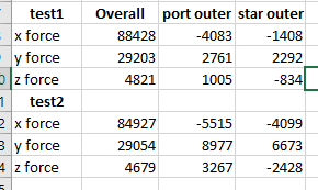
First, the numbers are a lot different. But more importantly, how did the x force on the one rudder go from -1408 to -4099? I know there is lower pressure on the back side so it generates some force, but it shouldn’t change THAT much right?
Next steps
I am currently doing another run on sim3 that separates the front and back sides of the two outer rudders individually to try and make sense of problem 3. It should be done in a few hours. I also added a “surface data” option for two rudders just to see what happens. I need to research this more because I don’t know what “surface data” calculates in comparison to “forces and moments” but I wanted to finish this post before I spent more time reading help docs!
Thank you in advance for any help you can provide!
Project link: