I have a CAD drawing for an air multiplier structure and I’d like to simulate the air flow through the structure and then how it impacts the external air flow as it goes through a Dyson-like air foil. Creating an Internal Flow Volume for the source of the air flow in the Dyson structure is easy. But it is meant to come out of an intentional 2 mm gap between walls and I get errors when I try to define the seed and boundary faces. The error is that they define an infinite flow volume. I can’t exclude them from an External Volume for very similar reasons. So, here’s my question -
how do I define the exit area for the internal air volume?
FYI, before you say that I have a gap in the drawing, I’ve gone back to the CAD drawing and ensured that all gaps are gone and that the various parts are just 1 space. I’ve even used the “Gaps” capability in the SimScale CAD package to look for gaps and it reports that I don’t have any.
Any assistance you have would be appreciated …
(NOTE: when I look at the ‘Dyson’ projects in the public domain, they aren’t complete or done to look at the holistic view of all air flows)
Hello @nrerup , this sounds a little tricky. To answer your question directly, exit area or any type of tolerance value is not specified by the user while extracting flow regions. This operation is only controlled by boundary and seed faces.
In order to help you better, could you please post a link to your project and maybe share some screenshots of your geometry? (locating the 2mm gaps, boundary faces of your geometry etc.)
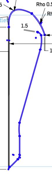
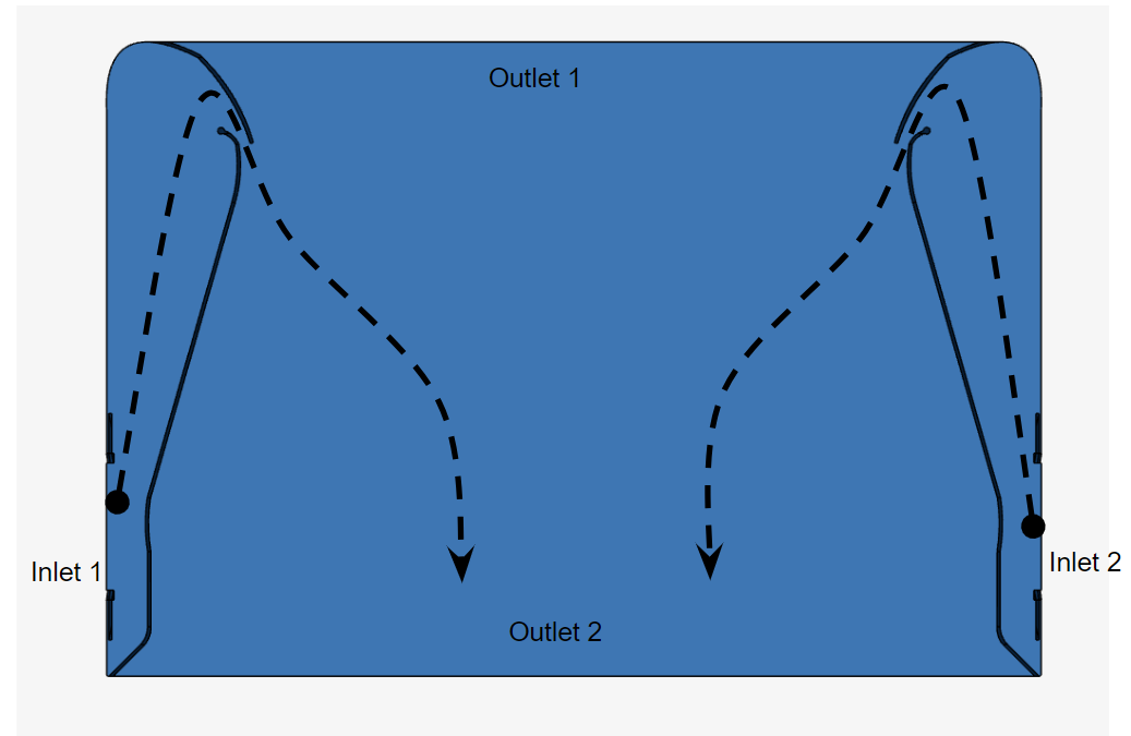
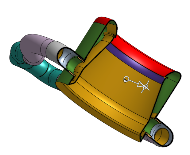
The attached image is a 2 dimensional drawing of what is then extruded with a revolve in Onshape. You’ll see the gap (imaging something like a paper clip in terms of overlap). The exit of the airflow comes through that gap, which is 2 mm in width. The input comes from a pair of inflow tubes coming from an air compressor into the body of the extruded image (as mentioned above. The difficulty is defining the seed and boundary faces of the gap. It’s easy to define the seed and boundary of the inflow area.
The link to the project is at Falcon Mach 1 by nrerup | SimScale
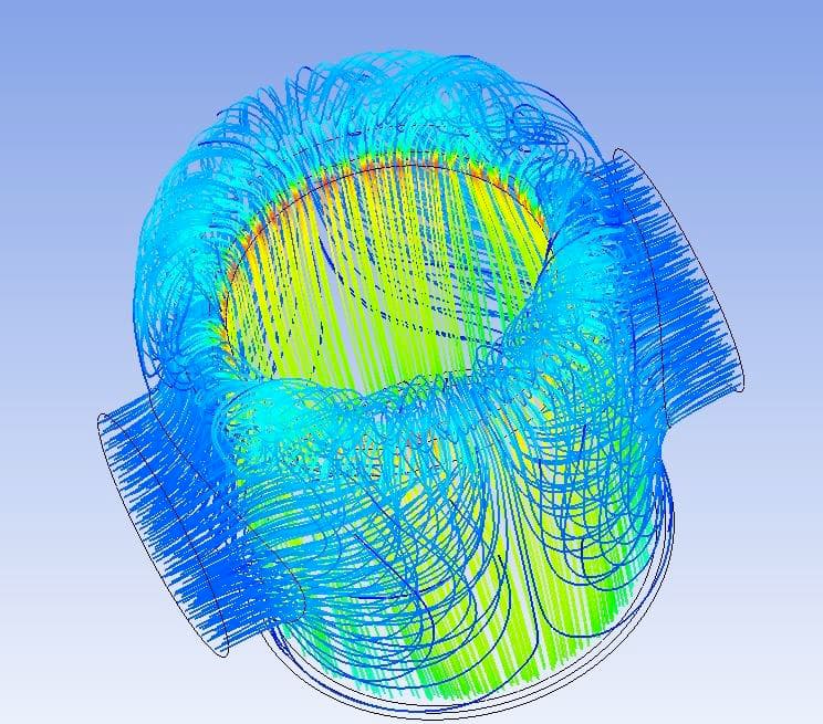
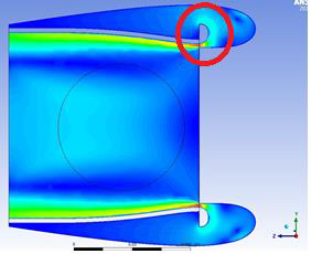
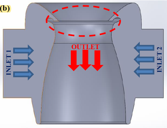
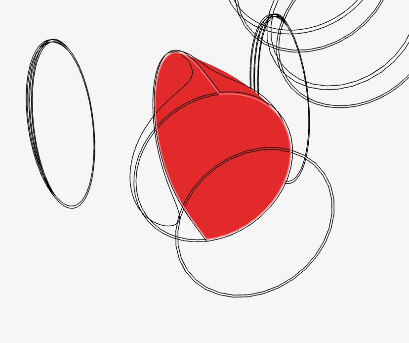
Additional information: The following images were taken from a whitepaper where someone had done a simulation and this should give an idea of what the result of the simulation should look like. The last image gives you an idea of the air flow that is occurring.:
Hello again @nrerup, thank you for the detailed description. I’ve tried a few alternative to generate the internal flow volume, however none of them were successful by using the flow volume extraction operation. It appears that operation fails to properly detect the adjecent boundary faces for the internal flow volume operation.
I was able to obtain the flow region as you described properly by following another workaround though. Here is the methodology I’ve followed:
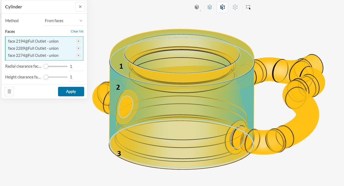
Create a cylinder by using From Faces methodology. This operation will generate a cylinder geometry that covers the selected faces. Please leave the clearance value as 1 since we do not want the boundaries of the cylinder to exceed those faces. Select three inner faces (to bound top, side and bottom limits of the cylinder) of the outermost shell of the geometry as shown below.
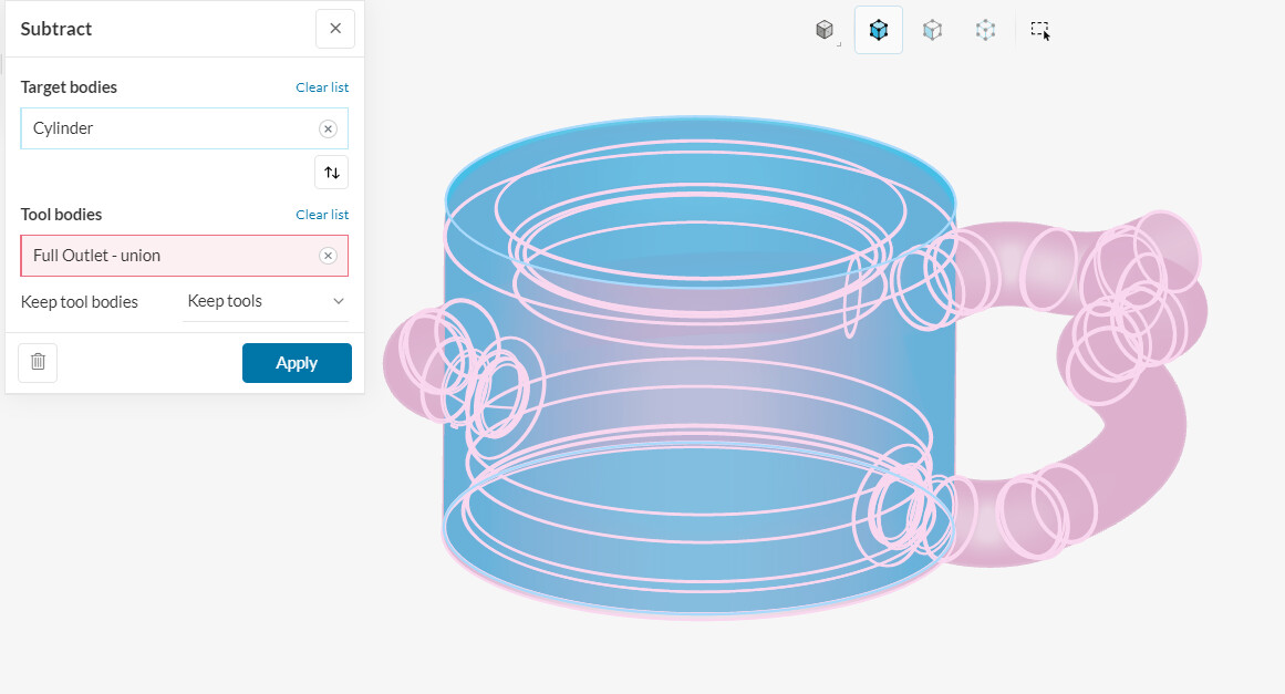
Use Boolen/Subtract operation to subtract the main geometry from the cylinder and to divide the cylinder body as shown below. (You can keep tools at the moment)
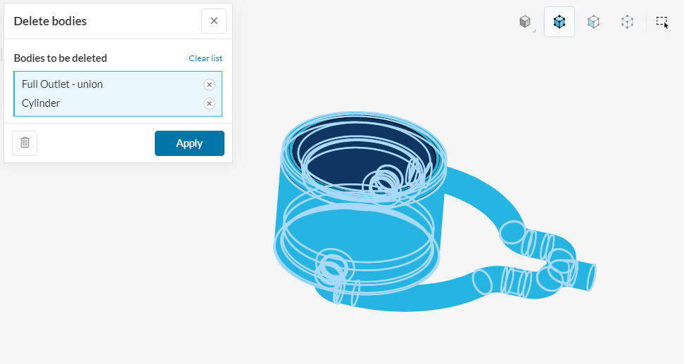
You’ll see that cylinder geometry will be divided into two bodies. Delete unnecessary divided part of the cylinder at the top corner and your main geometry by using the Delete Body operation.
Just to visualize the inner domain properly, you can temporarily split the flow region in X direction. This should give you a clear idea of what you obtain in the end.
Please keep in mind that I haven’t dealt with the pipe geometry in this scenario. Feel free to create separate internal flow regions for the pipes and use Boolen/Union operation to o unite the flow regions. However, the pipe geometry seems a bit problematic, probably one of the reasons that internal flow can not be created. There are two openings where the pipes are connecting to the main geometry, and entrance of the pipes seems like sealed. Please check those parts as well, in case you want to include the flow in pipes to solution.
Hello Neil, I see your point. Then the question here where you want to model the inlet boundary condition at. In case you have the inlet conditions at the connecting plane between pipes and main geometry (mass flow rate, velocity, etc.), then it’s better to remove the pipe geometries to reduce complexity.
In case you only know the flow properties at the begining of the pipes, then you should create a separate flow region inside the pipes. However this will be a little tricky. Now that we know the opennings at the end of the pipes are intentional, these opennings should be modeled as outlet boundaries as well.
Whichever methodology that you like to follow, I’d suggest you to start simple and add complexities one by one. This will make it easier to track the possible errors.
About the blockage, this is the blocking face as I’m able to see in the geometry.
Please let us know how it goes with these suggestions. In case it’s successful, please don’t hesitate to share your results, that’s a pretty interesting application, thanks!
Thanks Kaan. Thats what Im doing now, reducing the simulations to 2 separate components. I see this morning that the main body simulation completed so Ill go overnit in a few hours. My concern now is if the issues I see are due to the simulation or the design. But I deal with it as I go - I saw hints in the original failed simulations that the design will work.
Hey Kaan, I’ve run the simulation and I see the air flowing the way I’d expect except for 1 thing. I think that the ‘by face’ method created caps to the external environment from the top and bottom of the body. The air flow acts as expected from my pre-defined inflow at the sides of the body (the Coanda effect) but the inducement and entrainment of the external air sources aren’t included into the model. The result is that the simulation acts like a ‘turbulent’ field is occurring within the body whereas what ‘should’ be happening is a flow through of air from top to bottom along the Z axis, multiplying the air flow from the inlets.
Suggestions on changing the cylinder shape? Possibly increase the clearance to 2 from 1 to allow for the air flow from outside the body through the body?
FYI, Test Run 4 ran fine after I changed the setting to take into account the Mesh quality.
Hello again, @nrerup ! Your suggestion to create a larger cylinder makes sense in case you want to examine the whole interaction of the flow around your structure as well.
That leaves us the question of how we should define the boundary conditions for cylinder surfaces that will represent the atmospheric conditions. In this case, custom boundary conditions might be helpful. I’ve created a custom boundary condition for three surfaces of the cylinder to mimic the atmospheric conditions. Streamlines show that boundary conditions makes sense, but it’s better that you check yourself since you’re experienced with the application.
You can set the velocity type to zero gradient which will equate the interior velocity values inside the cell to the boundary faces. Since we don’t have a clear idea of the flow direction everywhere, this will represent the atmospheric conditions while allowing the air to pass through in or out.
For the pressure type, you can set fixed value with 0 gauge pressure in order to specify the static pressure of the environment.
For the turbulent variables, you can use inlet-outlet condition type. Inlet-outlet condition type allows users to specify certain variables for inflow situtation. In case of outflow situtation, zero gradient is applied to the selected boundaries.
Also, please double check the velocity direction for the velocity inlets. Since the inlet boundary direction is not very clear, you might want to use a flow rate option for the inlet. To improve the mesh quality, increasing the small feature suppression value may provide better results.
Please let us know how it goes, and don’t hesitate to share your results.