hi everyone,
I was done with my RUN so for further understanding I downloaded the results from the respected run.
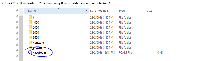
when this file is extracted and there is one case file which has 0 kb and this file not open in paraview software. I was faced similar problem coupled of a week ago.
hi sir,
can you do one thing for me?
please download these results and extract the file and see can there is the same problem?
if not then please share only case file with me.
thank you,
Rohit.
HI SIR,
thank you for the reply.
the problem in my software but now its work very well.
this wing was made in SolidWorks software and it looks like Mercedes
but everyone knows Mercedes face some problem in winter testing (more in the front wing )
ferrari work very well this year
thank you for your support and I will require more help from you in the future.
thank you,
Rohit.
Oh? Did you make it yourself? It looks really good. I would be interested in how you made it.
Yes they are having issues. Their end plates were in washing into the tire. I believe they hoped that a small vane on the side of the wing combined with the in wash endplates would be able to increase vortex strength and carry the flow over the whole wheel via that vortex. That didn’t seem to work too well and affected the package as a whole, so they now changed their design and the end plates point outside with a cut in them to also generate that vortex. Very interesting in terms of the development.
Yes and Ferrari look super strong with their different wing profile.
hi sir,
sorry for late response.
as i said i want to check force on front wing when DRS was not activated and when DRS was activated so, for that i had made two simulation at 300kh/hr and 350 kh/hr.
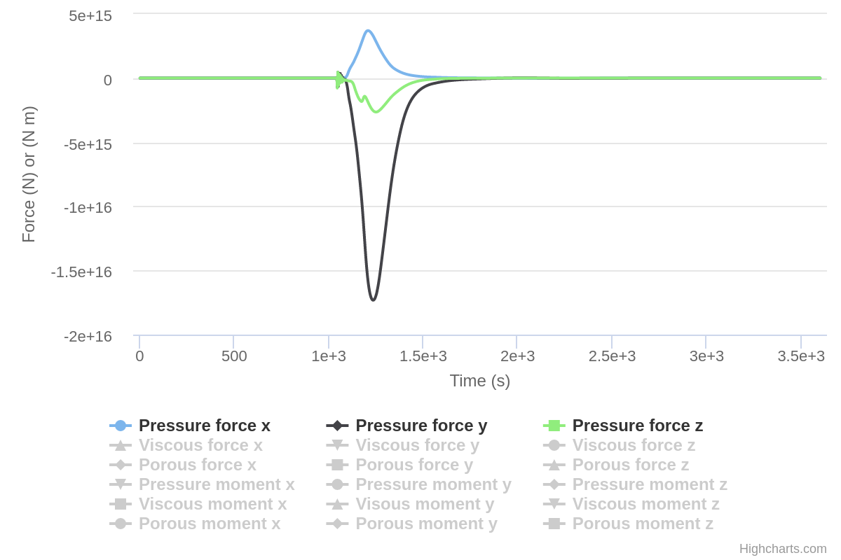
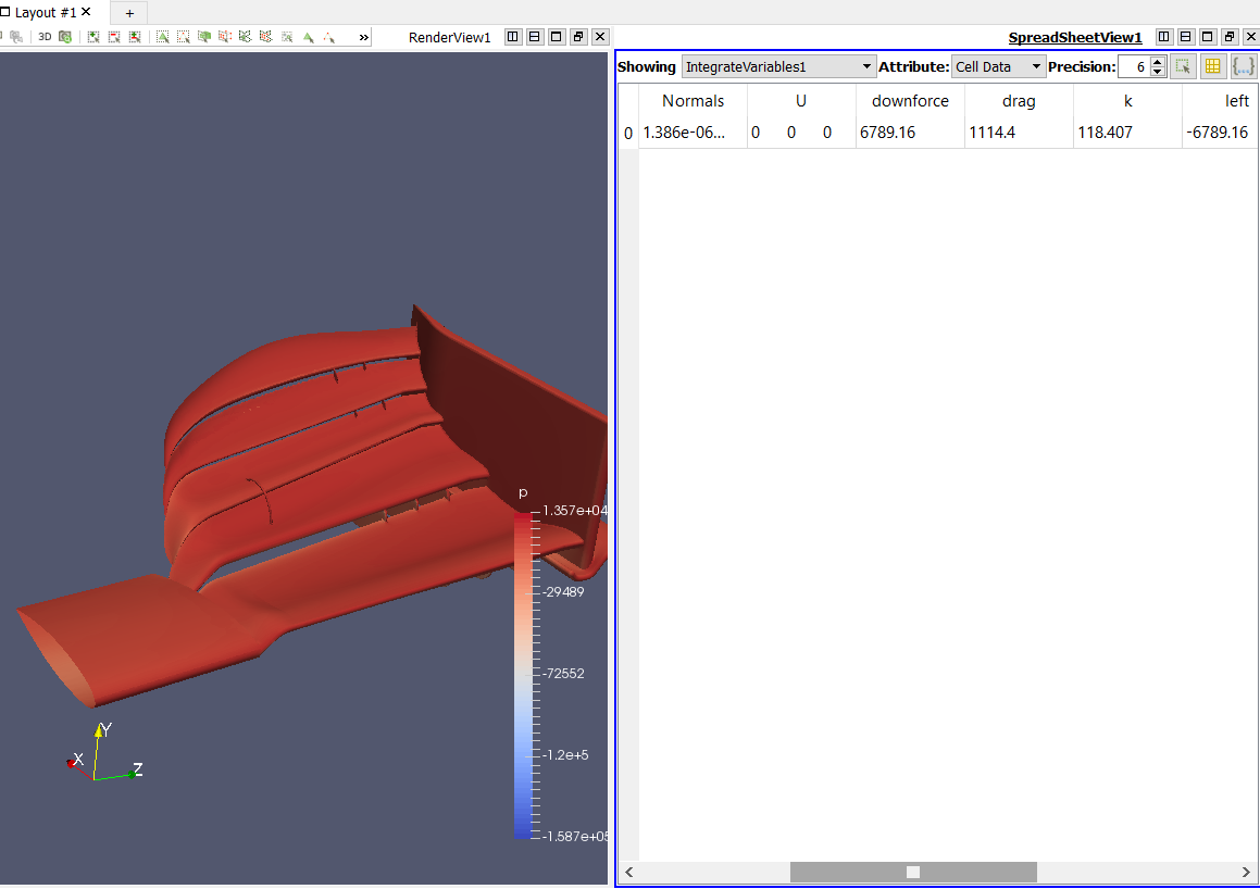
i got one value from force plot and its 1.5e16 in downward direction but its totally wrong.
please help me to find the problem.
in simscale
for force n momentum i had selected all front wing part.was this the right step? ( in results got 1.5e16 N value) https://www.youtube.com/watch?v=DZhZPQZS-zE
hi everyone,
above problem occurs when U=300kh/hr.
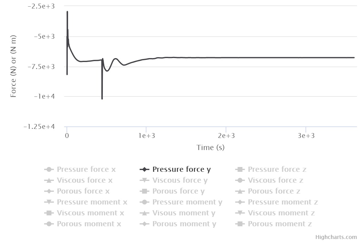
when I was simulated this with 350kh/hr (trying to find down-force when DRS was activated and when it’s not) then got the realistic value there is no problem on simulation.
Sorry I meant to get back to you on this but am rather busy this week!
Try disabling potentialfoam initialization and re-run the sim at 350 kph and see how it goes.
If that still causes problems, try setting a ramping inlet with a csv file and gradually build up the speed in increments of say 10 kph over 300s to 350 kph for a total sim time of 1500s or so. This might better improve the results.
I looked at your project and saw some quite quirky things happening in your simulation.
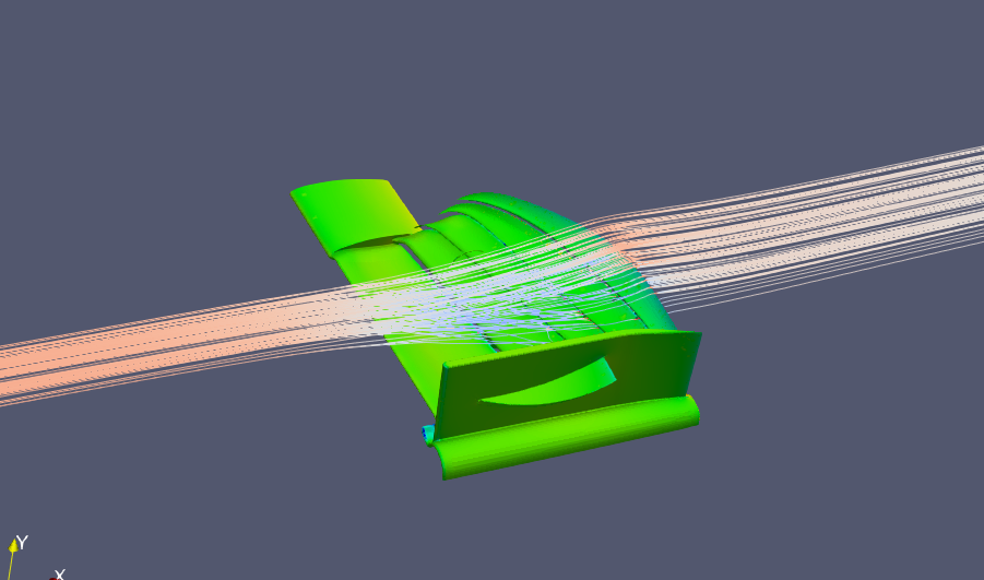
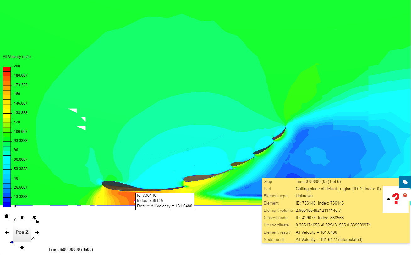
You are running an incompressible simulation but the velocity in many areas was way above 120m/s. Here is the cutting plane that shows “all velocity” of your 350Km/hr case.
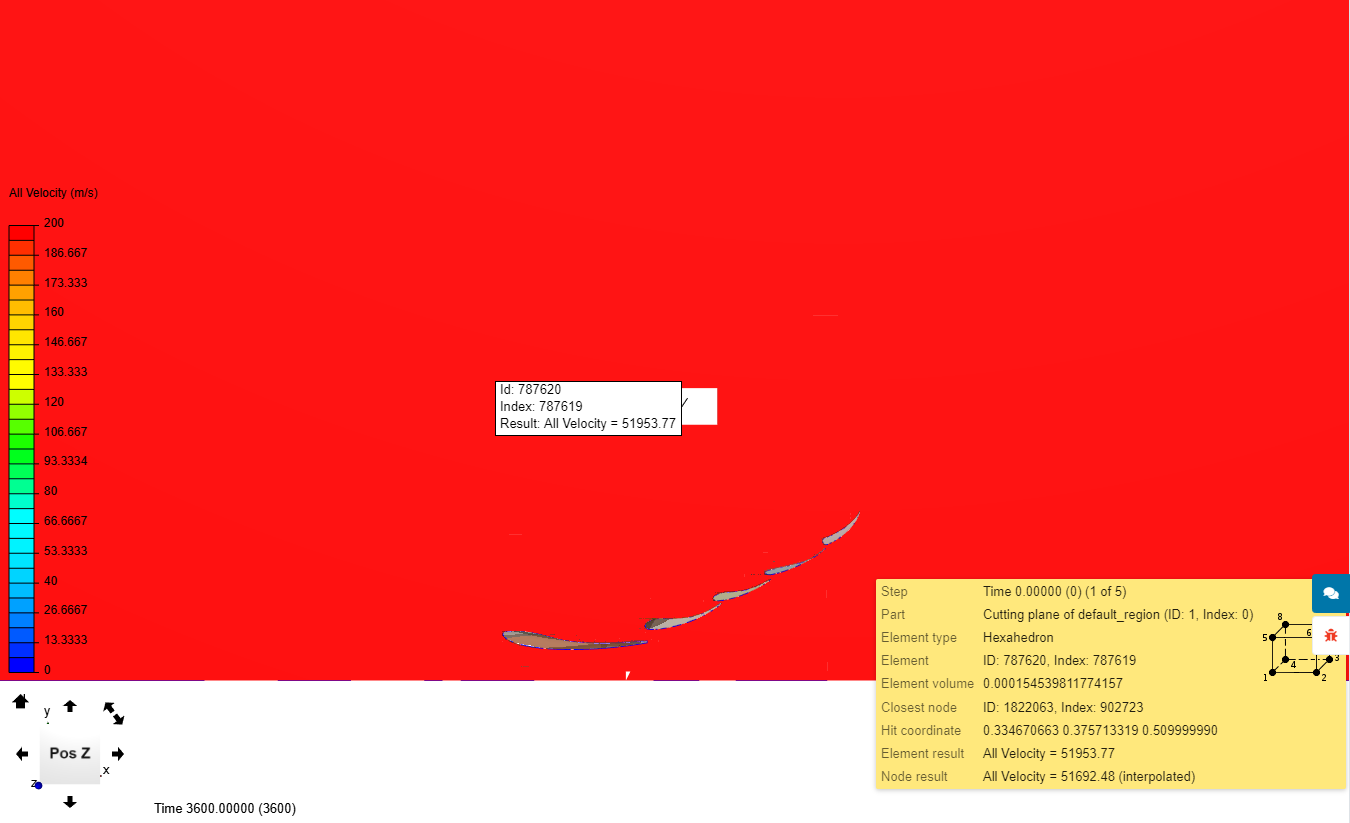
The other simulation made with inlet vel. of 300km/hr is showing a very strange behaviour(It has not converged even after 3600 iterations) and when I post-processed the results to get the vel. distribution on the cutting plane, this was the result-
I will take a closer look at the numerical schemes used in these simulations and would run the 300km/hr case on my laptop and respond if I am getting the same results or not. But at present point I cannot give any info regarding this strange behaviour even when they were using the same settings(except the inlet vel.)
hi sir,
i don’t know about disabling potential foam and how to set & were to set in simscale .
i will try ramping inlet with CSV file but again sorry i don’t know how to set this value U ,U ,U. Do you have any reference for this topic?
hope i will complete this before the race will start on Sunday
i will show you another f1 part simulation tomorrow. hope you like it
thank you,
rohit
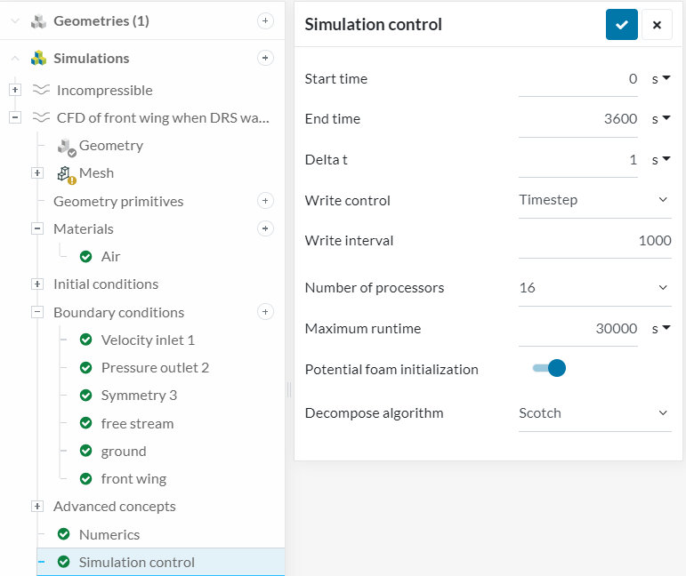
Potential foam switch. Go to your simulation > Advanced concepts > Simulation control > Potential foam initialisation.
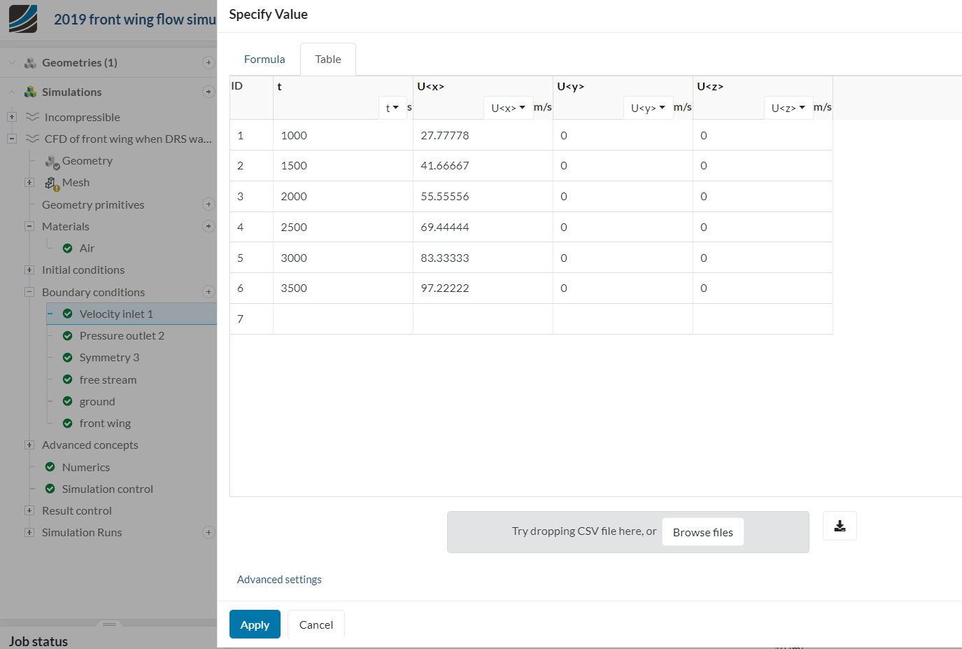
Ramping inlet velocity: Go to Inlet definition > Click on U (velocity) small icon on right side > drag your CSV file in > check that first column is defined as 't' (time) after upload of CSV is done.
2)for Ramping inlet :
can I use this setting? @Get_Barried
i have increased the speed from 100kh/hr to 350. welcome any suggestion for the time can I proceed with this time?
You possibly did not notice that @Get_Barried suggested to disable it. It is on by default.
Setting a flow speed ‘ramp’ should be adding energy to the flow in linear manner. Your method looks like adding it that way, but it is not. Hint:
If your final flow speed is 2 m/s and you have 2 seconds to reach that speed, after 1 second you should reach 1.41414 m/s. I let you guess why. Hope you enjoy CFD riddles!
sorry @Retsam sir ,
my bad i have not noticed this thing.
this was totally NEW for me (CSV file and their use )
i was randomly set valve for this.
can you help me to set this valve?
this problem was only related to 300 kh/hr.
350 looked like no problem.
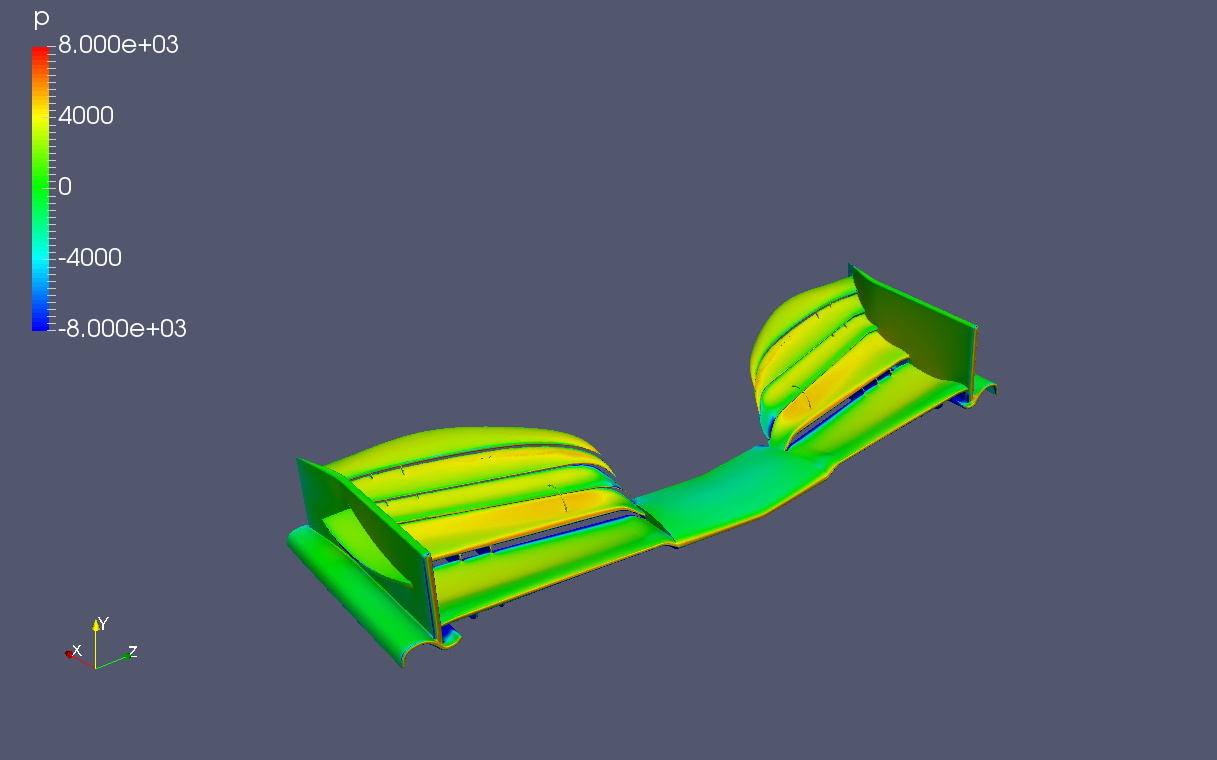
because t’s working of the wing
The wing of a car is shaped so that the air moving over the top of the wing moves slower than the air beneath it. Since the air pressure above the wing is greater than that under the wing, downforce is produced. this is the main reason why there is high velocity under the wing.
Yeah I know that and that’s why I was saying you to simulate this case as a compressible flow type problem. As the velocity is going way over 0.3 mach number it is more appropriate to perform this simulation as a compressible one(you are treating it as incompressible type problem)
Hope it would make some sense to you. If you have any issue plz clarify