Mach number is based on the local speed of sound and velocity no? Can you confirm the calculation that the mach no is above 0.3?
You do bring up a good point, but I would still say compressible flow simulations are notoriously annoying to get right and the result differences for flow that is less than 0.5 mach is not significant enough to warrant the extra complexity in dealing with compressible flow. You would usually only need that kind of accuracy if you validating a solver against a benchmark. So do consider the trade offs vs the possible increased accuracy. @ROHIT_SR
Thanks @Retsam for pointing that out. Yes, it should be disabled. Try that first @ROHIT_SR before setting a ramping inlet. Retsam also correctly pointed out that the flow progression should be linear. There was a user facing this issue and it was mentioned that if you set the differences in values for velocity too high, the solver will interpolate these values and dramatically increase the flow velocity in a way that defeats the purpose of using a ramping inlet in the first place. Again, try this only after you have attempted a run with potentialfoam disabled.
Hi @Get_Barried the mach no= speed of fluid/ speed of sound in that fluid. The speed of sound in air can be considered to be 340(will not change much even if it’s dependent on air temp) and the maximum fluid velocity is 200(although the above image was created with a velocity range from 0-200 and the max velocity is more than 200…)
Mach no. = 200/340 = 0.6
Yeah totally agree with your point that it will not make that much difference rather instead of giving a better stability to the solution, will increase the complexity of the problem.
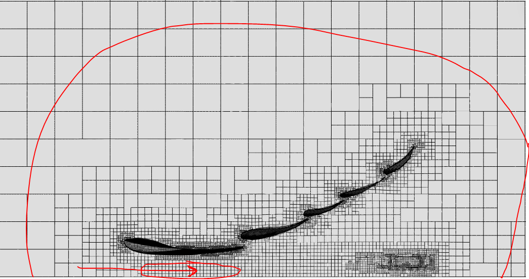
in this above image you can see the velocity under the wing are approx. 162 m/s (still its very high velocity)
can this happen in real life? @Retsam@Get_Barried@anirudh2821998
any suggestion are welcome.
but this will give some realistic results then previews one.
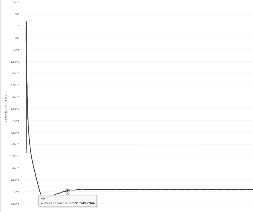
I don’t think that the results are correct. A front wing usually produces a ground force of about twice the weight of the entire car(approx 2000N) which accounts for around 20-25% of the total downforce. But here your front wind is producing a downforce of aroud 7KN(which in actual F1 cars are produced due to the combination all the components like front, rear wing, diffuser etc…etc…) I think that you should refine the mesh around your wing. Your mesh transition is not smooth as it is going from an element of 10cm to 1mm over a distance of just 10cm
I told you not to use the mesh created by me for this simulation. There are several errors in mesh that need to be dealt with before starting the simulation. I told you to take a reference from my mesh to get an idea of the mesh transition that is required to solve this problem.
The problem with this mesh are-
1.Illegal triangles were found after surface tesselation. There could be a problem with the CAD geometry. Trying to proceed anyway.
The tesselated surface is not closed. There could be a problem with the CAD geometry (such as self-intersections). Please inspect your geometry. Trying to proceed anyway
This error must be removed before you start any simulation(already told you how that is to be done)
The solver has made elements inside the front wing which is totally wrong.
Thus, I told you to just take some idea on how you have to mesh this problem and not to use this mesh.
hi @anirudh2821998
I remembered this thing don’t worry
i want to just check that can this will give accurate results or not? (trying to save some core hours ) that why i simulated this project.
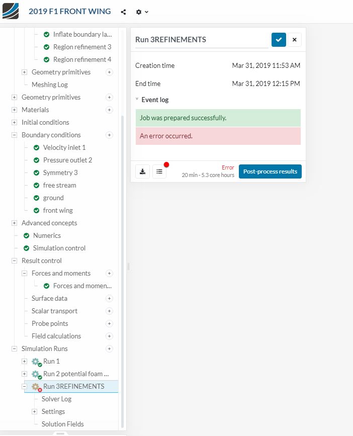
but why this will not give any results? fail in run 3 (same part give results in the previous RUN )
because I was changed only refinements level @jousefm sir can you help me?
The reason is that in my mesh the solver has made elements inside the wing and you have defined the surface of the wing as wall. Also, the mesh used in the previous 2 runs is different from mine but contains this same error-
Previous 2 runs were successful because they didn’t have elements inside the wing and the B.C assigned(wall) to front wing was correct.