This model keeps diverging and I am not sure what “pressure gauge field started diverging means”. I have used similar models to this and at the coordinates specified from the error message my model was exactly the same. Any help would be great thanks!
To anyone official people on here how do I report someone because the person above is spamming random links
Hi @ccosta23,
As the error message says, it means diverging at this position (0.005085 m, -1.904 m, 0.1367 m), which is commonly related to mesh issues. To know how to fix it, please take a look at this page.
Another advice would be using rotating walls boundary condition for the wheels, instead of using an advanced concept. In this case those rotating cylinders would be excluded, and the mesh would be better due to the thinner space between them and the wheels. Please read letter f.
best,
So I did a new simulation and I fixed what the original problem was in the cad however this time it diverged again at (0.700587491015, 0.717628742657, 0.767478515794). Yet this is just a point between two surfaces and I ran a similar model in a different simulation and I have not changed anything in that place. It makes no sense why it would diverge there because there are no sharp angles, no overlapping faces or anything else (to my knowledge) that usual creates diversions. Any help would be much appreciated.
So I found out what the issue is there is a very small sliver face that is vertical between the two part. However, even though I have the small feature suppression on to .001 of a meter it does not ignore it. I also measured the face in CAD and its total area does not even come out to .001 of a meter so I am very confused as to why this face is not ignored.
The only difference between my two models was the one that diverged had a fineness of 6 whereas the similar one that did not diverge had a fineness of 5. I am going to see if changing the fineness works.
Sorry for so many messages but I reran the mesh with the same exact setting as the other one and yet the sliver surfaces still show up I am not sure why they showed up on one but not the other.
Here is the other model
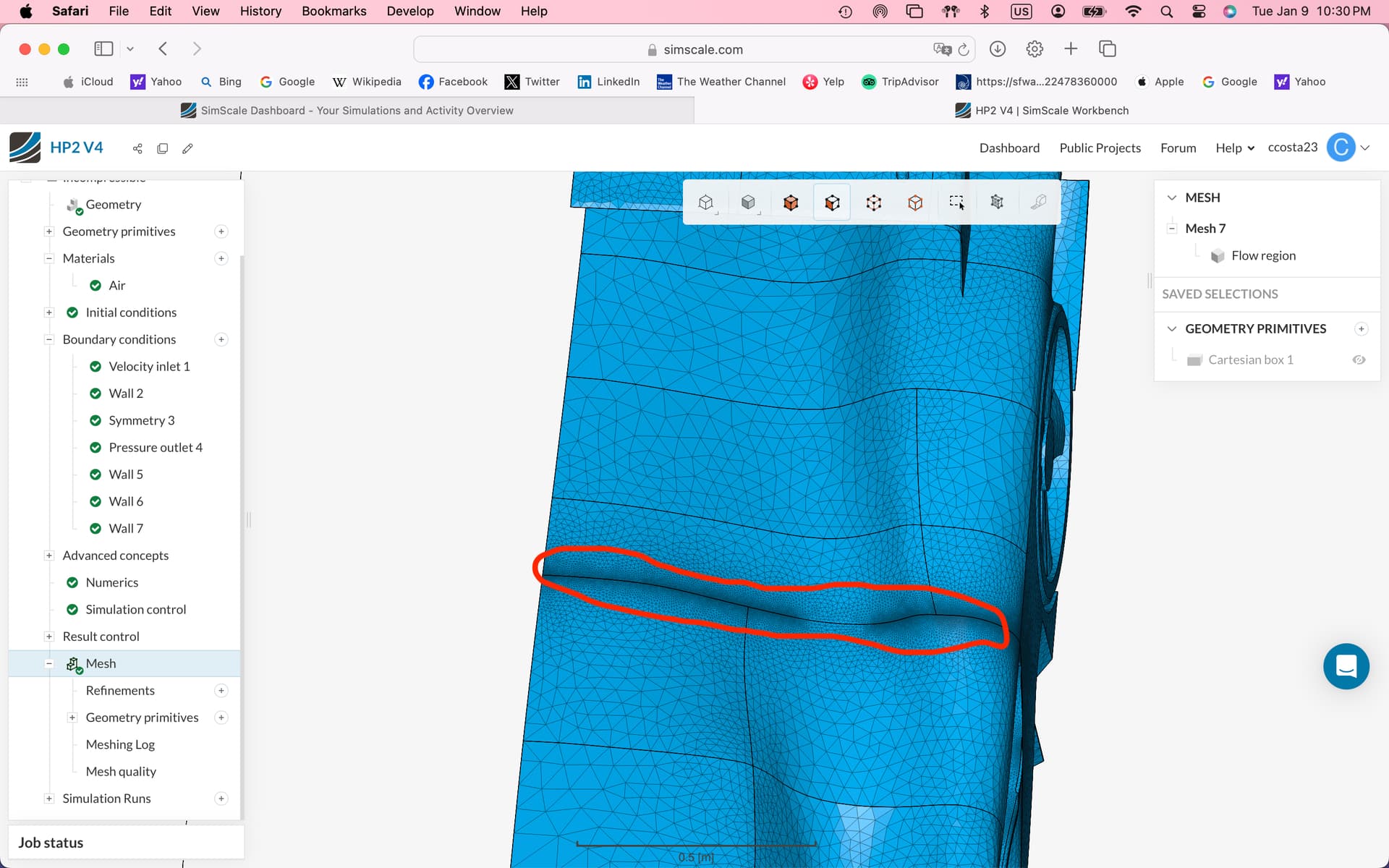
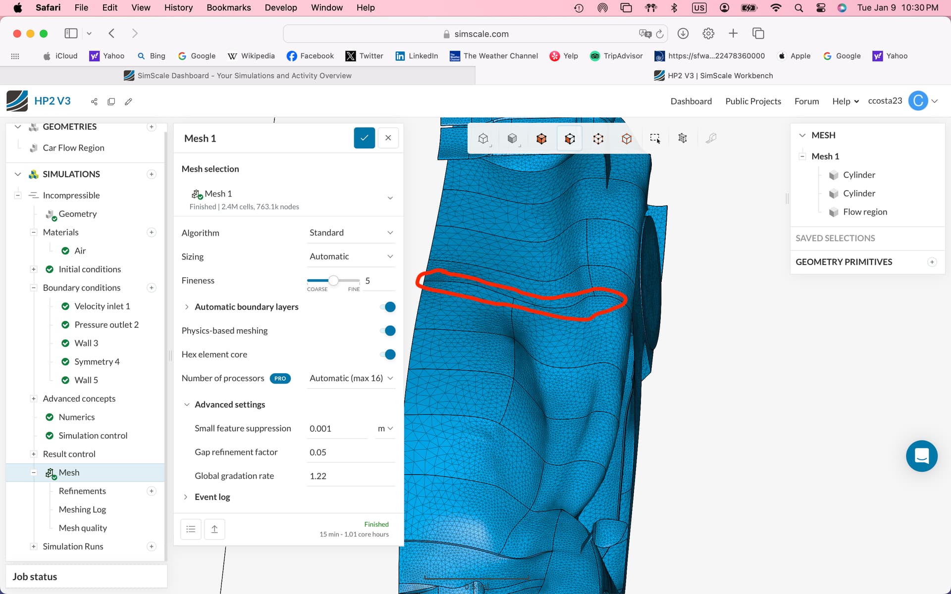
As you probably can see. Inside the red line on the model with the sliver faces the mesh becomes very small to make it around the faces but on the model without the sliver faces the mesh is similarly sized across the whole area. I also checked both models before the mesh and they both have the sliver faces. Yet for some reason in one of the simulations the sliver faces where removed but in the other simulation they where. If you could please let me know why or at least give me a clue that would be great!!!
Personally, I would get rid of those sliver faces in the CAD file and carry on.
I was able to change the small feature suppression in the mesh and that made it so that it did not diverge.