here is the project.
I had just tried the level 7 feature refinement and got the lovely floating point exception.
I didnt reduce the geometry itself, i just made the BMB box smaller. But resizing this to the correct point should do the same thing
here is the project.
I had just tried the level 7 feature refinement and got the lovely floating point exception.
I didnt reduce the geometry itself, i just made the BMB box smaller. But resizing this to the correct point should do the same thing
Looks like your L6 is just less than 0.5mm is that correct?
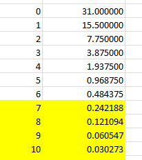
Yes here are my current levels
| Level 0 (calculated) | 0.03m |
|---|---|
| Level 1 | 0.015m |
| Level 2 | 0.0075m |
| Level 3 | 0.00375m |
| Level 4 | 0.001875m |
| Level 5 | 0.00093755m |
| Level 6 | 0.00046875m |
| Level 7 | 0.000234575m |
| Level 8 | 0.0001171875m |
| Level 9 | 0.00005859375 |
im considering making level 7 exactly 0.0002m so it will fit perfectly on the front face of the fins. Changing the surface refinement of the fin surface to level 6-7 made the total cells jump from 800k to 2.3million, which is too much for the whole radiator
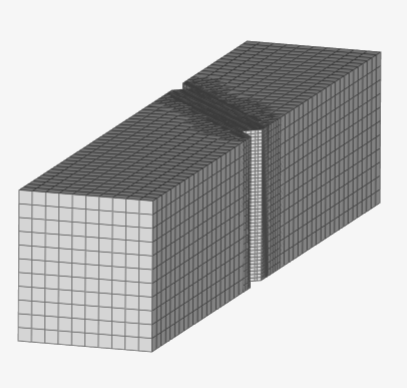
Rad Verification 23mesh cut
Rad Verification 23
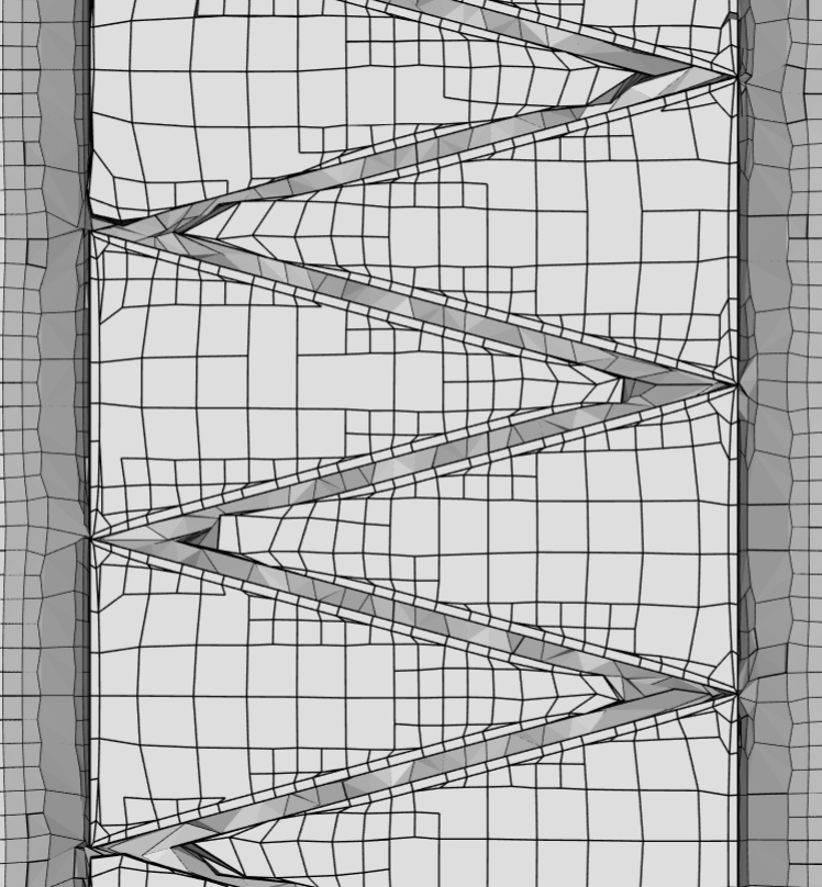
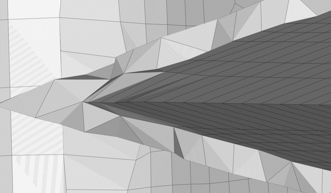
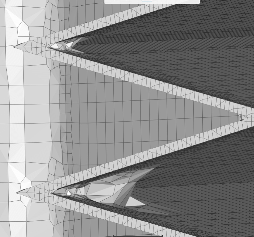
In this picture the second 30 deg fin angle is perfect. Zooming in just now i noticed someting
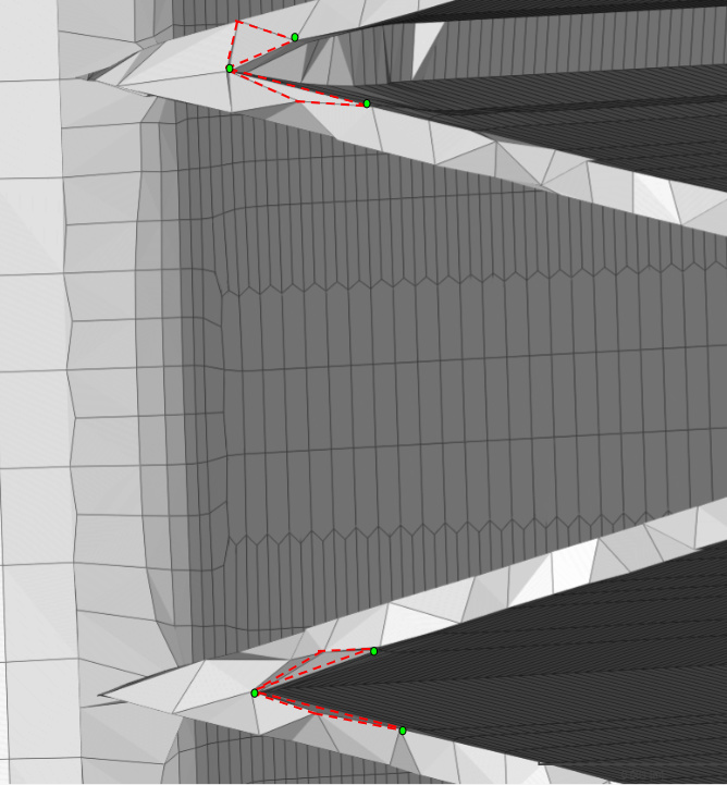
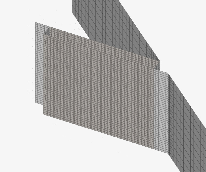
This zoomed in picture shows where the edges of the fins create cells. I have these faces at level 7 - this current cell size (0.000234575m) for this face is not what it should be because this face is 0.0002m thick. due to the cell size being larger then the geometry, we now have this… jagged, unequal sized triangles and unequal sized squares smushed to fit this face. This made me realize that the verticies created by these unequal cells might be the problem . All neon green dots are the cell nodes. The bottom fin snapped to the geometry how i want it to. It can be seen that the bottom fin meeting point has stretched cells on the small fin edge that ALLOW THE SURFACE MESH TO SNAP TO THESE POINTS.
The top fin meeting point has cell nodes that do not allow for this to happen.
Could this be the problem???
TOP
BOTTOM
I will look at that shortly.
In the mean time I redid your geometry with Level 0 at 0.031m (sorry that is what I thought you used), you will have to adjust your BMB accordingly.
Here is ref chart in mm:
That whole geometery was drawn snapped to Level 6 grid. try it out… (not much physical size differences)
Your step file opened as mm so you might need to scale that to get meters in SimScale
Origin is at a fin corner point…
It is cool that you can still have a square cube at level 0 ![]()
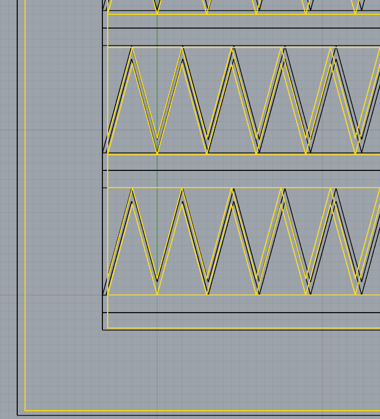
Here you see the Level 6 grid pattern with your old geometry in BLACK and the new geometry in YELLOW:
I am not sure if , by the time the blockmesh gets to level 6 everywhere, that the Level 6 cells with still be ‘ongrid’ as I hope…
Could be, also, when I redrew your geometry I did not like the interface between the rounded cross tubes and the fins.
That intersection just smells bad for meshing…
If you want a STEP file, I can give you a STEP file but I have lost my faith recently in them.
I have an open issue with them in the private PowerUser forum. (You could see that if you were a PU ![]() )
)
Also, you could much more easily see your surface mesh issues with a quick download of the mesh and in ParaView extract the surface like I showed above in my CyberTruck tread images ![]()
Use this trick to be able to view HEXpara meshes easily in ParaView ![]()
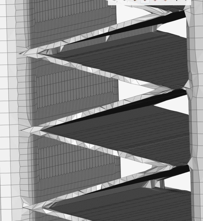
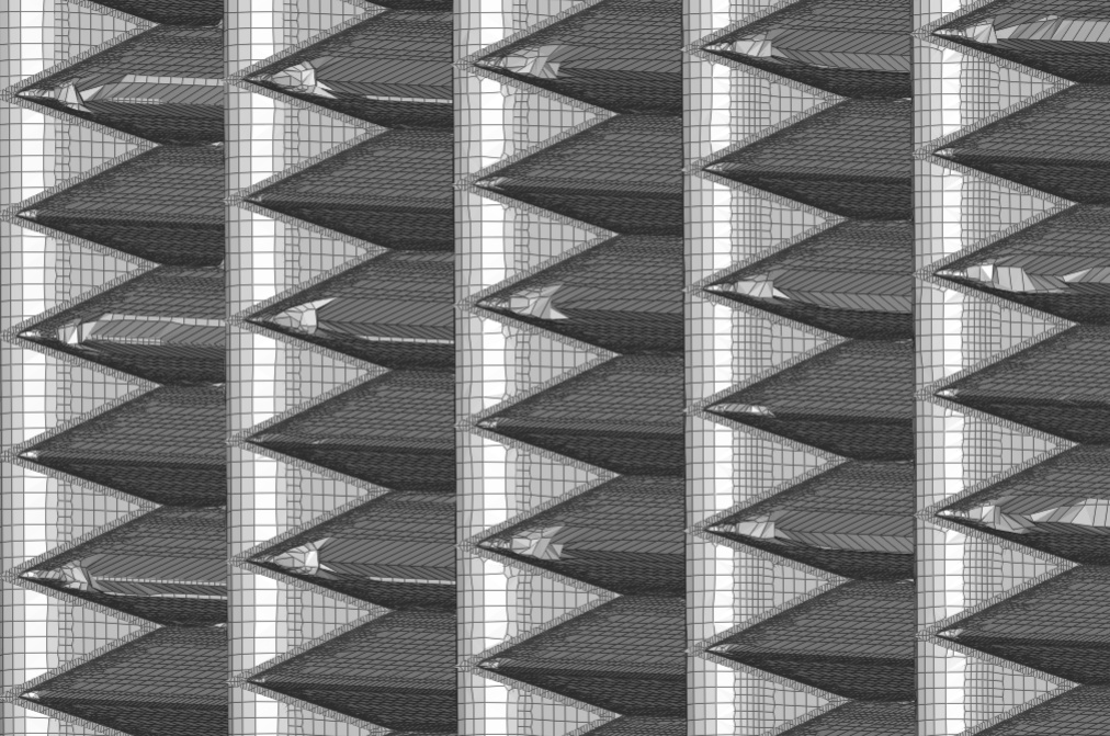
So i upped the fin edges to level 8. This helped significantly with the edge quality. However this larger view somewhat confirms my “edge between cells lining up with the geometry snap point” theory. Every other row where the fins meet has a worse snapping mesh. I think your geometry movement will help with this.
What i also find interesting is that this only seems to happen the worst as it reaches the outer edges of the fins. Not sure why on that one.
Either way Dale, i will try your geometry alignment method tomorrow, but this project in general is a “rabbit hole” for me. I really need to get back to my main goal with these simulations. However, i now feel much better equipped to resolve any snapping issues in my full car mesh.
Well, you know me by now…
I just had to proceed alone down my rabbit hole for now ![]()
I fairly easily determined that this is a GOOD rabbit hole ![]()
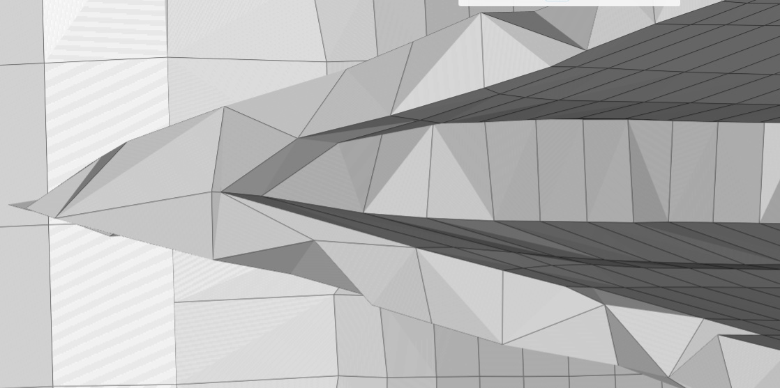
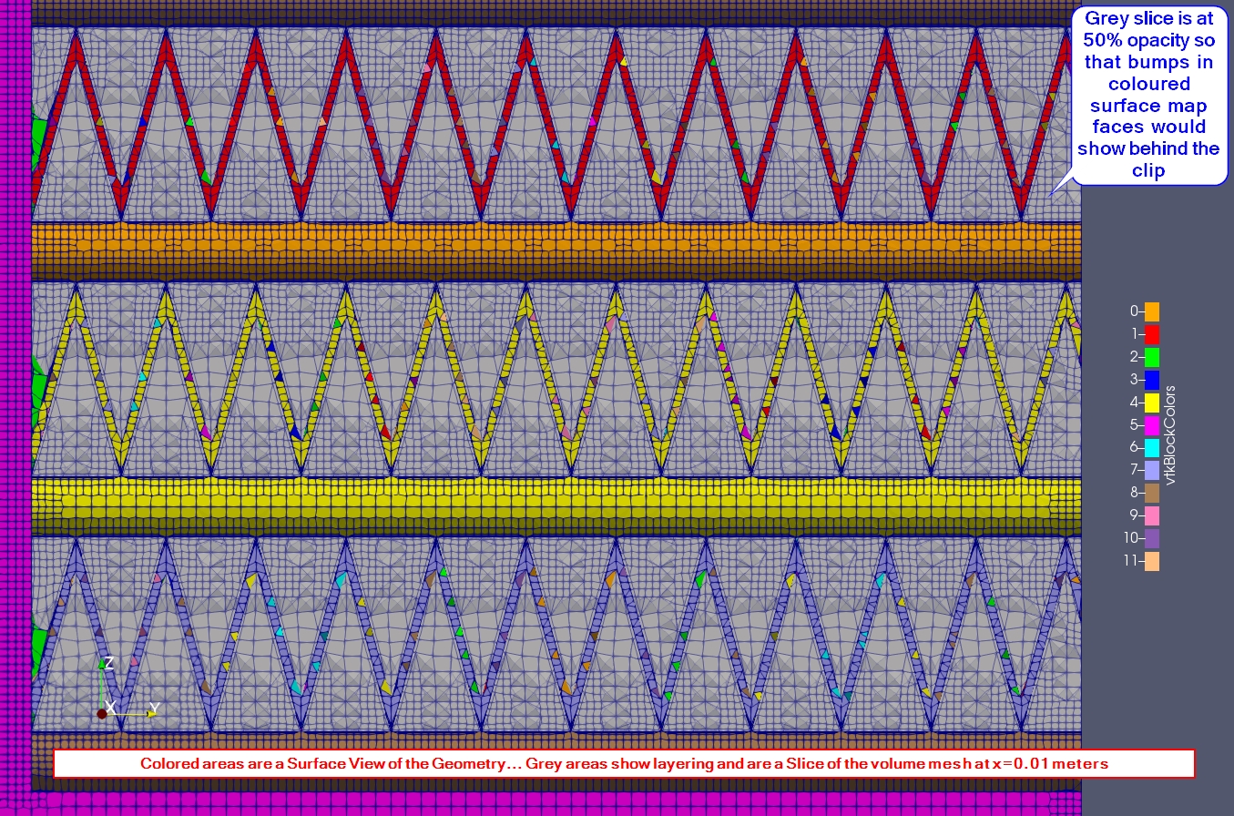
Here is a 90% layered mesh will ALL the inside corner issues resolved using a smaller CAD file section of my ‘snapped to Level 6 grid’ geometry and here is a ParaView image which shows the 90% layering in the Grey slice (at x=0.01m at 50% opacity) and it shows that all the inside corner crap is gone by looking at this parallel projection of the Colored Surface Grid:
Comments along the way:
You really should work with small geometry sections when testing out meshing on geometries like this. My small geometry only has 240 faces and this means the layer table in the meshing log snippet will be complete and let you analyze the layer %age. This one is 90% and I am sure you can improve on my quick set of 2 total refinements and default snap settings (but I did have to reduce Min Cell Volume to 1e-15) using your recent snapping experience. Using a smaller BMB does not work unless the BMB does not split a face that is layered and you select only the faces inside the BMB to have layered…
I have not tried but you should be able to capture the end of the ‘Layer addition iteration 0’ section so you can see what reason that Snappy is removing most of those 10% of layers it removes…
The only clumpy area of surface mesh cells now are the very sharp corners (left side green colored faces in above image) where the fins meet the frame. I am sure that they can be taken care of with some more effort. I would just likely bandaid this in the CAD file with a horizontal chamfer face in that sharp corner (about 0.3mm wide).
Like I said earlier you could reduce num cells further by setting ‘Cells between levels’ to a smaller number.
The leading and trailing edges of the fins are slightly jagged but likely OK for your purposes. In my geometry, the leading and trailing fin faces are 0.2549 mm wide which is only slightly larger than Level 7 distance of 0.2422 mm and which is likely the issue here.
In the long run, the abrupt and large cell volume ratio change between your single prism layer and the volume mesh cells should be investigated as to how much results accuracy is lost at this magnitude of volume ratio change.
1 layer meshing with absolute layering needs to be the subject of a sensitivity study. (unlikely to be as good of results as for wall function layering)
I think you should keep following this rabbit hole…
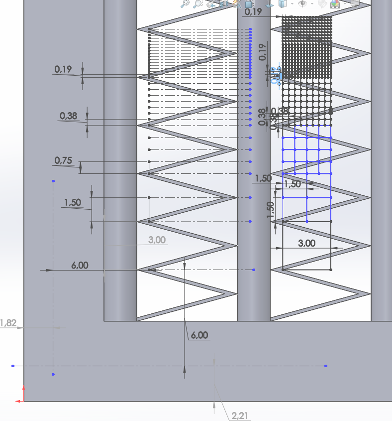
So i now have all the cell sizes measured out. The distance between where the fins meet is exactly 3mm so this is easy to work with. Calculating back we get a new level 0 cell size.
| Level 0 (calculated) | 0.024m |
|---|---|
| Level 1 | 0.012m |
| Level 2 | 0.006m |
| Level 3 | 0.003m |
| Level 4 | 0.0015m |
| Level 5 | 0.00075m |
| Level 6 | 0.000375m |
| Level 7 | 0.0001875m |
At 6mm away from the first fin meeting point is where i will put the new (0,0) origin for the bounding box. With this i can be sure that the edges of the cells meet up with the geometry as shown on the right side of the CAD picture. I mapped out the cell size for each level also.
I worry that you are just concentrating on keeping the ‘left’ problem corners ‘onthegrid’. I think that for best results, it will turn out to be important to keep all 4 (5, since I forgot the right inside corner in that image) of those key points I showed earlier ‘onthegrid’.
Yes this could be causing my current problems of floating point exception. I copied your settings exactly an i keep getting in. I also tried my previous mesh settings and refinements and it still keeps coming back
RE: Floating point exception
I am pretty sure that ‘this’ led to a conclusion that you can not use a Feature refinement and a ‘Distance’ Region refinement both in the same mesh… See if you can confirm that… sometimes mesh refinements conflict with each other and can cause floating point exceptions…
Sorry, I have not broadcast that info yet
Hmm in most of my meshes so far I had both a feature and region refinement here
I think the distinction is that ‘Inside’ Region is OK but not ‘Distance’ region…
Let me review all this before I say more, this is just memory right now there are too many things in my head right now 
I just tried the mesh again and deleted the region refinement altogether. I still have the error
I am still trying to figure out what my resolution was, but I guess my point is that floating point errors are caused for many reasons and can be as simple as conflicting mesh refinements, not just geometry/grid errors…
ah ok … super simple to mesh things huh?
I have decided to try to use cfMesh now in blueCFD, I will report if it is easier, ha…
EDIT: ‘In this case’ , neither I nor SimScale support could figure out why, when either a ‘Distance’ Region or an ‘Inside’ Region mesh refinement was added to a working set of refinements, a Floating Point Exception was encountered when meshing.
hmm i have tried a couple different runs with different refinements and still no luck.
I have another problem now on something that should be super easy. I want to see if my darcy-forchheimer coefficients are correct so that the porous media has the same pressure drop as the simulated radiator. So im doing the same radiator simulation but just with a porous media. I cannot get it to mesh, it keeps saying unexpected error. I have tried just 1 surface refinement, feature refinement and surface, surface and region, nothing works. I also tried the “Allow free standing faces” turned on and still nothing
Here is the project link. I have no idea why something so simple doesnt mesh
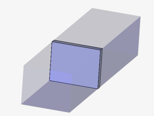
Then i wanted to do another porous media but sideways and it meshes first try
also should the porous zone be open like that? idk