that is some great advice that i always forget to do. Test on small areas then, when successful, implement quickly on the full scale. These full radiator tests are using 60-100 core hours for each mesh run and i could have worked through all these problems for a lot less. Theres always a cost to inexperience
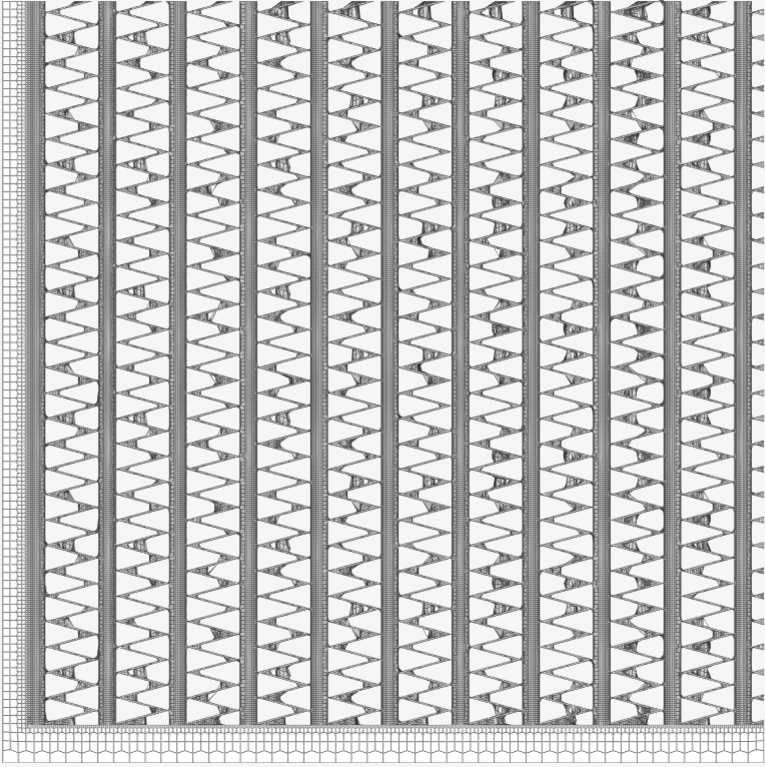
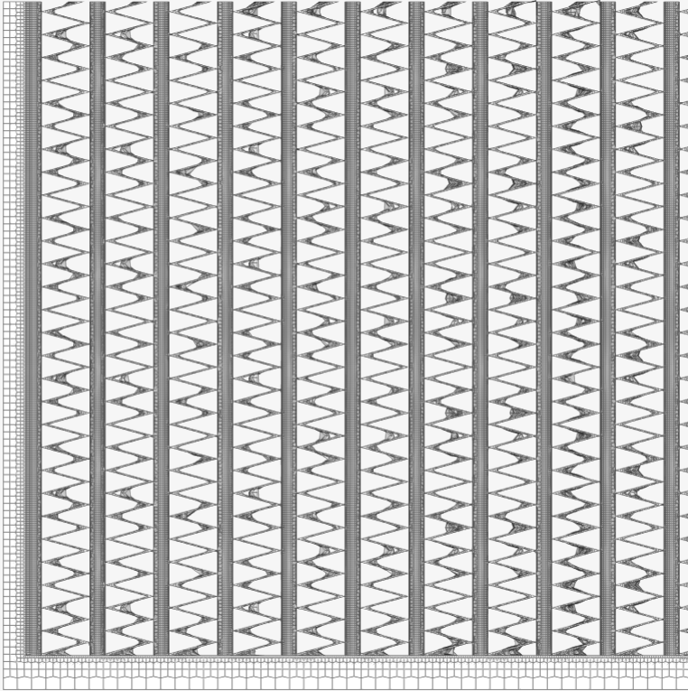
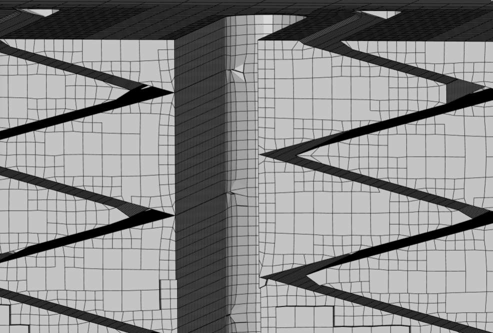
Results are in total much worse. The mesh between the fins did start a bit bigger on the flat areas and decrease in size as wanted, but at the angle where each fin meets has bridged itself worse then last time. Most of the mesh looks like this. Really bad bridging.
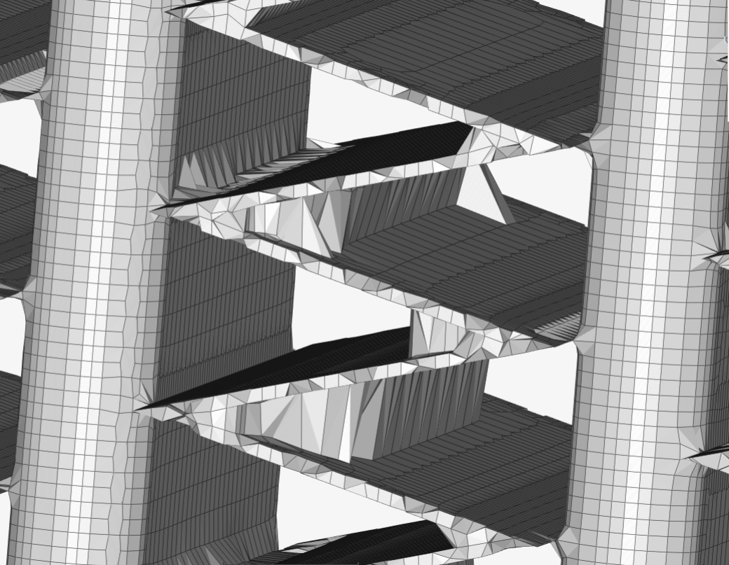
The cells did however stay at a larger size on most of the fin surface then reduce to a higher level towards the edges as desired.
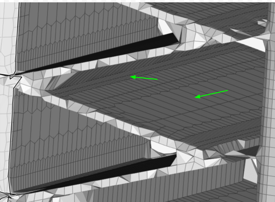
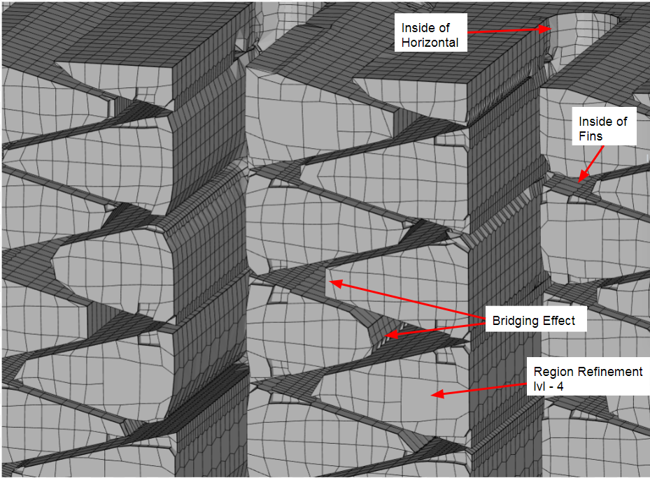
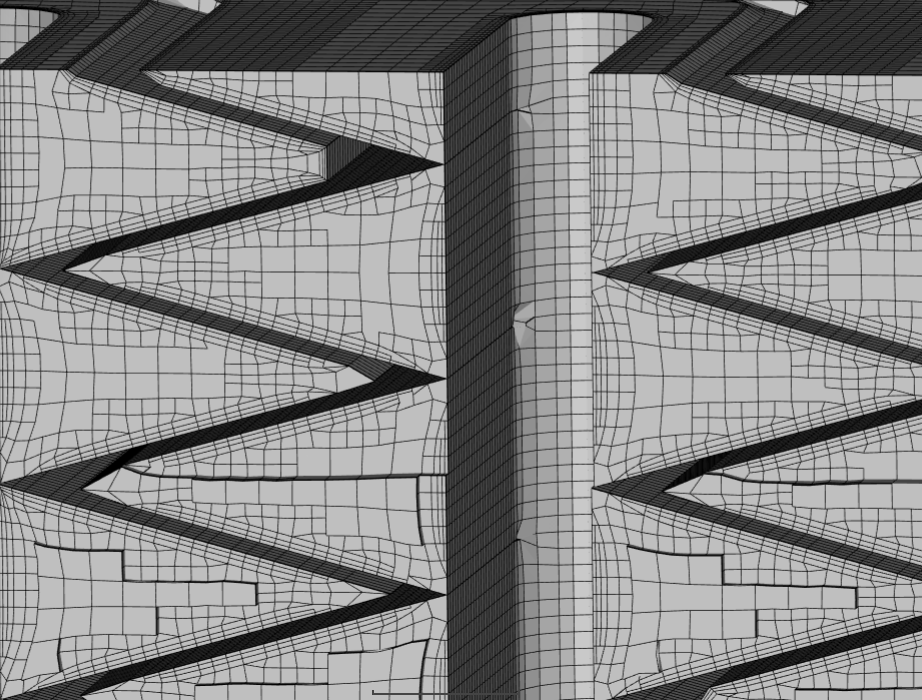
This would be an example of the optimal result. On the top green arrow shows a sharp edge between the fin and horizontal. The red triangle in the circle is the only area that bridged between the fin surfaces. This would be acceptable to me.

I am not convinced that the feature refinement is to blame. I have a theory that the problem lies within the mesh snapping controls. it could be the tolerance setting as said below
Max Relative Distance for Snap Point Search (tolerance)
This specifies the relative distance that the algorithm would search for a point to snap, the distance will be the value times the local cell length. A minimum value of 1 is required, while higher values lead to better snapping.
Important
For better snapping a value between 2-5 is recommended.
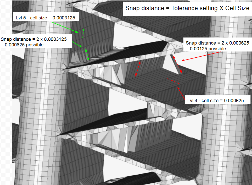
Both the implicit and explicit feature snap use the tolerance setting to search for the closest representation of the geometry. Set to 2, this allows for the mesh to snap to areas 2X the cell size. I think that I had better quality with the implicit feature snap because it is allowed to snap to a “representation” of the geometry, while the explicit MUST snap to the geometry.
I will perform another test with this setting at 1, so that it can only snap to a distance equal to the local cell size. If the results create a mesh similar to the quality in the last picture and minimal bridging occurs, then this will be suitable for simulation
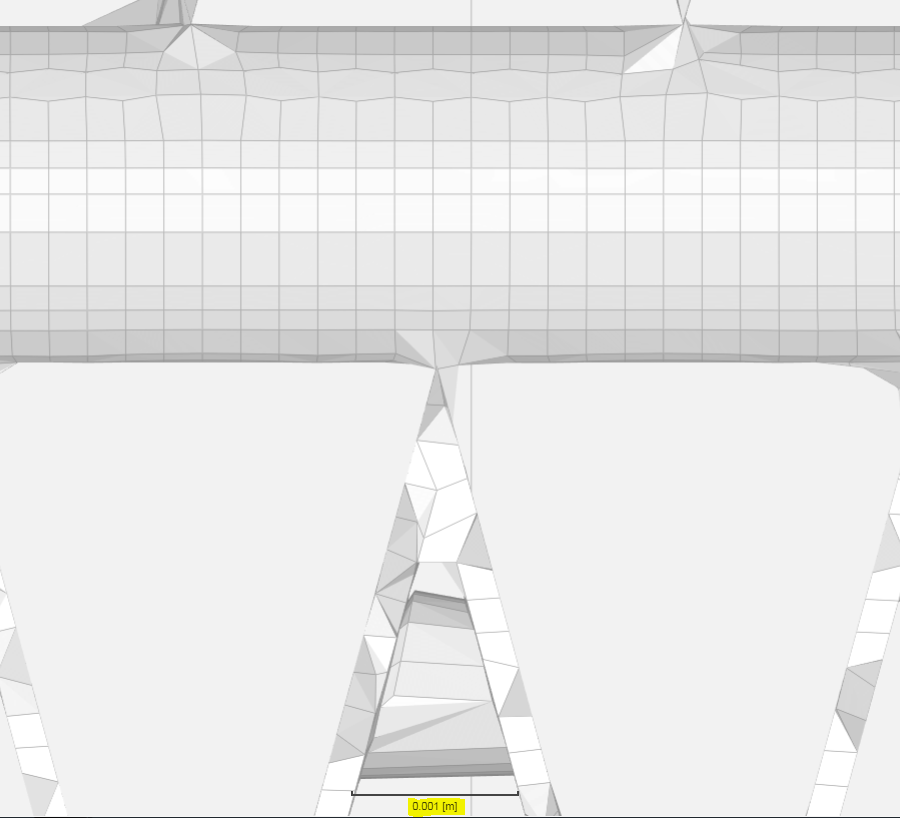
Some evidence for this can be seen by looking at the bridge sizes between the fins. The surface refinement cell size on the fin face is at level 4 = 0.000625m. The maximum bridge size is 0.001m, which would equal about 2X the cell length. In the second picture it also shows how the larger cell can bridge to farther distances due to this calculation.
I couldnt reply three consecutive times so the Raceyard account was HACKED haha
Rad Verification 7
I have used the following settings for this run and the previous run outside of the highlighted settings. Changing the tolerance to level 1 had minimal effect on the bridging. I have also done the next run with implicit snap ON again to see the difference, however it also had little effect.
| Refinement | Other Settings | Level |
|---|---|---|
| Surface Fins small faces | 7 | |
| Surface Horizontals small faces | 4-5 | |
| Surface Fins and horizontals large faces | 4 | |
| Surface Rad Housing faces | 1-2 | |
| Region refinement Wake box | Inside - Geometry Primitive | 1 |
| Fin and Horizontals region refinement | 4 | |
| Inflate Boundary Layer** | 1 Layer - Absolute | 0.00002m |
| Feature Refinement 1 | Included angle: 16 deg | lvl 7 |
| Feature Refinement 2 | Included angle: 31 deg | lvl 6 |
| Feature Refinement 3 | Included angle: 75 deg | lvl 4 |
| Feature Refinement 4 | Included angle: 91 deg | lvl 2 |
| Mesh settings | Input | |
| Cells between levels | 1 | |
| Mesh to geometry conformation iterations | 6 | |
| Solver iterations | 300 | |
| Implicit smap | OFF | |
| Explicit snap | ON | |
| Tolerance** | 1 |
Rad Verification 7
Rad Verification 8
Same settings as #7 but with implicit snap on. Comparing these two pictures it seems that the implicit snap does a bit better job at refining the features.
Rad Verification 8
Rad Verification 9
For this run I decided to turn Explicit snap back on and increase the setting “mesh to geometry conformation” to 12 as this makes the algorithm run more iterations for the nodes to snap to the existing geometry. I had hoped this would show improvement but it did not help much.
Rad Verification 9

Then I decided to do a mesh clip to see if layers were being generated and how the region mesh looked. I found that:
1st - I do not see layers being generated. This is a problem.
2nd - the level 4 region refinement could be the reason that the bridging occurs.
On previous meshes, layers were generated with 1 layer, absolute layering, at 0.00001m. This also occured with a level 6 surface and region refinement. I had hoped that, like a surface refinement reducing its levels, that the region refinement would do the same as it comes closer to the Boundary Layer. This however did not happen. The next test will have this “inside” region refinement at level 6.
Geometry Primitive - with inside level setting
Could anyone verify that my resutls are correct for this size radiator? I have the following Velocity Vs pressure loss data from the manufacturers simulation of the radiator.
| Pressure drop vs Velocity | |
|---|---|
| Velocity (m/s) | Pressure (Pa) |
| 1,012 | 23 |
| 2,024 | 61 |
| 3,036 | 108 |
| 4,048 | 164 |
| 5,061 | 230 |
| 6,073 | 303 |
| 7,085 | 385 |
| 8,097 | 475 |
| 9,109 | 573 |
| 10,121 | 679 |
This results in the following otupt for the coefficients. Are these resonable?
| Darcy | D | 72895531,88 |
|---|---|---|
| Forchheimer | F | 403,59 |
I have also updated the first post again with how to determine e1 and e3.
Please check my work!
Sorry, I have not followed that part of this topic.
But I just want to point out the fact that SimScale is currently using OpenFoam v1606+ released 30/06/2016.
The descriptions of the Snap controls for that version can be found here in the UserGuide for v1606+.
Be careful since newer versions seem to have different Snap parameters available (which I wish we had access to ![]() )
)
Thanks a lot Dale! I read through how this all works again. Its helpful to go back to the basics as it gives me new ideas on how to make the mesh work better. I still think that if i knew these settings better it would help. there arent very in depth descriptions of what each setting does (Castellated mesh, snapping, layer addition) or maybe i just havent found it yet. Either way I think im making progress slowly.
I was able to see decently sharp edges with run 13. Level 7 - 0.000234m cells near the edges worked well but layers were not created on this run.
Run 13
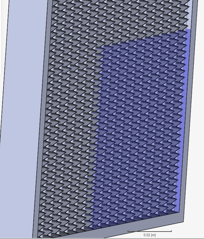
Then next run worked out well. 3 Layer BL with good expansion ratio and final thickness ratio. However a 3 layer BL with level 7 cell make for a huge mesh at 5.1 million cells. These last few tests have been done only in a region only about 1/6th the size of the whole radiator so i need to have these meshes around 1-2 million cells for them to be applicable to the whole radiator.
Run 14
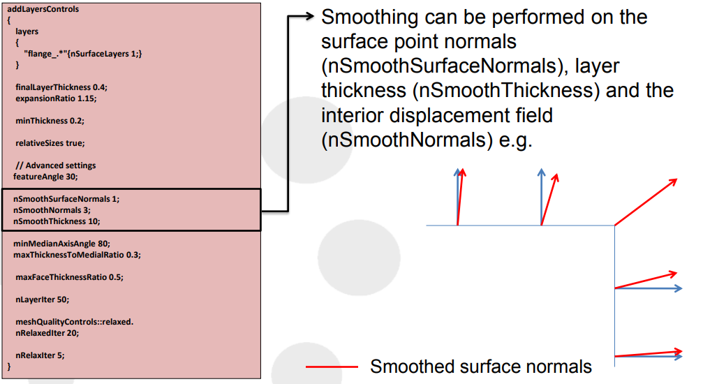
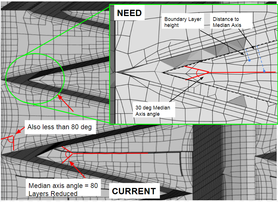
Since run 14 had decently sharp edges at the fins, the quality is acceptable, however i wish to get better layering, and most importantly reduce total cell count. The following settings are interesting as they effect how the layering is done. minMediaAxisAngle is a bit confusing. There is simply not much info on this.
Max Face Aspect Ratio for Layers (maxFaceThicknessRatio)
This specifies the maximum allowable value of aspect ratio. Sometimes (especially in corners) the layers must be generated over highly warped cells. The layer generation will stop for cells where aspect ratio is higher than this value.
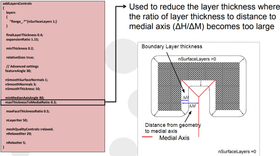
Max Ratio of Layer Thickness to Medial Length (maxThicknessToMedialRatio)
This specifies the maximum ratio of thickness to medial distance. Layer growth is reduced where the ratio is larger than specified value.
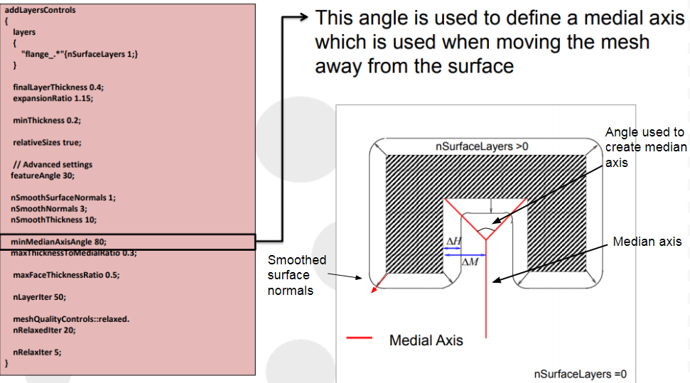
Strictness for measuring Medial Length (minMedianAxisAngle) [°]
This specifies the Angle used to pick up medial axis points.
Looks better, Run 14 is significantly your best so far 
Since you sent me some OpenFOAM documentation, i decided to look a little deeper for some better info and found THIS
It gives me exactly what im looking for, better descriptions of snap controls and quality controls. Specifically the following;
This is my goal for this next mesh. I need to somehow stop layer reduction from happening. I believe it has to do with the median axis angle and median axis ratio.
Also found more good things in this Tutorial
As well as this description Here
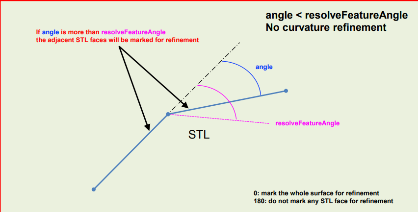
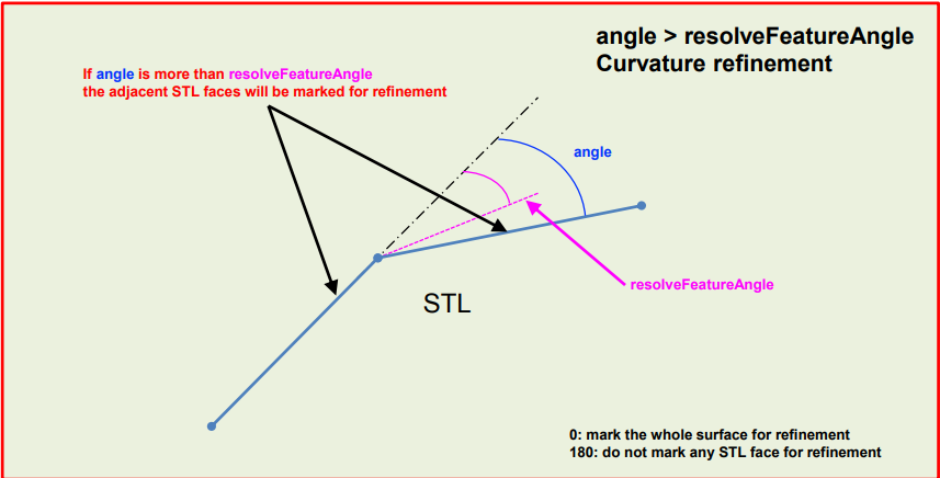
Since the edge of the cylinder = 90 deg, a resolve feature angle of 60 marks this edge for refinement. Whats interesting is that this helps me confirm what exaclty Explicit feature snapping does.
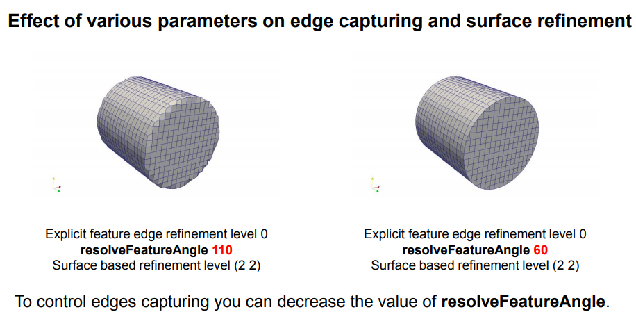
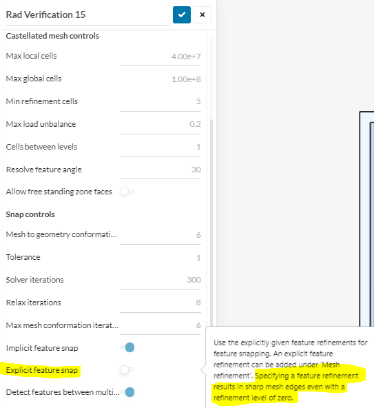
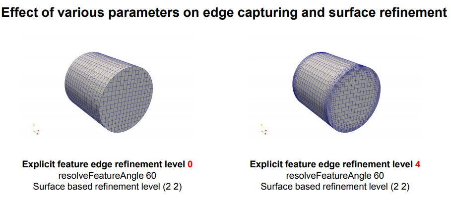
With the explicit feature snap. We can specify edges to be sharp without having to increase the cell refinement size to do so. By setting the refinement level to 0 with Explicit snapping, we get sharp edges without the extra cells added from an increased level refinement.
However we can easily increase the refinement level if we want.
.
.
.
Switching back to a 1 layer BL, still in absolute mode produced good coverage in the larger angle areas. However the area between the fins (30.45deg) are still being reduced. With my new understaning of Explicit feature snapping i will now try again with this set to true and a feature refinement level of 0.
Very well done on the research!
In the meantime, I have discovered the issue with my CyberTruck tread ‘bumps’, where Snappy will not snap to the tread all over the tire. Here is what was happening, here are the unwanted bumps (CAD file with 5mm clearance MRF):
And here is the bump free surface after I isolated the issue (CAD file with no MRF):
The issue is in the way that Snappy begins with meshing using Blockmesh and then snapping those regular shaped block cell vertices onto the surface nearest the vertex (or a rule like that). In my case, I have an MRF cell zone that has 5mm clearance to the tire tread. At some points around the tire, Snappy just snaps the vertices to the MRF surface instead of the real geometry surface ![]()
I have not found a solution to that issue yet because I can not remove the MRFs in the mesh in order to get rid of the bumps (I just made a CAD without the MRFs so that I could prove the theory of why I had bumps, which took many hours to come up with).
BUT, it does apply to you somewhat because I think your mesh is being filled in the tight corners for a similar reason. Snappy may be just moving those block vertices to the nearest geometry surface, which in a lot of your cases is the wrong geometry surface to snap to and results in those filled in fillets. Just another rabbit hole to investigate…
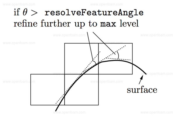
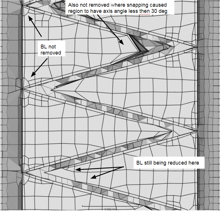
Here is my current theory on what is happening. And it has to do with tolerance, explicit or implicit snapping, mesh to geometry conformation, and relaxation iterations. During the castellated mesh step, the selected refinements of cell size are created as shown below. Red cells are outside of the geometry, blue are inside of the geometry. I currently am using an equal min max refinement of 6 for the fin faces. Therefore, any cells above my preset resolve feature angle of 15 deg stay the same level. The fin angle is currently at 30 deg, so if i switch to a unequal min max of 6-7 on fin faces it will refine the areas close to this angle.
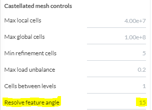
The minimum level is applied generally across the surface; the maximum level is applied to cells that can see intersections that form an angle in excess of that specified by resolveFeatureAngle.
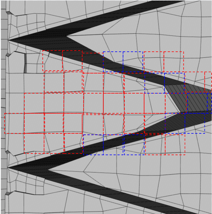
Any cells inside the geometry are deleted and the castellation step is finished. All remaining red cells are left as the rough structure of the geometry.
Cells are retained if, approximately speaking, 50% or more of their volume lies within the region.
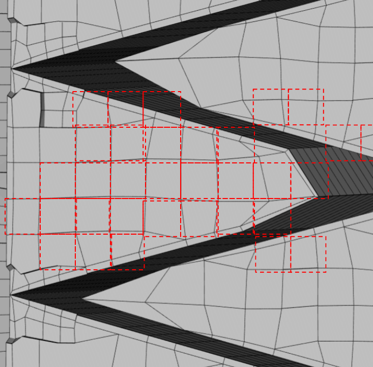
This is when the snapping iterations start. Any cells that are intersecting the geometry or have gaps to the geometric face are “snapped” to the face. This is done by the algorithm searching for a geometric point to snap to by multiplying the largest edge length by the user input amount of Tolerance.
Tolerance
Ratio of distance for points to be attracted by surface feature point or edge, to local maximum edge length
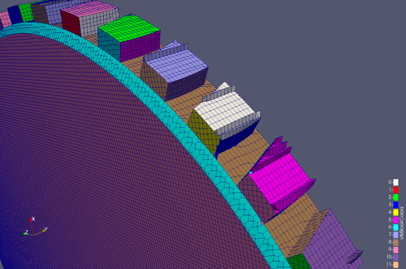
In my case it can be seen that the box question is the yellow colored cell. When snapping, this cell must scan the geometry to find a point on the geometry for the vertices to attach to.The number of times the algorithm attempts to find this point is given by mesh to geometry conformation iterations. The steps for this are shown on the OpenFOAM guide below.
The next stage of the meshing process involves moving cell vertex points onto surface geometry to remove the jagged castellated surface from the mesh. The process is:
- displace the vertices in the castellated boundary onto the STL surface;
- solve for relaxation of the internal mesh with the latest displaced boundary vertices;
- find the vertices that cause mesh quality parameters to be violated;
- reduce the displacement of those vertices from their initial value (at 1) and repeat from 2 until mesh quality is satisfied.
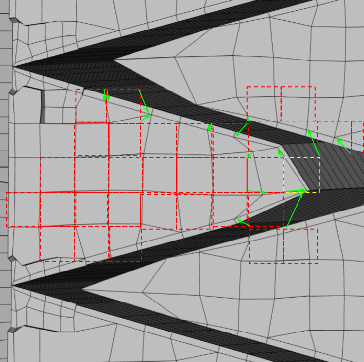
I have three theories why this section did not snap correctly while the fin area directly below it did.
- During the castellated meshing step, this yellow cell was removed and therefore, the tolerance input was not high enough for the algorithm to search for the geometry edge to snap to where the fins meet.
- The yellow cell was not deleted but, as in #1 tolerance was too low.
- Another possibility is the uncontrollable cell location from the castellated meshing step. The edges in between the cells happened to land in a bad spot causing the cell to potentially snap to a spot that is deemed bad in the quality checks. This will tell the algorithm to try another spot to snap to.
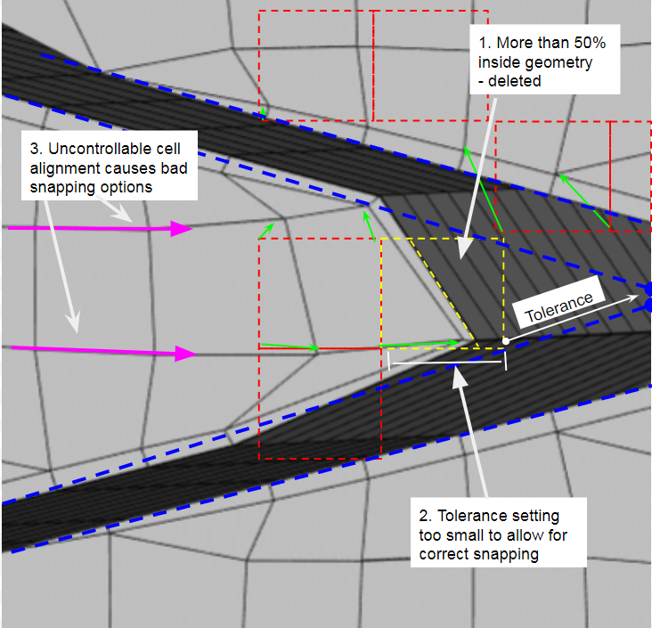
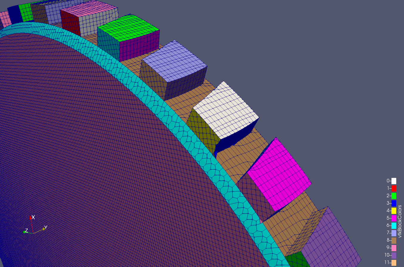
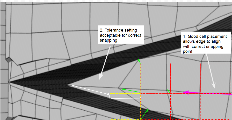
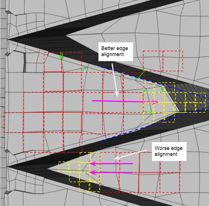
Were the fins connect just below this example, the cells snap to the correct location on the geometry. I think the more likely cause of this is that the cells edge aligns with the geometrically correct snapping point, allowing for cell vertices to easily find this correct point.
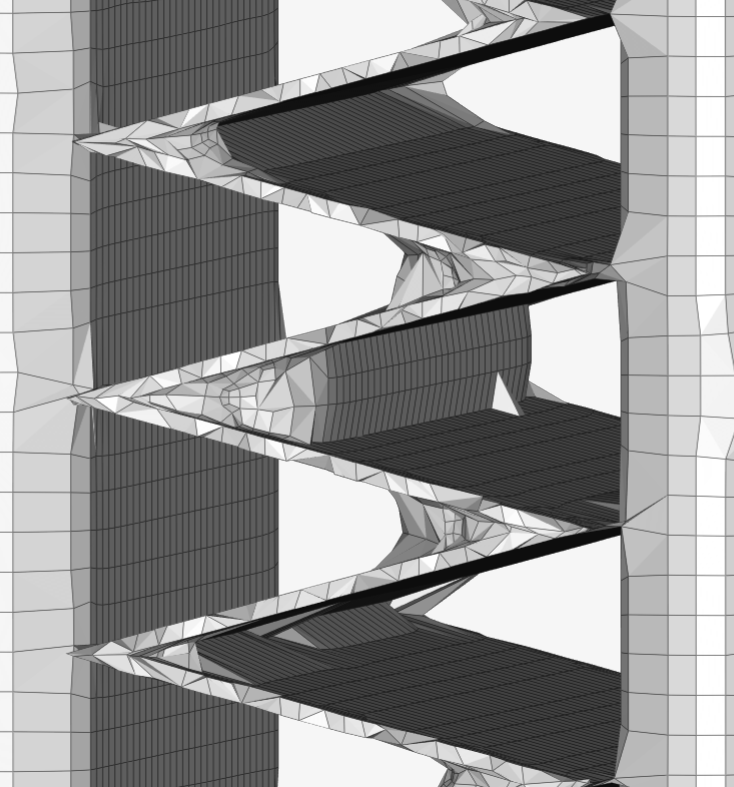
Here is a run with;
Implicit feature snapping
Tolerance - 0.75
Surface refinement level equal at level 6
Feature refinement - distance 0 - level 0
Region refinement - distance 0.0002 level 6 - distance 0.0005 level 5
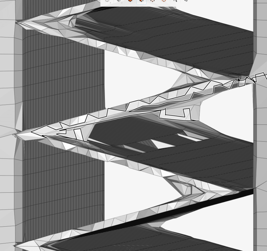
And here is a run with the exact same settings just tolerance at 4. With this setting I am getting cells snapping to the wrong side of the fin geometry. Most likely because it is allowed search so far for a point to snap to.
Conclusions:
It seems necessary to have a higher feature refinement level where the fins meet. This angle is too small for deleted cells at level 6 to snap that far correctly. Also problems of the cell edge not lining up to the snap point should be resolved because the level 6 cells will split into half, creating the edge at the proper location. However, this will also half the previously correctly aligned level 6 cell to a worse condition. I can only hope the smaller cells can conform well enough to not cause more problems. A final downside is with level 7 cells being created, the total cell count will go up significantly.
Very nice progress report.
It let me visualize another rabbit hole to look into.
Perhaps, we need to ‘live with the beast’ instead of modifying its behaviour too much 
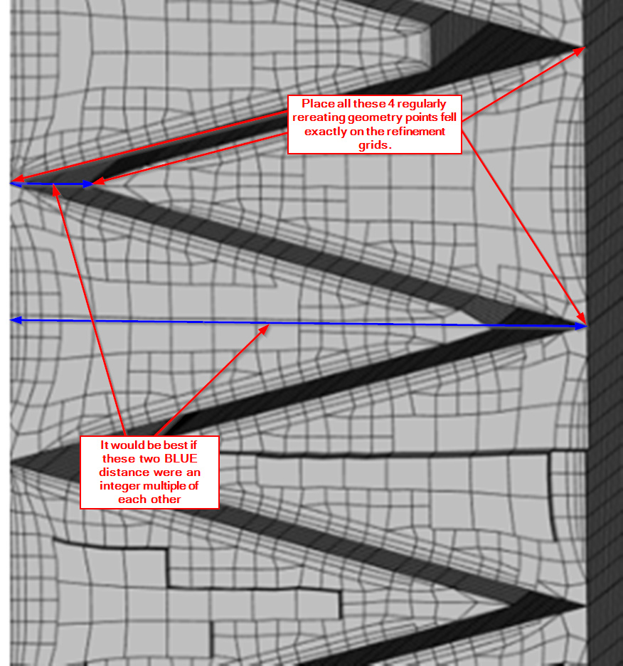
In this case of yours, since you have such a regularly repeating fin structure, how about forcing Snappy to see each fin problem corner exactly the same wrt to the blockmesh corner vertexes. In that way, once you have one corner that meshes nicely, you have them ALL 
This may mean ‘non square’ cell faces in the level 0 grid and to align the problem ‘corner’ vertices to ALL fall on the grid corners of a certain refinement level etc…
Thats a good idea! purposely changing the BMB so that the cells are not square. This method might also help with my theory of needing level 7 where the fins meet at such a small angle. If mesh can snap to these areas easily, then only level 6 will be required saving a lot of cells
Thanks!
Here is thought on that:
And since all good meshing begins with the CAD file, I would suggest putting ONE of the fin points at the 0 origin in that CAD file ![]() (this will make sure the Level 0 origin is at one of your key points…)
(this will make sure the Level 0 origin is at one of your key points…)
Also, the next column of fins would have to put their 4 key points on the ‘x’ (in these images) coordinates of the block mesh vertexes over there. Maybe need slight modification of column spacing (and fin design) to do all this…
Guess i got some CAD and Calculations to do haha. Thats a good idea, lets see if it works out
Some rabbit holes are deeper than others (but it is an easy geometry to try this on )
Maybe set up a grid in CAD to the X and Y spacing of the Level 6 (or 7 or maybe even 8… ) that you want the grid spacing to be in the inside corner and turn on ‘snap to grid’ and then redraw the whole geometry…
I think errors introduced because you may have a geometry CAD file that does not exactly match your real world geometry could be much less than the errors introduced with crappy meshing in the corners of an exact real world CAD file.
Yea i dont want to get too deep into this. I have spent more time then i should have on it already. Although i have learned a lot in the process.
My plan would be to align everything to level 6 because any higher and i will run out of memory.
Give me a link to your reduced size geometry, I can give you a revised CAD file to try pretty quick…
If you use feature refinement to L7 to a distance of <L7, then the L7 cells should only be at feature edges and not increase num cells much, also, perhaps lower the ‘cells per refinement level’ too in order to lessen the num cells increase…