Porous Media Simulation Guide For FSAE Radiator

If you take -100 Pa for the outlet pressure, your porous zone pressure drop will be too big (read the post above).
I’ll go back to my case since I used water and, therefore, delta P is more pronounced: I took 20 Pa for the downstream pressure instead of -3000 Pa.
Had I taken -3000 Pa, my porous zone would have given me a permanent, non recoverable pressure drop of about 3000 Pa more than the real geometry.

The key difference here is:

  • for the real geometry: there’s an increase in pressure downstream from the porous zone;
  • for porous zone: there’s no pressure recovery.

Ah ok i think i misunderstood you then. So i should be taking the values after the recovery, and in my first Picture this would be the light green region at -3Pa.

This would then give me

  • Pre- radiator pressure of 100Pa
  • Post - radiator pressure of -3Pa

So a Pressure drop of 103Pa

1 Like

So doing the same thing for the velocity, which according to the video should be measured at the radiator face. We can see that the air is starting to speed up as it get closer to the radiator face so it can fit through the fins. For this my inlet velocity will be 11m/s over the set wind tunnel velocity of 10m/s

I have updated my first"Guide" post to include instructions on how to make the curve fit from Pressure VS Velocity data, as well as shown which data to collect from a simulated radiator.

Please scrutinize this first post so that there are no errors!

Thanks

1 Like

From that example in the first post, my excel file results in the same polynomial approximation formula and forchheimer coefficient as yours. The Darcy coefficient formula is inverted: it’s d = A/(mu*T), which results in 12 685 122.53

1 Like

Thanks for the check! I have updated the post. When i eventually get my Radiator simulations done i will upload my data and have a final data set for the post

I have just completed the second test to achieve a suitable Y+ < 8 and the results are not much better. The first run from before was using a 1 layer BL with absolute layering at 0.0000153m cell size. The second test has the same conditions but now at 0.00001m cell size. Since the results were about the same, I am considering switching to relative layering and reducing the cell size to 0.0000075m. Any thoughts? I think another problem is possibly that layers are not being generated. The geometry has many sharp faces and the overall mesh to geometry quality has been sub-par.

1 layer BL with absolute layering at 0.00001m cell size

Stability to 1% was also found at about 500 iterations

I will have a look, but not until after I finish and submit my SimWing Challenge Project whose entry deadline is today :wink:

Can I have a direct link to that Sim Run :question:

Your doing a challenge Project? that pretty cool, good luck! No rush on checking my work, i have to learn by trial and error sometimes haha.

Here is the latest sim run. I added a feature refinement to try and get the mesh to conform better but i accidentally set the max to level 6 and not 7. Im doing another mesh run now with a 3 layer BL. Looking over my calculations this should work out with relative layering.

boundary layer settings Y+
Layers 3
1st 0.00001512 Y+ = 1
2nd 0.00001966
3rd 0.0000255
Total Thickness 0.00006028
Expansion ratio 1.3
Min thickness 0.000001m
Final layer thickness 0.4
  • Level 6 = 0.00015625 or 0.15mm
  • Smallest face is frontal radiator fin thickness at 0.0002m 0.20mm

Level 6 = 0.00015625 * 0.4 final thickness ratio = 0.0000625

Total thickness of all 3 Boundary Layers Combined = 0.00006028

Level 0 (calculated) 0.01m
Level 1 0.005m
Level 2 0.0025m
Level 3 0.00125m
Level 4 0.000625m
Level 5 0.0003125m
Level 6 0.00015625m
Level 7 0.000078125m
Level 8 0.0000390625m

I wanted to try the 1 layer approach first but now i will try the next run with a the higher feature refinement level 7 for the small areas and use relative layering for this 3 layer BL. Ill post the results

Yep, my first thought was that 1 layer would not be relevant for full resolution meshing but I want to have a look anyway…

Yea i think my problem is more mesh conformation, that the layers are not forming correctly. Hopefully the feature refinement and relative layering will be better at this. It should only take about an hour or so to finish

Sooo that mesh failed. Problem states that it ran out of memory. I guess adding one higher level for the feature refinement and 3 layer BL was too much. My previous two successful meshes had 3.9 million cells. Im surprised that this would cause such an increase. Looking back at the previous meshes I wanted to look at the layer formation in the meshing log. I know only faces selected for a BL refinement get layers so when i see these zeros in the log i know why. but in the following log, when i scroll to the top, all faces have 0. Im not sure if i cant see the beginning of this log (because there are so many faces for a radiator) or if they actually all have 0 and no layers are created. I looked through the forum on how to download a full meshing log but couldnt find anything.

Be careful, those 0’s could also be for faces that you selected to have a BL created for that lie outside the BMB (like for instance, inadvertently selecting faces that are on the other half of a symmetrical geometry).

ah yes i forgot to mention this too. I noticed this on my half car simulations where i didnt want to select every face that was within the BMB so i just selected all of them for the BL refinement. Anyway i can confirm that layers were even created on these surfaces? any way to get the full mesh log?

I feel like the log is just too long and it cuts off the results after this limit. I can go into the solutions field and with the mesh clip physically look for the BL but it would be nice to see the percentage of faces that have layers. then i can determine if my mesh is bad or if the wrong BL cell height is to blame for the erratic Y+ range coming from the histogram

Only by watching it and capturing the window to the clipboard each time it changes, but I don’t think even that will work for a long layering table (just too fast it goes by).

This is a big bugaboo of mine, in that SimScale won’t save the whole log, it can’t be because of storage space since even the full log is measured in kB, when each solution set of as sim run take GB… ;(

Yep, I finished it yesterday.

You might find some of the ParaView tricks I describe useful.

Here is a link to my project where you can find those tips.

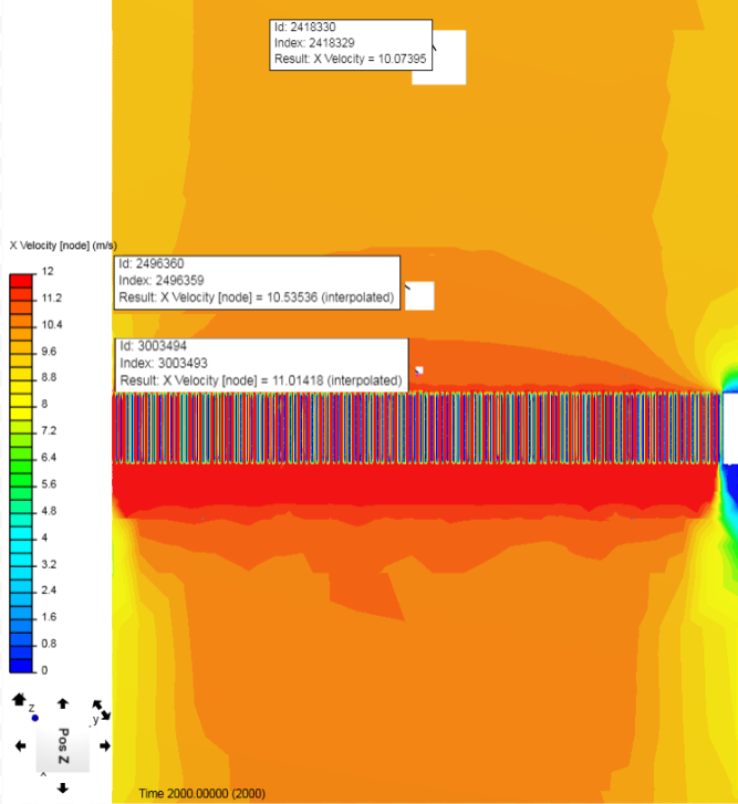
So after many failed attempts to improve mesh quality. I am trying a new strategy. In the previous meshes I was trying to use a feature refinement to decrease the cell size where the fins meet. I had the problem of the mesh connecting the fins where it shouldn’t as shown below.

After the 5th failed attempt, I copied the meshing log as it appeared and recorded the cell sizes after each iteration. (way to many cells, memory issues) Part of the problem is that I had some of the mesh quality settings too high I think, with the belief that it would help with the mesh conformation to the geometry.

  • Min refinement cells - 4
  • Mesh to geometry conformation iterations - 13
  • Implicit feature snap - ON
  • Explicit feature snap - OFF
Iteration Type Number of cells
Feature Refinement Iteration 1 3810
Feature Refinement Iteration 2 14730
Feature Refinement Iteration 3 92500
Feature Refinement Iteration 4 403314
Feature Refinement Iteration 5 1515012
Feature Refinement Iteration 6 5117296
Surface Refinement Iteration 0 6932452
Surface Refinement Iteration 1 7117091
Shell Refinement Iteration 0 15545988
Shell Refinement Iteration 1 20989202
Shell Refinement Iteration 2 21135957
Shell Refinement Iteration 3 About the same
Shell Refinement Iteration 4 About the same
Coarse Cell Refinement 0 21167128
Interface Cell Refinement 1 21787461
Interface Cell Refinement 2 21916590
Interface Cell Refinement 3 About the same
Interface Cell Refinement 4 About the same
Total cont before cell reduction 21916590

I think i should reduce the setting “Mesh to geometry conformation iterations” so that the refinements stop earlier and dont create/do so many checks on the cells

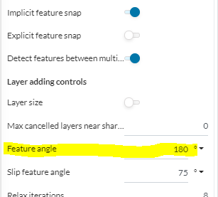
After looking at the advance control settings again in the Simscale documentation, I noticed that I have probably been making a big mistake with the feature refinements. When Implicit feature snap is - ON, but without a feature refinement being created, Implicit feature will estimate the geometry and automatically snap to calculated point on the geometry.

Implicitly Detect Features for Snapping (implicit Feature Snap)

The implicit method does not require the user to extract features. Instead, it uses the resolveMax Face Angle For Layer Generation (featureAngle) keyword entry to identify surface geometric features, e.g. creases in the geometry. Rather than snapping directly to an edge geometry, as supplied explicitly in the previous method, the implicit method snaps to a representation of the feature, calculated from local surface topology.

Does this mean that the mesh will use the feature angle specification to decide what is an edge or feature (anything below this angle) UNLESS a feature refinement is created, which overrides the Implicit settings and then follows the feature angle and distance settings provided within the refinement.

With Implicit OFF and Explicit feature snap ON, a feature refinement is the only method the mesh uses to snap to features and edges.

Use “Feature Refinement” for Snapping (explicit Feature Snap)

For this method a feature refinement can be added under mesh refinements to specify feature extraction for snapping. The method can handle snapping features that represent the intersection between boundary patches that are even in the same plane.

From OPENFOAM® official site “The explicit method offers greater control and, from our experience, provides slightly better feature conformation. The implicit method has the advantage of being fully automated.”

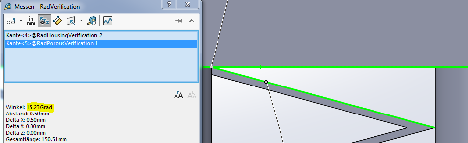
My strategy now is to use explicit feature snap and specify the exact feature refinements that i need. For example, below i have the exact angles within the fins. The first is where the fin meets the radiator housing, at 15.23 deg. I can set a feature refinement with 16 deg inclusion angle and a higher refinement level.


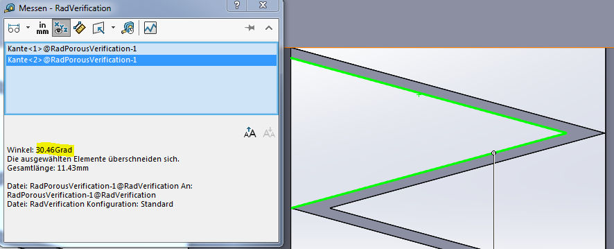
Then I can take the next fin angle of 30.46 deg, set a 31 deg inclusion angle at a lower refinement level. The first higher feature refinement will not apply itself to this area because it is outside of the predetermined inclusion angle of 16 deg.

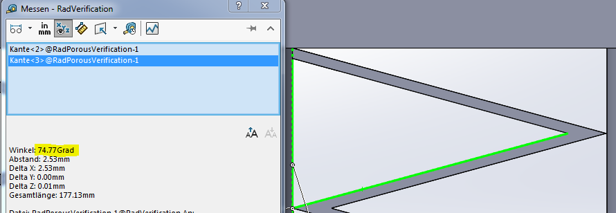
I can then continue this to the last fin angle of 74.77 deg, set inclusion angle to 75 then again a lower cell refinement.

Lastly I can set a final feature refinement to 91 deg so all remaining 90 deg faces are refined to another level.

I am not sure how well this will work due to influence of region refinements or surface refinements at a higher level then the feature refinement levels. I guess we will see

This is a GREAT exploration that you are doing…

I have tried to make sense of the Snappy snapping parameters many times, I hope this works.

I may even try this on my CyberTruck tire treads now and report back here too :slight_smile:

What i am doing is flying blind. What you do is expert and scientific analysis of these procedures and produce viable results though actual evidence. Your guidance is always needed HAHA.

LOL, then you will expect this next comment…

I will try this on a small width slice of a tire tread…

I think you should be trying your ponderings out on a geometry file of a SMALL section of your radiator so that the exploration takes magnitudes less time :wink: