Pollution exhaust in a garage

Hi @grosua

Regarding mesh independence is always a very important aspect of any CFD study, but again it depends on what kind of accuracy and deep insight you are looking for. Usually it is a no-brainer in involving it in your study I think.

I understand where you got your velocity values from, you actually showed the residuals of the velocity, but I meant what you showed in the post 4d ago, where you plot the velocity along a line in the domain.

What I would like to see is, if we plot this line multiple times, each time at a different increasing number of iteration. At some point, will it stop changing significantly. I do not know if that makes sense. So here a quick sketch of what I mean:
afbeelding
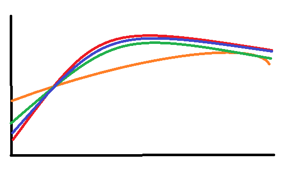
So in this graph, suppose on the horizontal axis is the x coordinate, and y axis is for example the velocity of the fluid in y direction Uy. Red line is theortically the exact solution. Orange line is solution after 3k iteration, green after 6k iteration and blue after 9k iteration for example. You can see that with increasing number of iteration you get closer and closer to the exact solution. Take note, this is not related to mesh independence, though you can make a similar study for mesh independence in this way.

So what you showed in your post is what I am looking for. If you could plot them in the same figure it would make more sense, so you can see how the 3k iteration velocity profile, is relative to the 6k and 10k and so on.

Just looking at those values, it seems like the value does not change significantly, so regarding number of iterations I think it is good.

Also the residuals you showed previously, would seem for me satisfactory regarding the convergence of the flow field, with respect to number of iterations.

So I think we can proceed with what you want to achieve initially. The test case is done for now I propose, if needed we can take a look later. I think we could now run, a more complete simulation, with the things we have learnt so far. For example the T1 relaxation factor and number of iterations?

If you tell what direction you want to go into, that might help.

Kind regards,
Tolga
Ps: sorry for late reply

2 Likes

Hi Tolga,

You are right, the mesh independence it’s a very important thing for any simulation and I understand the impact it can have in the results, but like you said it’s depending on the level of accuracy you are looking for, even though I want my results to be as close as possible to the real process, I am not looking for a high level of accuracy here because this study will not be implemented in the real life. It’s just a study, of a ventilation system which is already validated and used a lot these days, meant to prove the power of CFD in the validation process and to enhance my skills within the software.
One plus here is that I have copied an existing study, where the mesh was already tested in order to obtain decent results, this means we had a pretty good start with the previously used mesh settings.

Now it’s very clear for me what you wanted to achieve and observe with this line plots at different no of iterations. I will keep this in mind for the next simulations as it can be useful also to study mesh independence.

Indeed I should have plotted them in the same figure, so they can be easily compared, but I did;t new exactly how to do that I ParaView so plotted them independently.

Considering the important insights we learned in the test simulation and also your interpretation of the results, as you suggested, I will prepare a new simulation using 10k as no of iteration and a relaxation factor of 0.3 for the real garage.

During last week I have checked the preliminary results with my guiding teacher, and he seemed happy with the results, he also suggested a new approach for the inlets and outlets in the garage, I will also change this in the geometry and prepare it for the new simulation.

I hope that it’s more clear also for you what I am trying to achieve with this simulation. As for my thesis, I want to study the efficiency of the same ventilation system, having two adjustable levels of the fans, the first level will handle the CO dissipation (level 1- 75k m3/h) and the second level will handle the Smoke extraction (level 2-150k m3/h). Besides these two cases, I also want to add jet fans for each case, in the areas where recirculation of the air will appear, in order to improve the ventilation system. It will result in 4 simulations as follows.

Scenario 1: CO dissipation
a) default ventilation system (inlets/outlets) - current simulation we are working on
b) default ventilation system (inlets/outlets) + jet fans

Scenario 2: Smoke extraction
a) default ventilation system (inlets/outlets) - I also have started with this one in the meanwhile
b) default ventilation system (inlets/outlets) + jet fans

Thank you very much Tolga for helping me with the simulation, you are a great guy, I really appreciate your effort to help me. I will let you know when I will have some new results.

Kind regards

3 Likes

Hi @tcakir and @jousefm
I am working towards validating a Simscale-Paraview Project for my Undergraduate Capstone Project similar to the ones discussed above:
https://www.simscale.com/projects/Ali_Arafat/water_purification_process/

I have obtained the results until the velocity streamlines on ParaView but am unable to obtain the scalar distribution of water contamination. I believe it is something to do with the T1 variable however it’s unclear as to how it was done. I would be extremely grateful for your help.
The scalar distribution output is expected to look like this:


I have obtained results until this stage:

I have granted access to my project should you require it:
https://www.simscale.com/projects/ameethhp/water_purification/
You must received two invites, please refer to the latest invite. Thank you!

Hello!

The T1 parameter (Passive scalar 1 in the new post-processor) is related to the passive scalar transport model. Please refer to this page for more details.

Cheers