I am doing some practice on the following project (https://www.simscale.com/workbench/?pid=2633756712185848167&%3Bmi=run%3A3%2Csimulation%3A4&%3Bmt=SIMULATION_RUN)
as I am planning to do something similar for my dissertation thesis and I have some unclarities, I’ll be really grateful if you can help me figure them out.
First, how did you managed to get the CO concentration in PPM in the sections you posted ?? Is it a built-in feature in SimScale cause I couldn’t find it.
As I saw in the videos provided for this simulation as support, T1 represents the amount of CO in the garage, but I cannot find what’s the measuring unit for T1?
Second, I saw that you made some calculations of how much CO (2.77E-08 kg/m3 s) is initially in the garage, I was wondering where is this value taken into consideration in the simulation?
And third thing, how did you calculated the exhaust flow based on the initial CO concentration (2.77E-08 kg/m3 s) ???
I would assume that this was achieved using a script which has been used inside Paraview (or the calculator filter) - as far as I know the formula for the concentration was given somewhere in a webinar but would have to check myself first. Let me tag @anon5245009 here who might help out in this case. Doing some investigations regarding this and your other questions in the meantime!
In this case the project poster calculated a uniform distrbution of the CO of 2.77e-8 kg/(m^3 *s), hence we simply multiply the T1 result with this value and divide by the air mass in 1m^3, and finally multiply with 1000000, to get a mg/kg corresponding with ppm. I loaded the simulation results into paraview and entered “(T1 * 2.77E-08)/(1.2041) *1000000” in the calculator. This is the result for the case with the fans:
Hope that answers some of your questions. Regarding the exhaust flow, I think that it is some sort of system, that has some flow rate capability and hence the poster chose that as a boundary condition. However, you could pick any value and see how that helps the overall CO distribution. Which makes this a really cool simulation I think. That’s why I also went ahead and tried to answer your question, because otherwise I would not have seen this project.
Thank you for your time, your answers are really helpful, now it makes more sense. I wasn’t aware of the possibility to export the results and process them on different software.
As you said, there is a small difference (12ppm) between your results and the initial results in the simulation even the same results were processed in ParaView, this can have an impact on the validation of the ventilation system, so I am wondering where this difference comes from? Did you assume the value of air density at 20 degrees C right? maybe another value for density was considered? or different results were processed?
Maybe simulation master can share a thought on this ?? @anon5245009
I was quite sure that we worked with a script but the calculator is indeed the fastest and easiest way to achieve this. Also curious where this mistake comes from, would have also assumed that this is due to different density considerations.
The difference might also be in the colormap scale, I believe the original poster used a log scale, which might make it appear to be different. However, the results in paraview should always give the same values, because the data that i exported is the same, regardless of how many times I export it. Also, I just apply a simple calculation on the T1 value, so data should always give the same result in paraview.
Yes, I just googled air density at 20 c, that is the 1.2041 value. And indeed I do not know which value the orignal poster used in his results. But looking at order of magnitude I think I am pretty close to the original poster.
Hope that helps you further along the road. Would love to hear what kind of simulation you want to look into and maybe be of any help in that. You know where to find us
Thank you for taking the time to explain to me in more detail these things, it helped a lot.
I have started to work on some simulations quite similar to the one above, I want to simulate if the same ventilation system (different flowrates) installed in a garage can handle both scenarios, the dissipation of CO to a safe concentration and also the exhaust of the smoke in case of a fire.
I have started with the dissipation of the CO simulation, I used the geometry of the garage in the simulation above as a start and modified a couple of things like inlets/outlets size and position and also the layout a bit. I did these changes in Fusion 360 and then exported the geometry in STEP format to bring it back in SimScale.
I calculated the required flow rate to dissipate the CO concentration to the allowed values (100 ppm) according to the available regulations in my country. I made a duplicate of the simulation above, uploaded the new geometry and managed to create the mesh successfully, I double checked all the parameters in the new simulation to be exactly like in the one above, then tried to run the simulation but unfortunately, something went wrong and the simulation it’s crashing around 5%.
Taking into consideration that all the parameters and settings are exactly the same as the working simulation above, the only thing I assume it’s creating problems it’s the new geometry but I am not sure of this.
I am thinking maybe some errors were introduced when I adjusted the geometry and I have to use a different CAD tool to adjust it, any recommandations would be really helpful.
Please let me know your thoughts on this, thank you a lot.
Thank you a lot for your quick reply.
Yes that’s true, I downloaded the geometry made the modifications stated above and reupload it in the SimScale project.
Sorry, I think I forget to make the project public so you can access it, you may give it try now if you have the time.
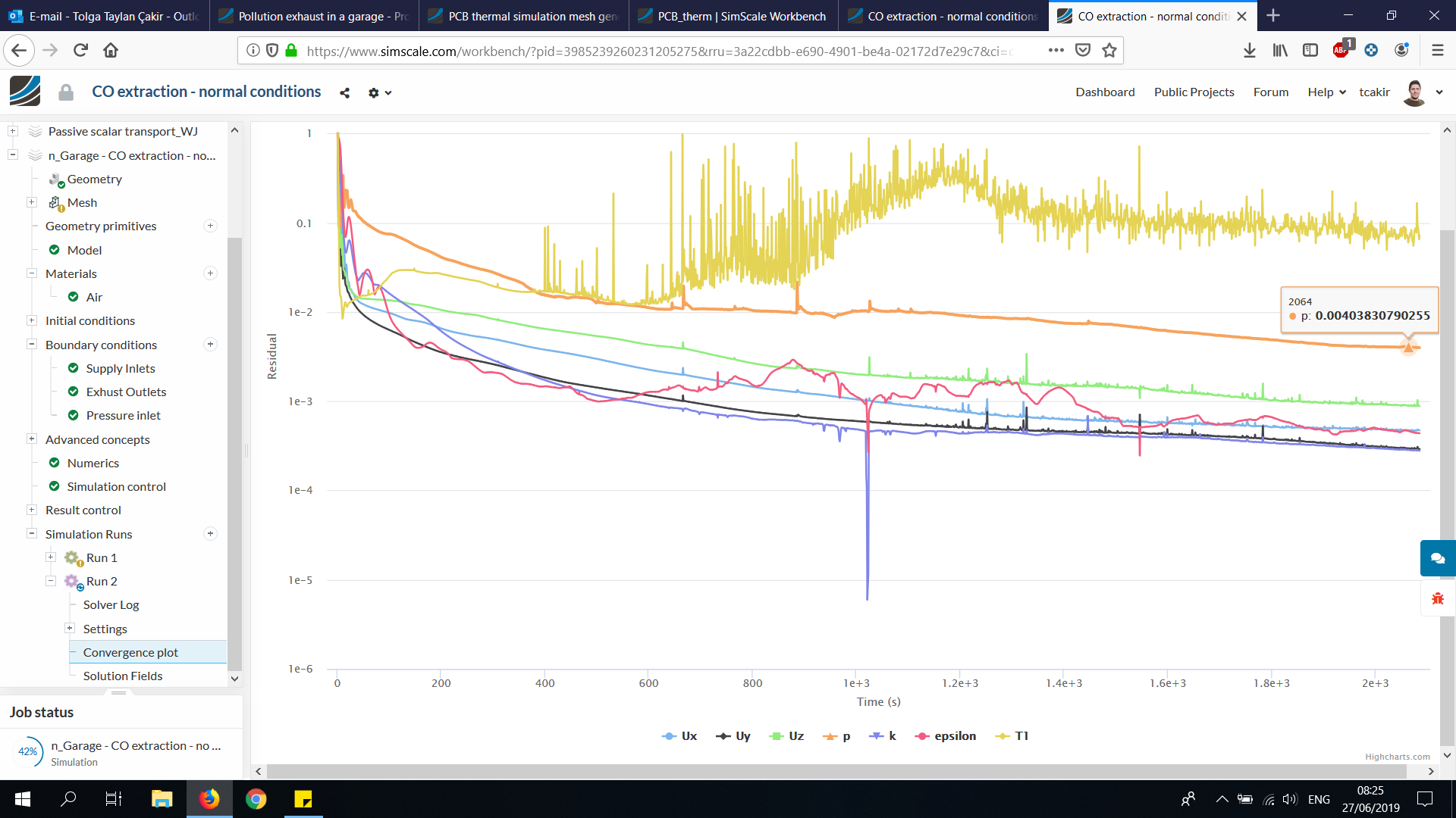
I changed some relaxation factors in the Numerics tab , to the same value as Run6_jetFAns of the original project. Also in that Run6_jetFans the passive scalar seemed to show similar convergence behaviour, that it is does not keep decreasing, but instead increseas and decreases and is very oscillatory.
@grosua I have invited you to my project, so you can see the progress yourself too.
No worries @grosua . It is a pleasure to help out. I should have indicate my inavailability suddenly. This week has been a bit hectic in terms of work. Let’s see how the simulation goes and hopefully it will give satisfactory results .
The simulation it’s done, I have checked out the results this morning, and it seems like all the parameters except T1 converged really well, besides this the values for T1 are way higher than in the initial simulation (T1 initial around 6k, T1 in this simulation is 150k ) this is a bit strange considering that the values for inlets and outlets are quite similar and the geometry it’s pretty much the same. What do you think ?
Another strange thing, is that when I create a cut plane to check the concentration of the smoke in the garage (T1 cut plane at 2.8 m or other value) there is only blue color on it, meaning the concentration is the same in the entire garage. What could be the problem ? Is the scale messed up ? Do you think I should run the simulation longer ? like 10000 s ?
I am planning to do some more changes to the geometry according to my country norms and then to start the simulation from the beginning, if you think there is something I can change (geometry or numeric values) to improve it please let me know.
Hi @grosua
Indeed T1 is very oscillatory and did not converge as nice as the other variables. We could try to go for 10k iterations, that would be a start .
I will have to investigate the difference in T1 values, I am thinking it is the scale, but I need to check to be sure. I also tried using a cut plane, I will need to post process on my own laptop later, to see if it is the scale or not.
Assuming the other variables converged nicely, I do not think there is any problem in the geometry or so. However, do note that in the original project, the T1 was also very oscillatory, and I do not know for sure why T1 is not converging so nicely. I will look tonight what causes these problems. After that I suggest we run a 10-15k iterations, and see if T1 converges toward below 0.01, or possibly 0.001.
I will also compare the other succesful sim results of the original project, and see if T1 converged better. Maybe some numeric setting.