Dale, I re-read this post and found this from Dylan to be potential problem in my meshing. He says that a HIGHER Region refinement will increase the surface refinement level but will this also happen if the region refinement is LOWER then the surface refinement?
![]()
Sorry my bad. In the refinement settings, you can define refinement levels on the fuselage, the wings, and landing gears, etc. You can also define refinement levels on a box that covers the plane, so that the cells within the box will have at least that refinement level. For example, with a background mesh of 0.5m generated from blockMesh, you can define level 8 refinement on the plane, and level 6 refinement on a box that covers the plane. Now, if you define a level 9 refinement on the box, then the entire plane will also have level 9 refinement, finer than what you need creating a lot of cells.
When doing mesh independency study, you can increase the level of refinement of that box to 7, but you don’t need to increase the level on the plane. If there are areas on the plane that are apparently not described by the surface mesh properly, then you refine it.
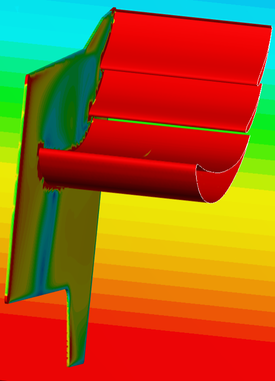
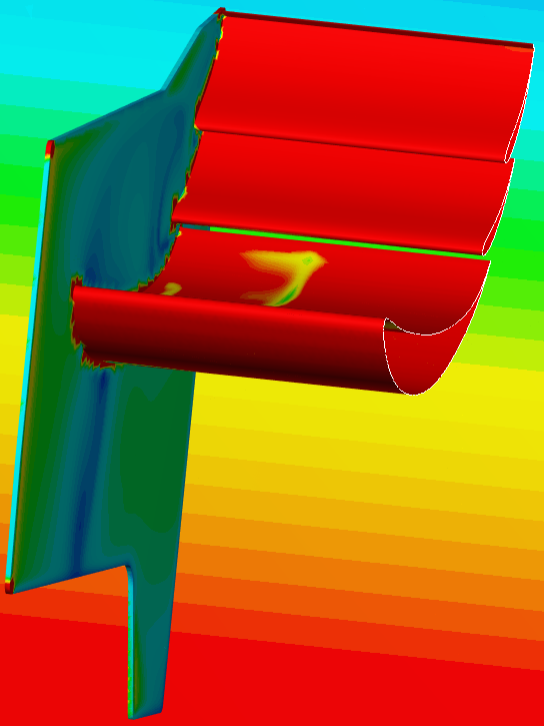
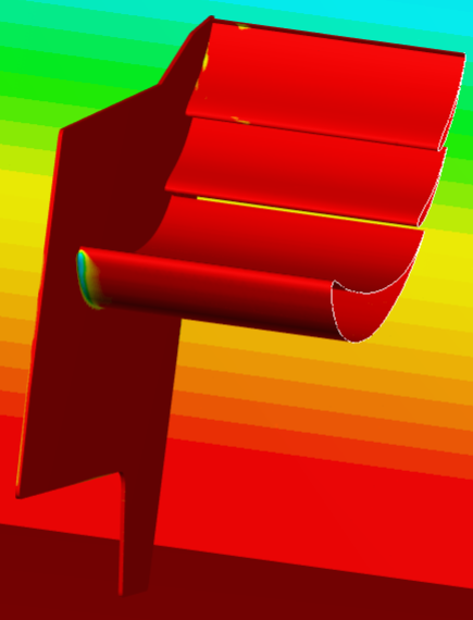
After a test of only the Rear Wing, using the following settings, it seems that the region refinement effected the surface refinement level by lowering it back down to level 6.
RW Test 1.0
Surface refinements
- Wing surfaces at level 8 - 0.00375
- Wing trailing edge surfaces at level 11 - 0.00046875m
- Endplate surfaces at level 6 - 0.0015
- Endplate and gurney flap edges at level 10 - 0.0009475
Region refinements
- Close to model cartesian box - Level 6 - 0.015
- Cell reduction cartesian box - Level 4 - 0.06
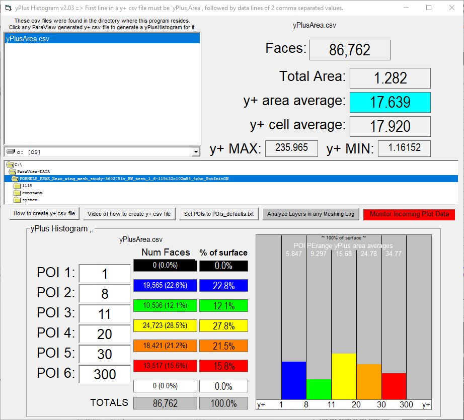
| Inflate boundary layer settings - layer calculation | Y+ Value | |
|---|---|---|
| Layers | 4 | |
| 1st | 0.000647 | Y+ = 30 |
| 2nd | 0.00106755 | |
| 3rd | 0.001761 | |
| 4th | 0.002906 | |
| Overall thickness | 0.006381 | Y+ = 296 |
| Expansion ratio | 1.65 | |
| Min thickness | 0.001m | |
| Final layer thickness (RATIO) | 0.775 | |
| Inflate Boundary Layer settings - changes in Final layer thickness (RATIO) |
- Wing surfaces - 0.775
- Wing trailing edge surfaces - 6.199
- Endplate surfaces - 0.1937
- Endplate and gurney flap edges - 3.06
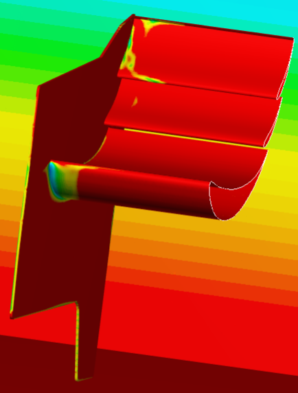
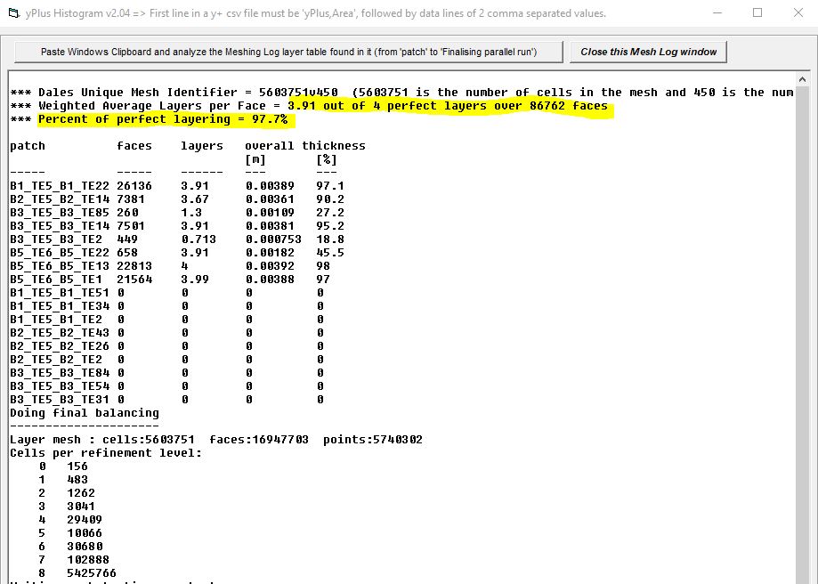
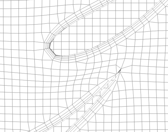
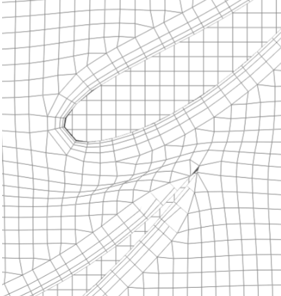
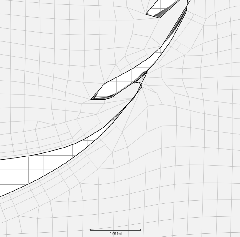
Region refinement level was not lower than the surface refinement which causes the whole model to obtain region refinement level. This can be seen by observing the mesh and in the meshing log which shows only level 6 was achieved.
Layer mesh : cells:139885 faces:433057 points:153466
Cells per refinement level:
0 156
1 483
2 1262
3 3041
4 30329
5 7816
6 96798
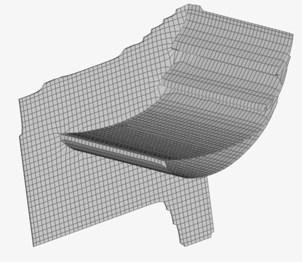
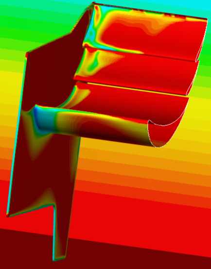
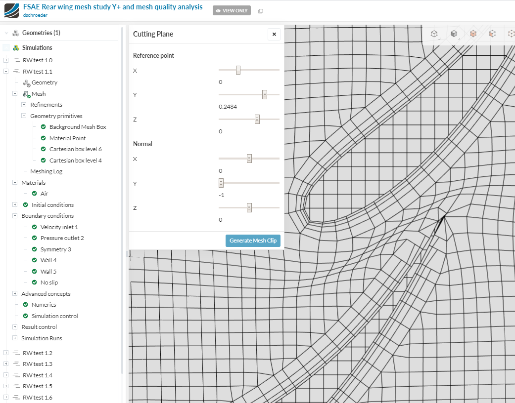
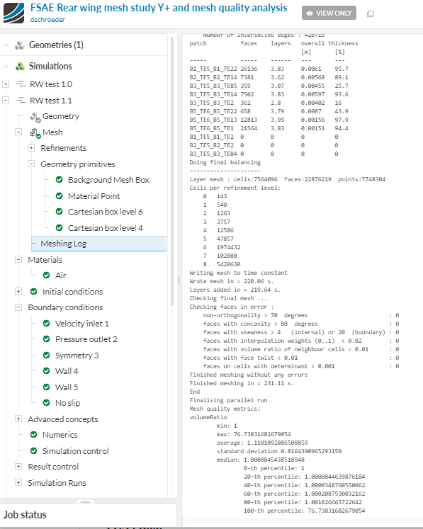
RW test 1.1
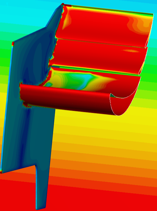
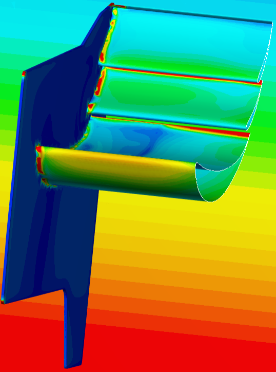
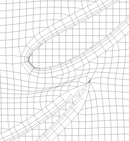
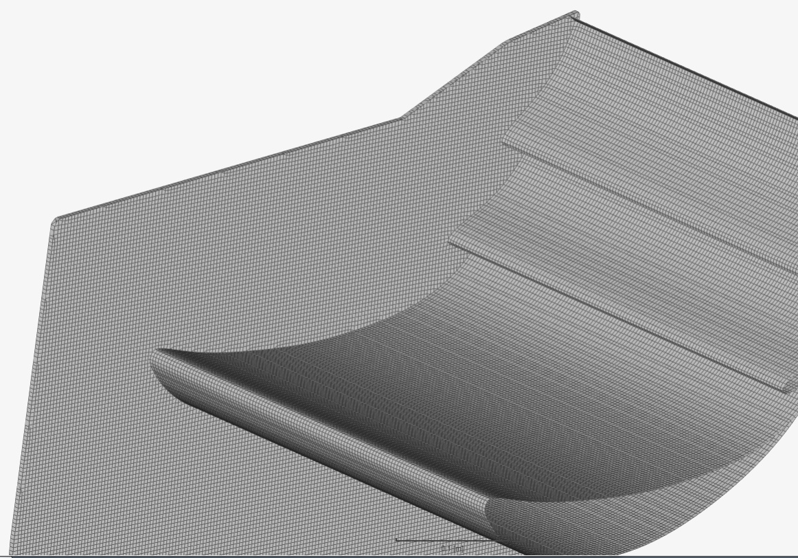
By increasing the region refinement to level 8, the mesh conformed much better but lower level areas (endplate small edges, gurney flaps, wing trailing edges) are also changed to level 8 cell size- 0.00375
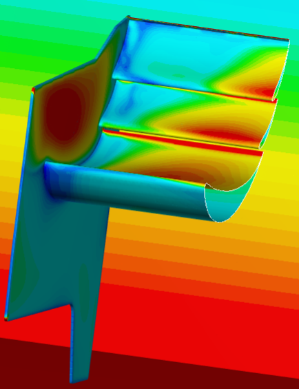
Another problem is just this rear wing mesh has 7.6 million cells - waay too much
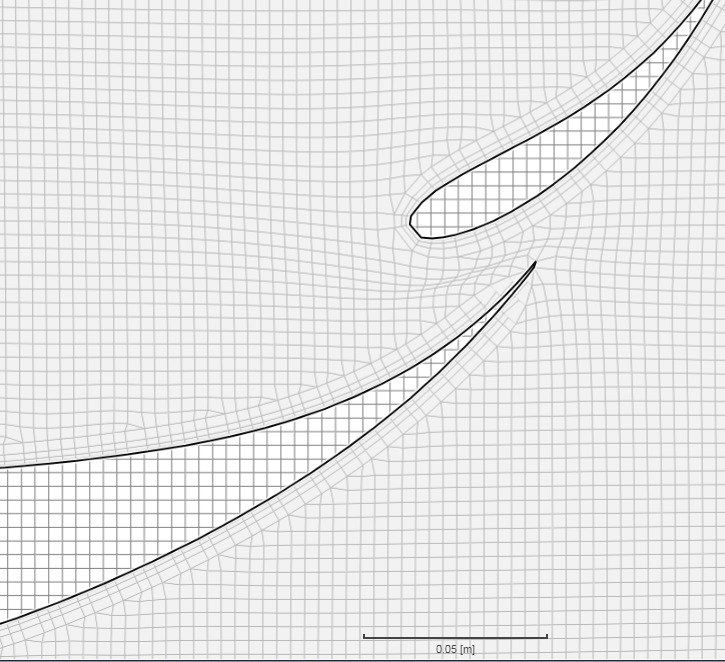
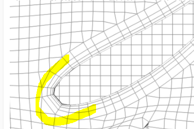
Gurney flap not meshed very well - was set to level 10 - 0.0009475 surface refinement

I have also tried no region refinements, with a high level change between cells, but that resulted in the wing not even being meshed.
I am also trying just one universal boundary layer inflation, and will also try having the smaller faces with unequal level refinements.