Nice. Thanks for explaining all that, but why are we making our new final iteration, that would give us the visual output (solutions field results) at this final value of 0.2187 at iteration 1521?
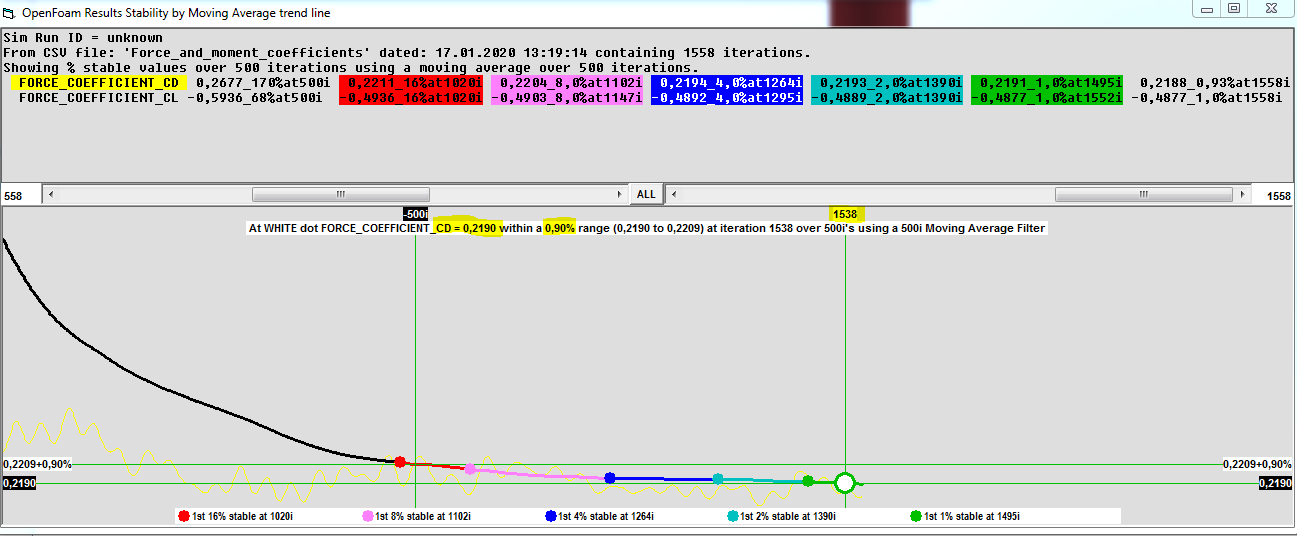
Wouldnt it be better to use a final iteration that is even closer to the ORSI %. which is found by moving the slider to the lowest % difference. In the next picture it shows 0.90% range at iteration 1538 at Cd = 0.2190. Im not saying that 0.03% is such a big difference but maybe in future simulations there will be a bigger jump and the visual data will be that much more accurate.
Because, that is the ORSI value that is the solvers best guess, we should present the full solution set of data that would integrate the viscous and pressure drag on all the geometry surface faces to the same value as ORSI is…
Actually at 4 significant digits it is 0.2188, not 0.2187 
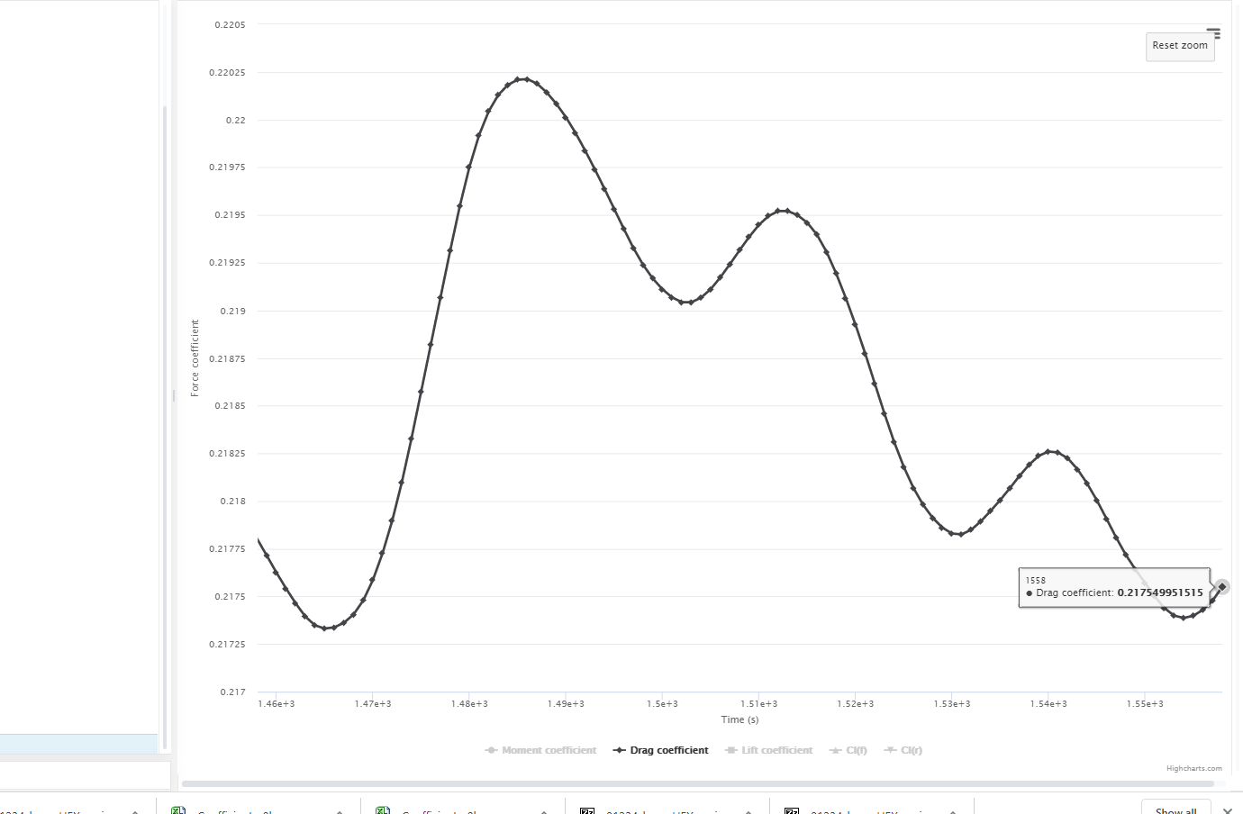
If you just take the full set solution data at the last iteration at it would integrate in ParaView to CD of 0.2175 as you see here:
Which is 0.6% different in this case (you were lucky, on data that oscillates more we have seen that it could be 5-10% off)…
I am using the ORSI at 1558 0.93% but we have to look back to find an iteration that matches our best ORSI % stable, which is 1521.
Splitting hairs you could use 1538 0.90%, but I am sure that last iteration 0.93% is fine and easier to understand as a procedure, and there is an argument that can be made that the last iteration ORSI at high MA iterations is always the best guess of that sim run.
Also, I really want to stay close to that last iteration for scrutiny purposes (that goes for how MUCH earlier we find a close iteration, I would rather choose a close iteration at 0.2189 than a further away iteration at 0.2188)
As far as my ‘at high MA iterations’ edit I made above goes… My procedure for determining how large a MA iteration value to use, is currently, that the MA line (non-yellow line) should be horizontal at the end of it, if the MA line is not stable (horizontal) at the end, then you should lower the MA iteration value or run the sim to more iterations… The MA iterations value determines how well oscillations are filtered out of the data.
ok great! now the procedure is official! How do you feel about me still using 1 BL layer at 3.4mm? Should i do your 0,1,2,3,4 layer test on the full car? I would exclude 0 layers though.
Yes, you noticed that 1 layer is back in the game 
I think my post #334 describing my 01234 test should be sufficient justification for you to use 1 layer (unless someone finds a hole in my project)…
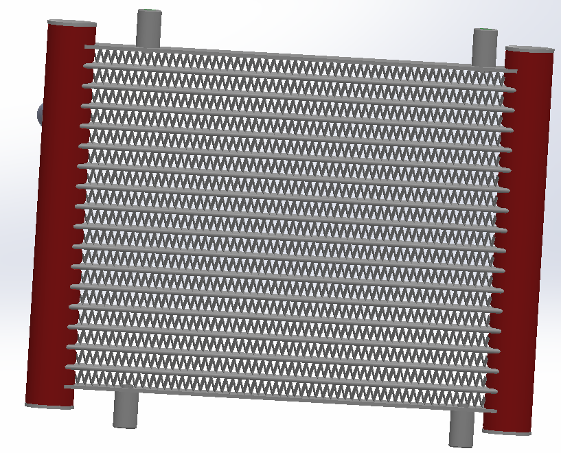
awesome. Now i have a lot of work to do (as always) getting the final geometry ready. Im going to try the next run with meshing the actual radiator. Well see how that goes. I dont think i need a BL refinement on it though what are your thoughts? i still have to clean it up a bit and remove the inlet and outlet tubes.
After the radiator sim run ill add a rotating fan as an exhaust
Actually a 1 layer BL should mesh on most anything that has sufficient gap, worth a try, even low % layered with 1 layer is better than no layer (it appears so)… We are on new ground here 
Not sure if 1 layer test works on full resolution y+1 meshes, maybe another test is needed
A 1 layer y+1 mesh would likely easily mesh those radiator holes…
EDIT: another benefit of 1 layer meshes is that they have very low illegal cells…
Yea the zig-zag mesh is 0.2mm so i could just apply the appropriate surface refinement and use the calculator for a Y+=1 first cell size. Ill post what happens
Looks like you are squished for time, so the standard approach would be no layering, but I see level 13 or 14 coming here regardless, I doubt you will have much luck with that if you want to add it to the car mesh…
I just noticed on your latest full car mesh and sim setup, I think you should add an ‘Active Tunnel’ cartesian box sized and refined like in my 01234 test… it presents the inflow to the car and resolves the downstrean wake much better and does not add t too many cells…
I am exporting from ParaView the yplus csv file right now for that sim run, I just remembered how I determine when ParaView is done exporting, I just open a Task Manager and wait until that ParaView windows stops showing as ‘Not Responding’
So you dont think adding this radiator to the car mesh will work? Is it too small or what.
Yea layering isnt really necessary because im not taking data from the radiator at this point. Just to simulate the constricted flow.
So you would say a level 3 refinement is enough to encapsulate wake and pre-car incoming air
I think I used L3 and it looked OK to me in the results images, but again these things get optimized when you really want optimum results.
I think everything is possible, that is one of my problems
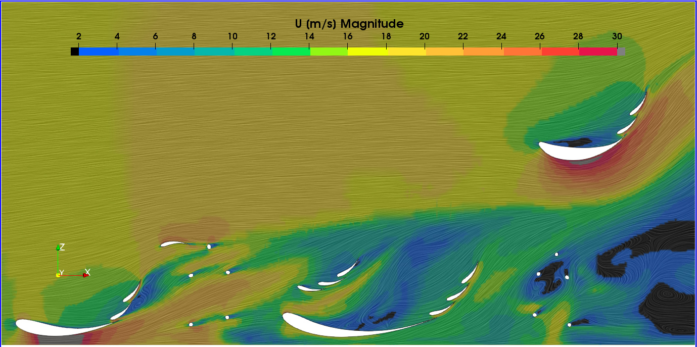
If we can believe the sim results, it looks like you need to re-set some wing angles and locations to get flow attached and make some real downforce:
You should start including some force results items for all the wings, so you can see each wing/sets contribution to down force…
WOW that looks awesome! I have to get up to speed on creating these surface LIC slices. It looks like the flow detaches mainly at the front wing. unfortunately i am doing this project on the already build 2019 car. So changing AOAs on the elements is a no-go. YET i did design the front and rear wing as a whole group to change position in X and Y, and also AOA. This is what my project is about … changing the pressures of front/rear wing in order to change the center of pressure location. Then record the changes and see how much lateral acceleration improves.
Also forces and moments plots are in this simulation run. I have and ALL plot and a Sprung mass Plot (which is without the tires and motors to see “True” downforce.) Comparing the Sprung mass lift/drag numbers to the results we get from the sensors on each damper system, we can determine if real world results match CFD
for individual wing groups, yes, i need to add the forces and moments of these
I only see Force results items for ALL and Sprung Mass…
I don’t think you understand… You need to create a separate Forces items for the ‘FrontWingGroup’ and ‘RearWingGroup’ and include only the wing surfaces in the face selection for the group (maybe the end plate surfaces too if they move with the wings when you change AOA)… That way OpenFoam does the force integration for you during its run and you don’t have to do it in ParaView…
I did not realize this car exists… that is good for you as you can drive at sim run speed with a few locations grid tufted and see if the flow at the surface is separated and which direction it flows… a great opportunity to test and locally verify the predicted CFD flow patterns at least 
Oops I think you edited as I typed, but I will leave this…
yea i added the edit at the end. Yes last year i had forces and moments as separate selections for all wing groups.
Also as a side note. I did not look at separation on the front wing in a straight ahead simulation because after the first few design changes, the entire aero package was developed in a turning situation. So, 0.56deg roll, 10 deg tire angle etc…
When you get to the sim setup for turning flow around the car, I have some ideas on that… Do you have a sim run for turning flow you can point me to from last year?
yea i can send you the link to last years simulations. Were you thinking the MRF style cylindrical style wind tunnel. I read that thread
1 Like
Yes, MRF… If you want to keep it private, just share the private one with me…
here it is i just made it public … shouldnt be a problem. Second to last run is our final run
COOL, I can play with that
Since you guys only saved your forces results every 5 iterations last year, I had to use ORSI 100i30mai to make it give similar results to every iteration saves:
This brings up a point, for ORSI, only ONE forces (preferably a coefficients) results item of all faces needs 1 iteration saves… For any others, there is no problem making them save every 5 or more (unless you want to ORSI them accurately, which you probably do, so you can ignore this note that could save core hours…), which would save core hours during the sim run…
EDIT: What FSAE team are you with and how did you do last year 
Also, you really should try my MRF idea…
So based on the ORSI of the last years car, we did have 1% stability in the results… thats good to know
Yes for the coefficients i will do 1 iteration saves. I do have a decent amount of core hours, I dont plan on using a lot as i need to do maybe 10 -15 full car simulations total.
I am with the FSAE team Raceyard from Kiel Germany, The account is Raceyard53 as you have probably seen. We did ok last year, there are always problems with the car working properly/being completed on time. The team has a lot of advanced systems but isnt very good at time management or keeping deadlines. This caused the 2018 car to not run at any events and last years car only started working towards the end of the season. Its too bad because we loose a lot of points at the design events due to having nothing on the car validated.
I would love to try your MRF idea. I read also the Curved wind tunnel thread Cornering Aerodynamics with Simscale
And the PDF within this thread Here
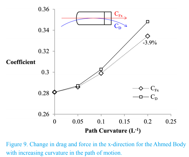
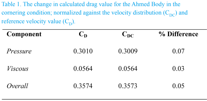
In the PDF it shows the following graphs towards the end. While i would love to experiment with the model in a curved wind tunnel, I have a few reasons NOT to peruse this test which are explained at the end.
With this summary at the end;
Summary
The cornering condition can have a significant effect on aerodynamic
performance of vehicles but is unable to be represented
experimentally. Experimental solutions developed for dynamic
motion of aircraft are not readily adaptable for automotive bodies.
The close ground proximity, high blockage ratio and the specific type
of motion all add complexity which increases the difficulty of
achieving the required flow conditions.
Fortunately numerical simulation permits investigation into the
condition. However aerodynamicists must remain aware of the
change affected by this condition. Numerical simulation must
accommodate curved flow occurring within a non-inertial reference
frame, and this requires additional considerations when constructing
such models. Due to the motion, drag begins to act in a curved path
and variation in Re occurs within the domain. Results highlight the
importance of adopting the correct analysis techniques when
evaluating aerodynamic performance for cornering vehicles.
Reasons not to do Curved wind tunnel test
- This difference in data, to me, seems fairly minimal in comparison to a straight wind tunnel.
- These tests on the Ahmed body are at 25 m/s. This is quite fast for what our car will be seeing on the track. My tests would include-
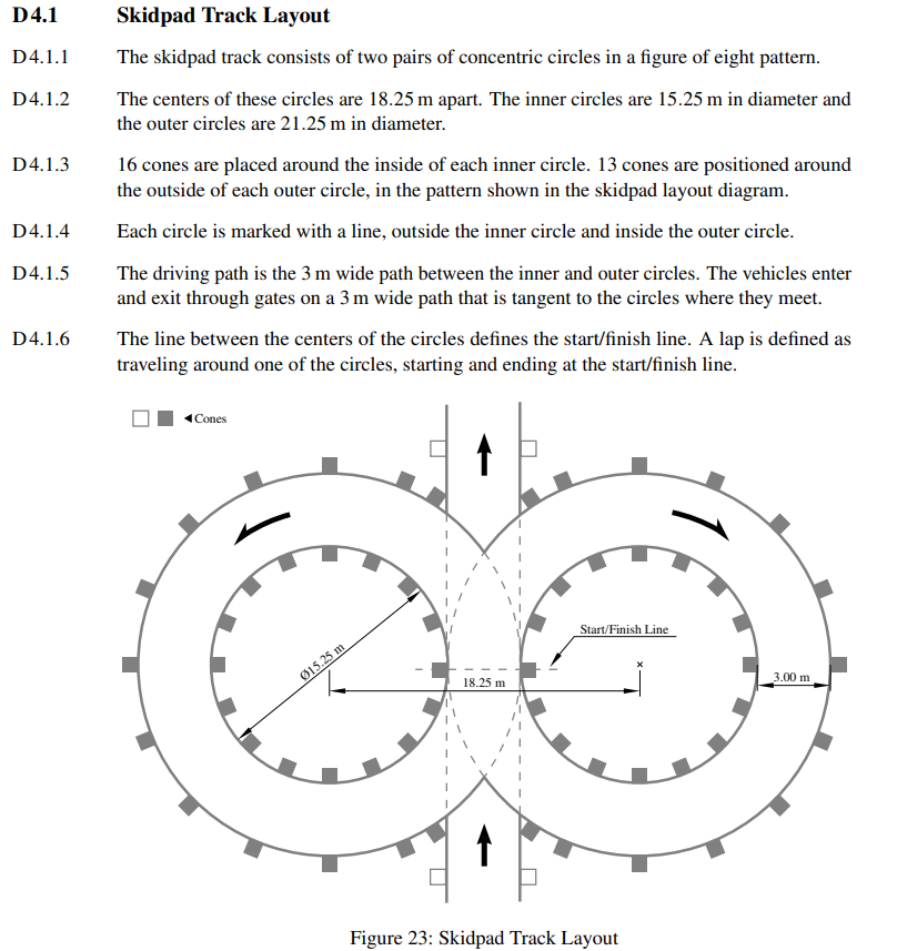
a. Official skid pad event inner radius at 7.625 meters
b. Low speed skid pad test at around 4-5 meters
c. High speed skid pad test at around 10-12 meters
-
(cont.) Therefore, outside of the higher speed skid pad, i do not see our cornering speed exceeding 20-22 m/s as most of the turns on the FSG track are slower speed turns. I have been using 18.06m/s for previous inlet velocity tests because this is the average speed for all turns on the track. Optimizing the car by simulating low and high speed cornering situations was not possible last year because i was the only one in the Aero team for the design phase. I simply didnt have enough time.
-
Speaking of not having enough time, my last reason is just that. If we can justify that a straight on simulation ( including the pitch, yaw, roll, and steering input changes for each skid pad trial) are enough to have accurate results within reason. I would vote to leave it as a straight wind tunnel simulating the car in those pre-set cornering angles.
Basically - is this worth the trouble? Are the results that much more accurate that we NEED to do this?