Not able to overcome error "Time step bigger than the given simulation interval."

I am trying to get the reaction force from a fixed support in a displacement controlled compression test on a sandwich structure. There are 4 parts- Skin, Core top, core bottom and bottom skin. The core is interlocking.

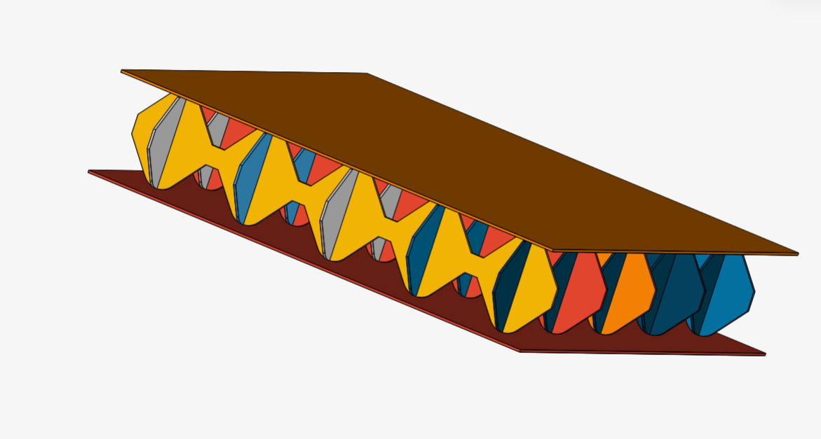
Physical contacts have been defined between- top skin-core , Top core- bottom core and bottom core-skin.

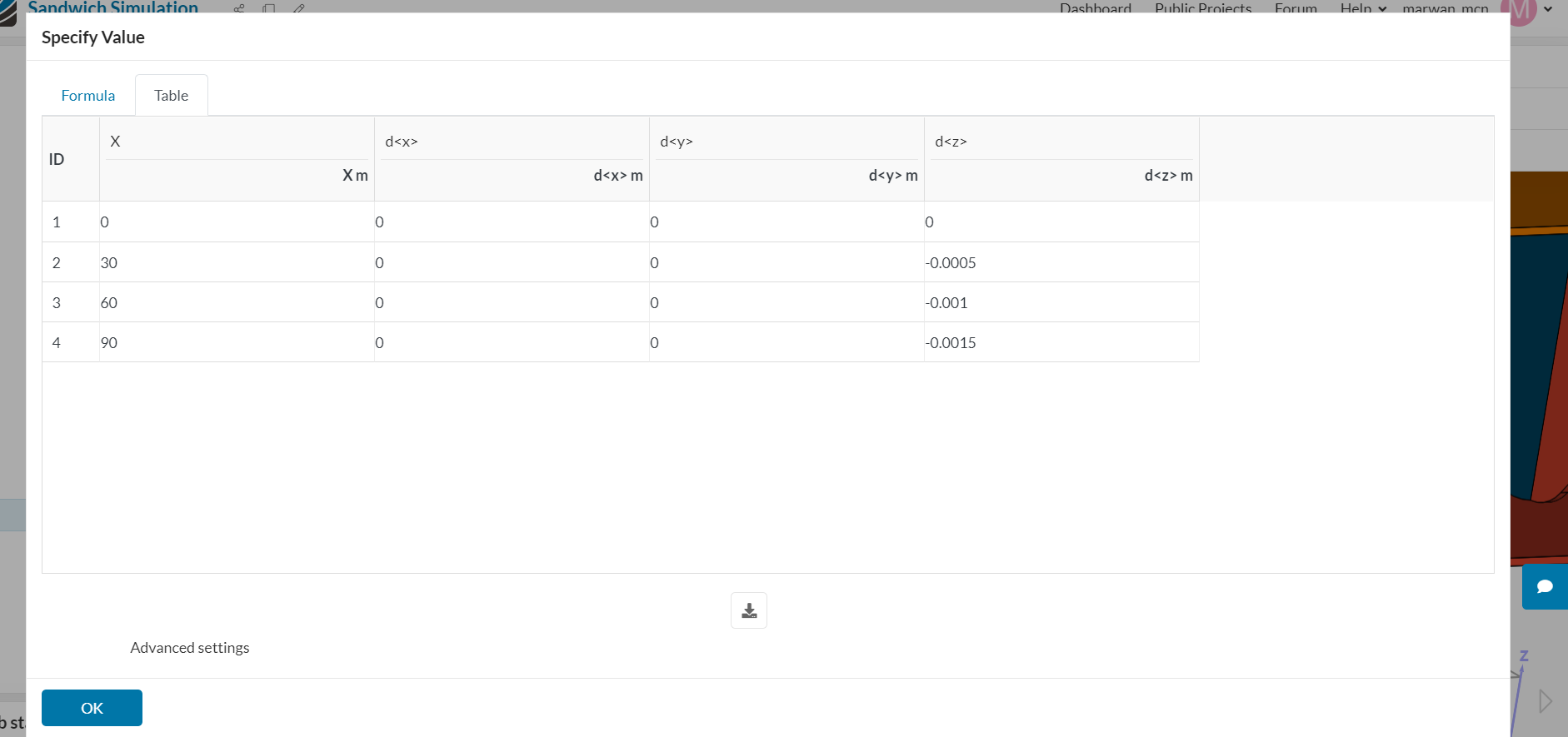
The displacement is applied as a fixed value to the top skin. Applied as a table and with intention of giving displacement rate as 1mm/min ( still assuming that the rate will not have affect as static analysis).

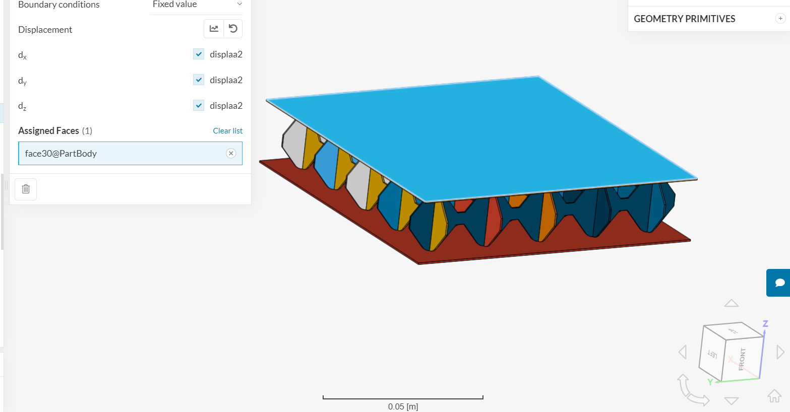
This is the table for displacement. Negative displacement in Z direction is assigned to get compression.

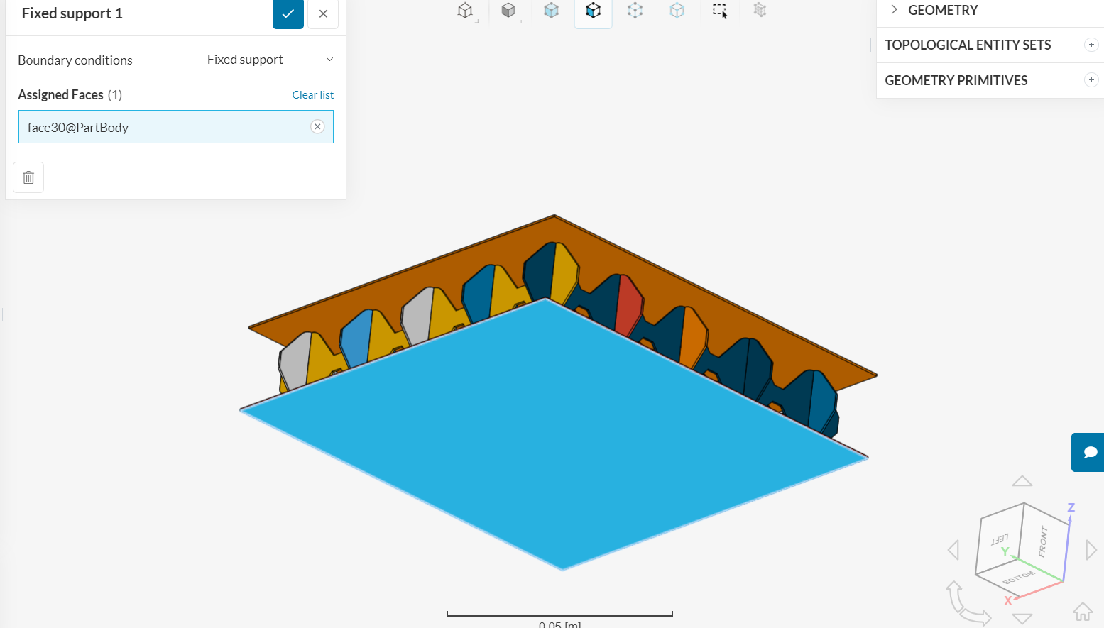
Fixed support is assigned at bottom face of bottom skin. This is the support where reaction force is probed for.

Elastic supports have been added to the core surface which is close to the contact area to the skin. This ensures no rigid body motion from slipping.

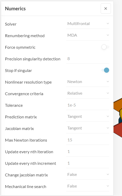
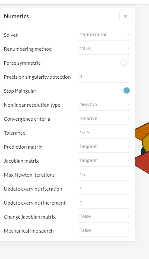
The solver i have opted for is the PETSC solver.

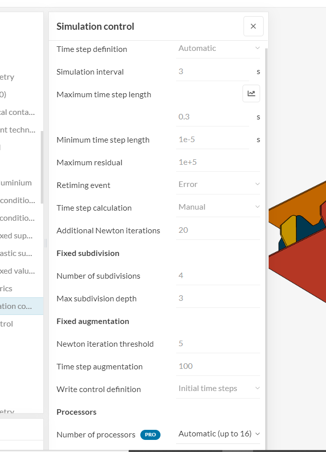
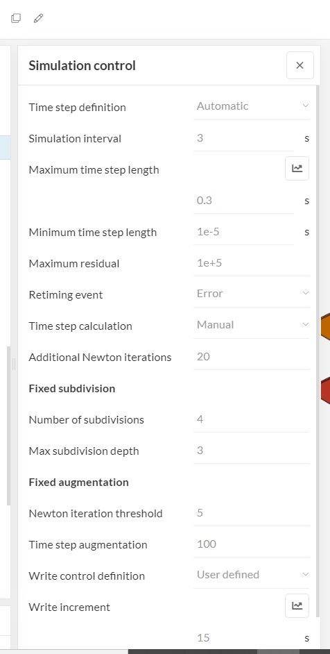
The simulation controls have been changed to -

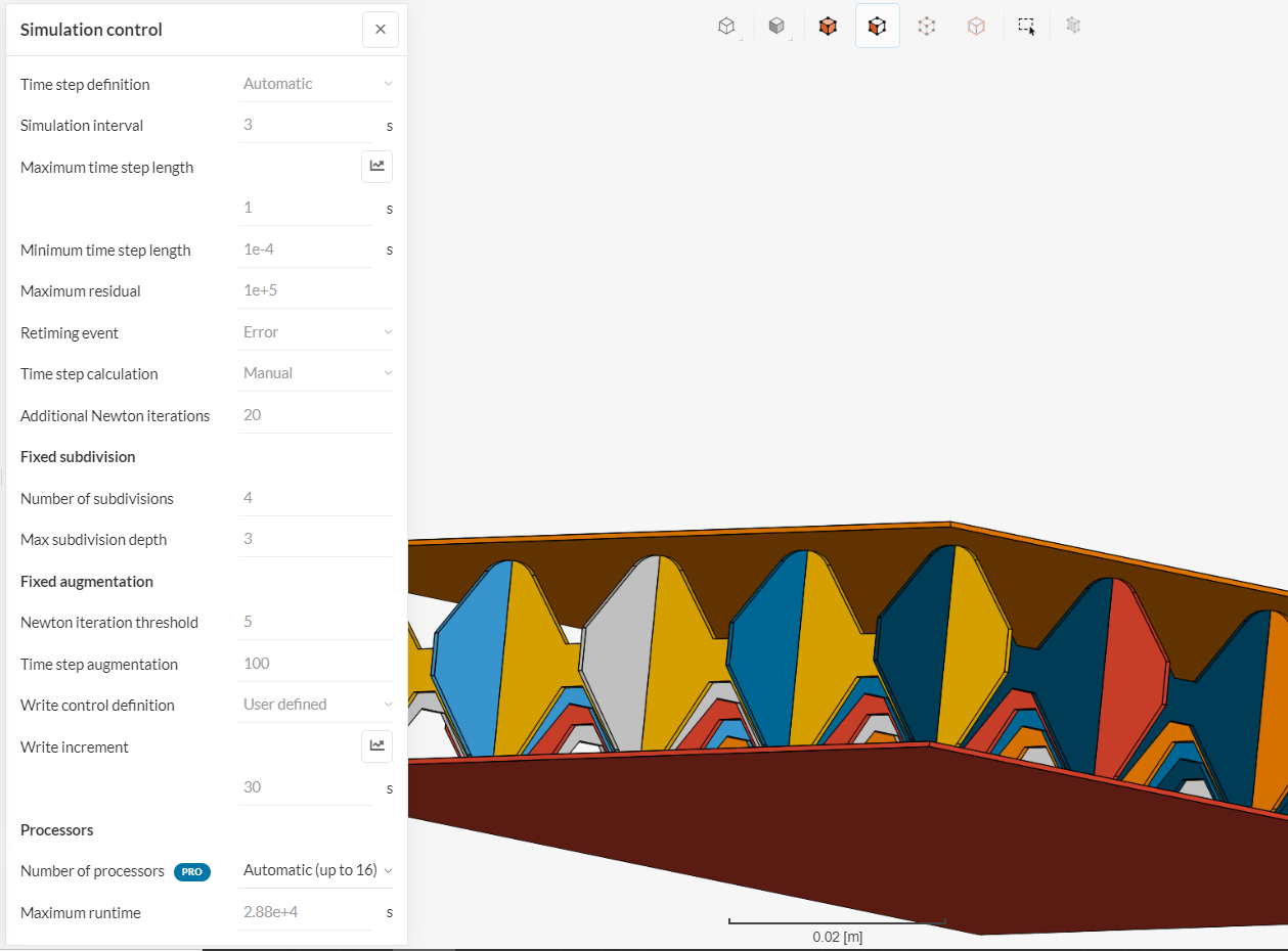
I have have changed the simulation interval to 3 seconds as i assumed it would break each of my displacement periods of 30 secs into 3 secs and thereby get 10 steps. This was the only understanding of simulation i could get from reading the documentation and help pop up.
The maximum time step length was also increased as my understanding of the parameter is that if increased it should reduce computation time.

Also i have observed that the simulation fails after longer when i use the initial time steps setting for write control definition instead of using the user defined option.

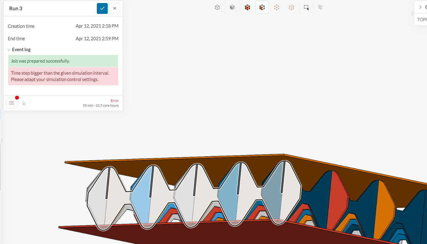
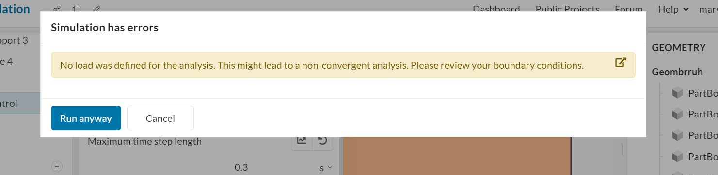
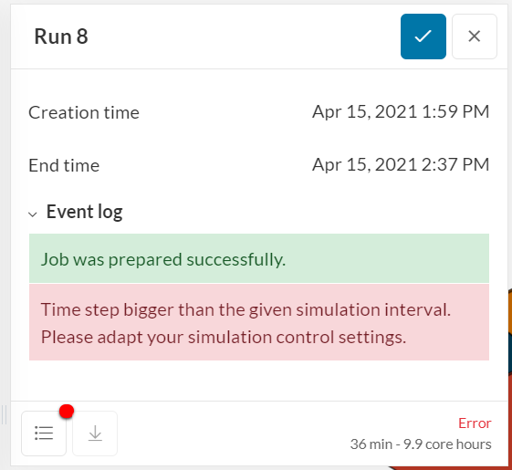
“Time step bigger than the given simulation interval. Please adapt your simulation control settings.”
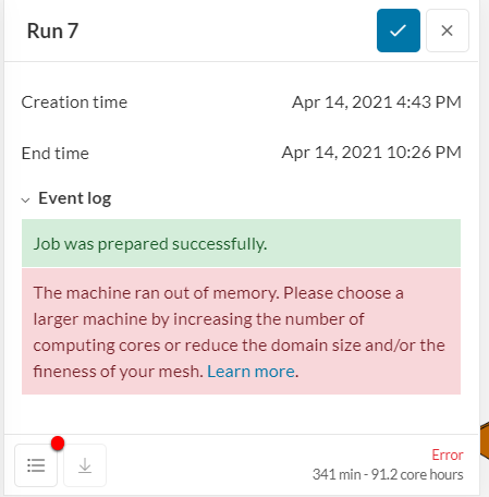
The above error was in Run 3 for the “disp_change” analysis in my_project

In run 5 i tried using the Multifrontal solver and reduced the max time step length to 0.05s and still got the same error.

Could it be explained what each of the simulation control settings mean and how they affect the results and how can i get through this error ?

Thank you

1 Like

Hey there! Thanks for making use of our forum!

To answer your main question, please refer to the following doc:

If something is not clear, please feel free to let me know so we can improve it.

Basically, the integration starts at time zero, then increments with the ‘Maximum time step’, and goes on until the ‘Simulation interval’ is reached. If automatic time step cutting is used, then upon convergence errors the time step will be subdivided into smaller steps, this is why it is called ‘maximum’.

That being said, the error happens because your time step is bigger than the simulation interval (end time), which makes no sense. What you should do is to use it to control the subdivisions in the integrated interval, for instance the default is to use 10 0.1s steps over the 1s range.

I also noticed some improvement opportunities on your setup:

Notice that your displacement depends on the X coordinate, while it should depend on time. Also, make the time values consistent with your simulation interval.

An imprint operation will help you with the bonded contacts, please do it:

To avoid conflicts between the contact definitions, try setting the slave assignments of the physical contacts to the plates.

I would remove the ‘Core’ physical contact to avoid conflicts with the other contacts.

Also, there is no need to change the solver choice, the default Numeric parameters should be enough for this case. The only required change is due to the displacement control, which is to set Numerics - Convergence criteria to Absolute (residual).

1 Like

I went through the simulation control documentation. A doubt that I had was for example if I consider my model in which the top plate is given fixed values for time 0, 30, 60, 90 seconds and apply a simulation interval of 3 seconds for it, will the solution for a period between two specified fixed values ( example from 30-60 s ) be broken down into 10 intervals of 3 seconds ( 30-33-36-…57-60).

Moreover in run 8 for disp_change simulation i have gotten the same error. This is after applying the max time step as 0.1 of the simulation interval ( sim inter- 3s , max time step- 0.3s). I have even corrected the mistake of using the X coordinate instead of time in the fixed value table definition.
Could you elaborate on the suggestion " make the time values consistent with your simulation interval".

Also i have used the “Core” physical contact to define non linear contact between the interlocking core plates ( 10 plates ). Which is why I have not used bonded contact.

Trying the different option for the convergence criteria in the next run.

In the physical contacts i have assigned the slave to square plate for both top and bottom instance. I would have preferred to use the bottom square plate as master as the plate is essentially fixed and the core moves into the bottom square plate and as per the documentation the part that penetrates the other one is to be considered as the slave assignment. However i got this error,

“The slave entities of two contact definitions share nodes. If the same entity is not assigned as a slave, this might be caused by shared edges. To obtain a valid configuration, make sure not to assign two adjacent faces as the slave entity for different physical contacts”
My understanding of this error was that the core plates when assigned as slave in the ‘core’ and bottom contact they had shared nodes.,
So i settled for using the square plate as slave at the bottom. Would help to get better clarity in the slave and master assignment so that i can still assign the square plate at bottom as master.

Thank you

One more thing.

I get this warning before the start. Thing is that my test is a displacement controlled test and i need to recover data for load reaction. What could be improved to fix this

This is just a warning. As you know what you are doing, you can run without concern.

Thank you. I shall ignore the no load error for now.

Could you please check this reply out. Includes my doubts related to error coming even after taking the precautions such as applying the simulation interval and max time step length at a ratio of 10:1. Moreover i have included my query where i aim to use the bottom square plate as master. ( not being able to use the setting as slave entities share nodes in more than one physical contact definition)

Thank you

I can see you have some misunderstandings. We all learn in different ways!

Please analyse our nonlinear simulation tutorial, and maybe you can make sense of the time schemes and how the setup should be done:

1 Like

In run 7 and run 8 in simulation ‘disp_change’ I have used the same settings except for the write control definition… In both the runs the simulation interval is 10 times the maximum time step and its same for both run 7 and 8.

Run 7


The write control definition is set to ‘initial time steps’.

run_7
This is the error i get.

Run 8


The write control definition is set to ‘user defined’.

We get the time step error here.

Why does using ‘user defined’ write definition give me this error. Also i am trying to use this as i had gotten this error in one of the previous runs.

instance_err

Two things:

  • Why do you say that your simulation interval is 10 s but in the Simulation control images, it is 3 s?

  • The ‘out of memory’ error is due to a combination of mesh size, number of output steps and machine size limitation (due to community plan). You can reduce mesh size or number of output steps to try and overcome the error.

I was trying to explain that the simulation interval is 10 times the max time step length, and i was mentioning this because you had stated the default is 10 0.1s over 1s. Was trying to implement the same ratio of simulation interval to maximum time step length.
To overcome the ‘out of memory’ error I was trying to use the ‘user-defined’ option for the write control definition in the simulation controls. And every time I did this ( i.e. , change from default option of ‘initial time steps’ to ‘user-defined’) the error would be “Time step bigger than the given simulation interval”.
Which is why the doubt came up in my mind. Why does changing the write control definition have an effect on whether or not the simulation interval is bigger than the maximum time step? And that too when we haven’t changed any other parameter such as simulation interval input , max time step length etc which have a clear effect on the time step being smaller than the simulation interval?

If you specify a time step to be written on the results, the solver has to go to that time step to compute the solution and add it on the output. Thus, the write control also has to be consistent with the simulation interval.

1 Like