I have been trying to mesh my geometry but I get a mesh with no connectivity. I checked with higher levels of refinement but that didnt help. I checked my geometry and I see that most of the surfaces that are imported have some sort of tessellation. Is that the reason ? if yes, how can I get rid of it ? I tried using solidworks to export the model in iges with NURBS but it doesnt work either. Here’s a link to my project newtest by cecil_pabbathi | SimScale
Thanks for the quick reply. I can export the model alone as stl but on my cad program I am not able to create an enclosure around my stl body and subtract the body from the solid and export it as a single part. And if am correct stl cannot export multiple solids right ?
I’m not sure what kind of problems is occurring in your case.
But I present 3 answers of problems and solutions for using STL.
Model must be solid on CAD
Multiple solids in one STL file
Spliting a STL solid model into different surfaces on SimScale
It would be nice if there were answers to solve your problem.
If there is nothing to solve the problem, please tell us again.
1. Model must be solid on CAD
Whichever CAD file format you use for CFD,
the original model should be a solid or closed surfaces.
If it is not a solid or closed surfaces, you need to close the hole first.
2. Multiple solids in one STL file
I use Rhinoceros for modeling surfaces.
Rhino can export just only one solid object for one STL file.
But you can combine multiple STL files into one STL file after exporting them.
The way is as in below.
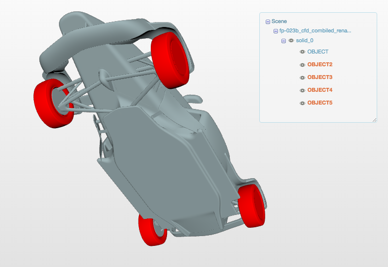
2.1 Export solid models as “ASCII” STL format files
Exporting solid models as “ASCII” STL files for each other.
2.2 Change the names of solid to
Names of solid may be the same for the each exported files and solids of the same name are recognized as a single solid.
In order to be recognized as separate solids you need to change these solid names for each.
Change the name of solid in the each ASCII STL files using text editor from like ..
solid OBJECT
...
endsolid OBJECT
to like …
solid OBJECT2
...
endsolid OBJECT2
2.3 Combine ASCII STL files using cat command
I execute the cat command on macOS. Linux may be the same.
I do not know that kind of command on Windows.
Thanks a lot yosuke ! Your post was quite detailed and very informative. I will test these methods on my model and let you know if its solves my issue. Cheers.
Hi @yosukegb4
Out of curiosity, is there any way I can split my background mesh box ? Like say my inlet face (need that to define two inlet phases)?. The only way I can import my model with an external domain is by using step or iges file formats but my surfaces always seem to faceted which leads to problems in meshing. STL format allows me to import my model as a single face alone, so I am unable to import an stl with an external domain. @dheiny I had a look at this discussion Collaborative simulation project? Multiphase flow around a boat hull - #45 by quequen and I am facing a similar problem. Is there any tool which allows me to combine these multiple facets into a single NURBS surface ?
STEP seems to be more convenient in your simulation.
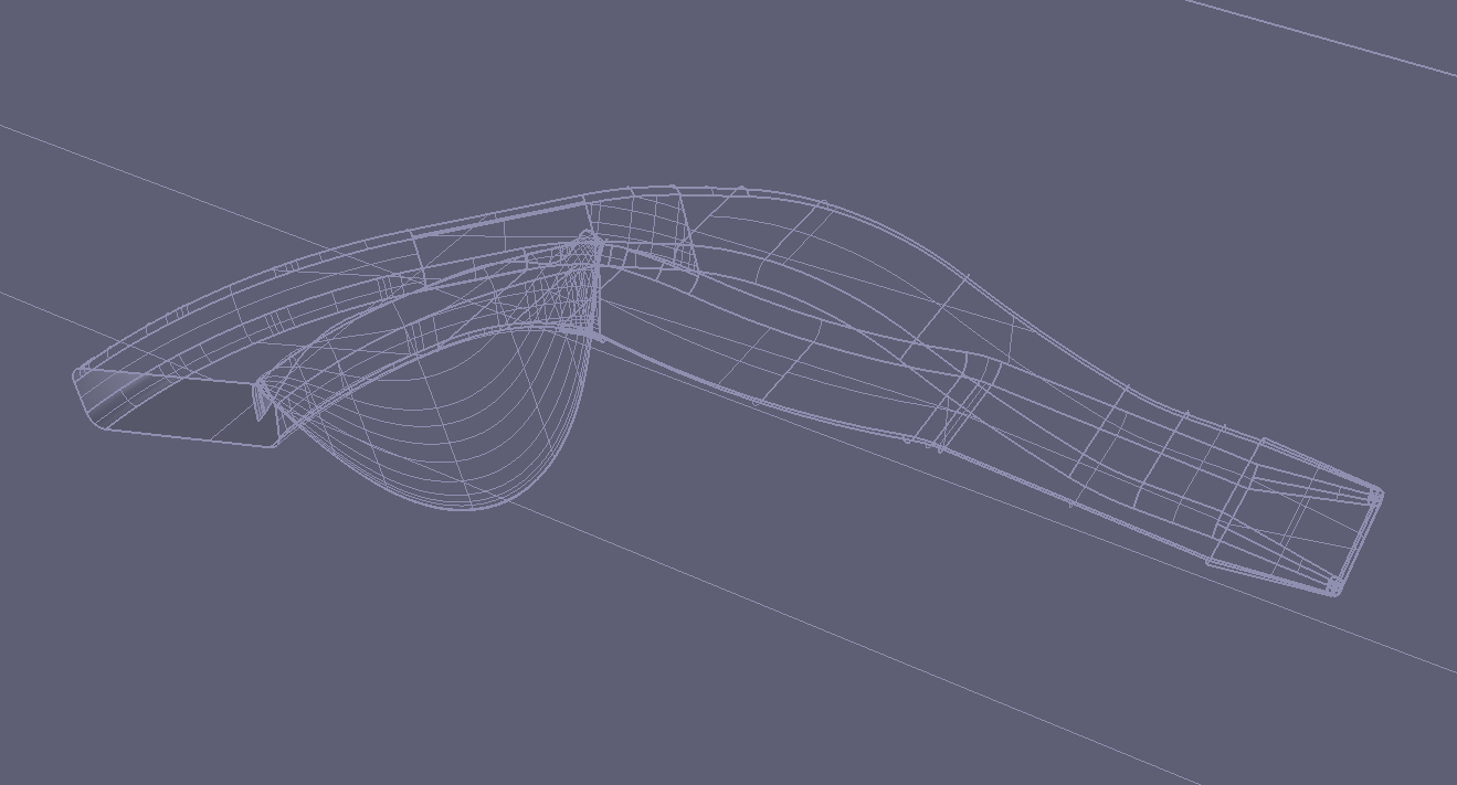
I downloaded STP file “SimscaleMod.stp” from your project and open it on Rhinoceros.
But it shows a wrong fillet surface as the picture in below.
Although there is a possibility of data conversion problem in Rhinoceros,
there is also a possibility of a defect in the fillet surface of your CAD model.
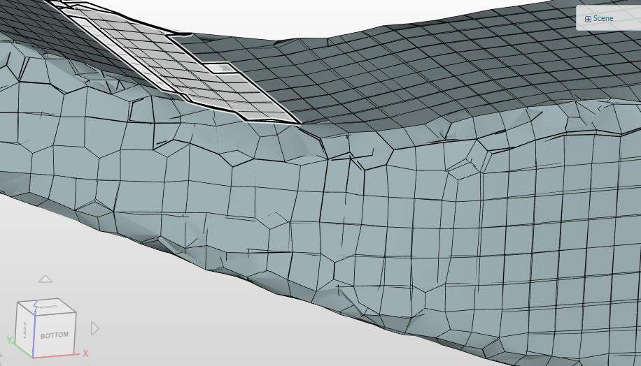
Generally, when there is some wrong surface in a model,
the mesher makes duplicated mesh like in your mesh.
I don’t know the reason well but it seems to have failed to determine the correct material area.
If it is possible, how about trying a model in STP file without fillet surfaces?
I completely revamped my geometry from the scratch and now I have a better looking model without any tessellated surfaces but I am having trouble with meshing. I get an error saying the mesh operation has failed. I checked the log and I dont see anything abnormal or any error . Can you have a look at my project and see if there is anything I missed. https://www.simscale.com/workbench/?pid=4808040960984650438#tab_0-0
Cheers.
Hi @cecil_pabbathi there was an issue detected on our end.
The problem is localized and a fix is already in testing. It should be released within a couple of hours.
I will let you know once it is completed.