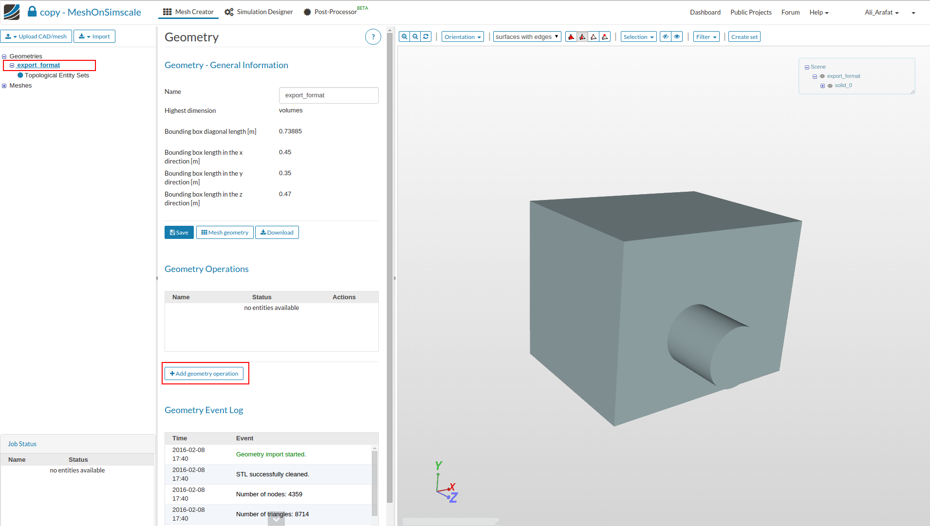
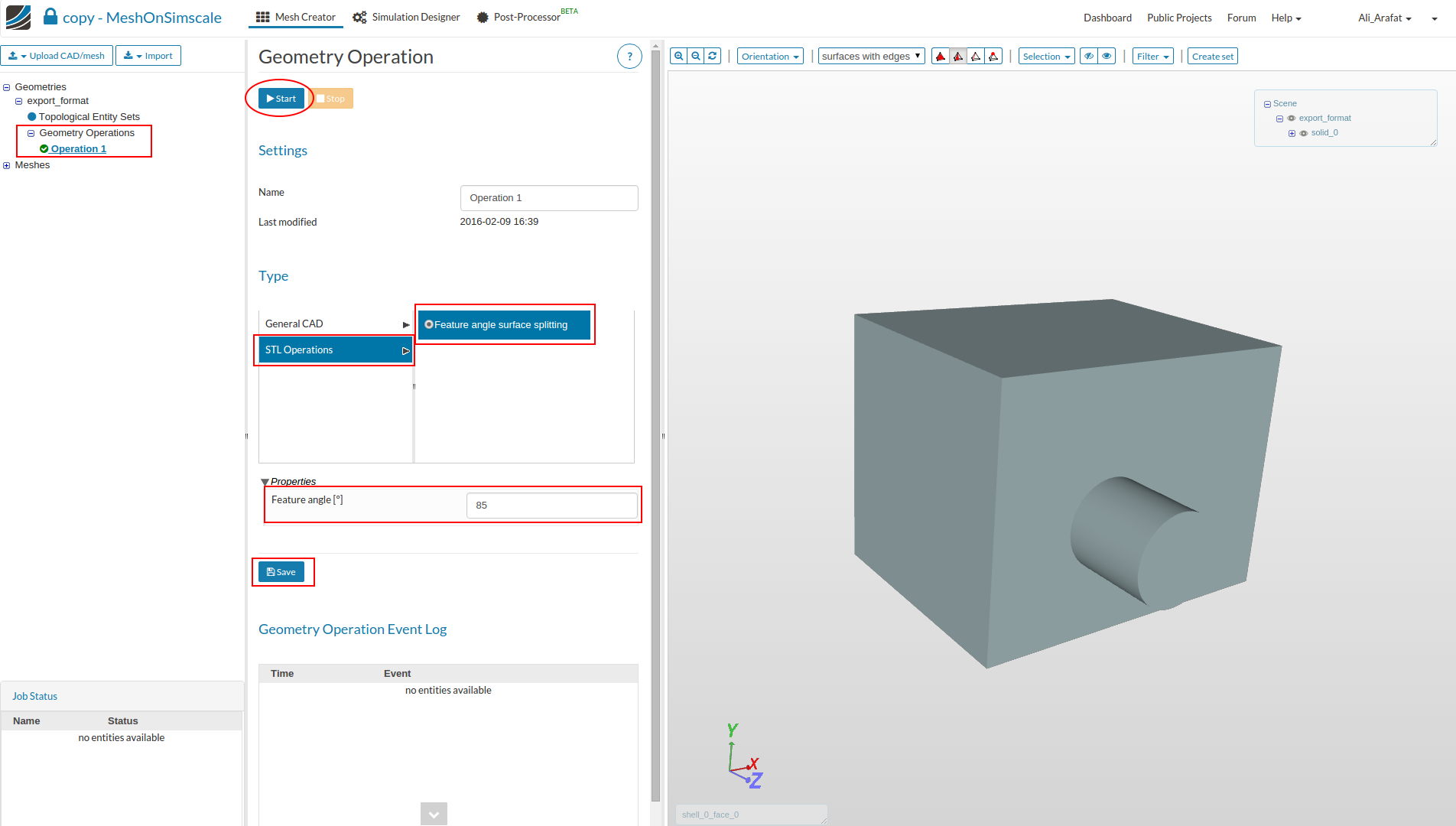
As a number of users experience this with STL files. Here’s how to apply a geometry split operation to create multiple faces for a STL CAD file that can later be used as inlet , outlet etc.
@Ali_Arafat
Thanks for sharing this instruction.
Is it possible to split an Entity Set (face set) in two face sets? This is needed for example when setting multiphase flow (to set up boundary condition for inlet).
Hi @Zoran, I don’t believe this is possible at the moment, could you do that in your CAD tool and then re-upload to SimScale? I hope the project is going well!
Hi,
can you tell me which CAD programs are able to split the faces similar to your online-tool? It seems to me that SolidWorks is not able to do so, at least I did not find any helpful sites on the internet…
Hi @BenLewis
It seems to me that it is not what I am looking for:
I want to be able to set different boundary conditions on different parts of a car, e.g. the wheels should be rotating. When using the splitting-tool I am able to do so but I get around 600 faces and the topological entity sets I set up in the geometry area are not transferred to the meshing area and the sets I set up in the meshing area are also not stored within the mesh so I have to set them up again for the simulation. Since I just want a small number of parts meshed finer and some of them with different boundary conditions it were easier if I could do the splitting process before uploading the part so I only have to cope with ~10 face sets instead of 600.
When I use the Split Line command on the part file I get error messages because I am trying to split e.g. the faces of the wishbone from the wheel but the faces are already separated so it cannot do anything.
When I open the stl export of the part the Split Line command is not available to split the now connected surfaces from each other so it does not seem to work.
The step file does not work at all for the meshing process…
sorry I can’t help you out here. I’m only familiar with the FEA side of SimScale and I only use STEP files. Hopefully someone else can point you in the right direction.
It is unclear to me - Is the original format an STL file (i.e. triangulated surface) or STP (solid body)? You should be using STP, not STL, and if the STP isn’t meshing, then you should troubleshoot in Solidworks. The split operation (whether you’re splitting parts or surfaces), should work on a STP file, unless there are geometry issues.
If you are trying to split a STL file in Solidworks, that won’t work. The split operation only works for solid geometry, and an STL file is a triangulated surface mesh, which is why I never recommend using an STL file for analysis. STL is meant for 3D printing, not FEA/CFD analysis, and is typically too coarse, but there are work arounds if an STL is all you have.
Please provide screenshots if you can. Even better, share the geo.
I always got problems when I used the step export which do not appear when I use the stl export and since the original snappy hex mesh algorithm uses stl files too I don’t think it is the worst idea to do so…
The only remaining problem I have is that I am not able to create a mesh with two mirrored halves of the car. I want to do this to do a simulation with an angular flow.
@L3br4nd - If you have problems with the STP export, then you have problems with your geometry. Just because STL “works” doesn’t mean it’s reliable. You need to troubleshoot UPSTREAM data (i.e. native CAD), not downstream. This advice is based on years of experience. Unfortunately, there’s not much help to give without looking at the geo. My original offer to review your CAD still stands…
What you are looking for is a colored STL, which basically consists in assigning a different color/ID to groups of faces so they are grouped together; the actual name depends on the software you are using. If I recall correctly, you can do that with CAESES, which offers a free to use license.
Just have a look at the project I forked; there I coloured your STL:
AFAIK, any finite volume CFD software will tessellate the surface; thus the advantage of using native CAD is that the tessellation process will snap to the geometry no matter what surface mesh resolution you are using. You can circumvent that issue by using enough curvature resolution when generating the STL.
mine crashes out every time i do it without any error log, any ideas? its a single internal flow mesh made in blender and converted to non binary in meshlab, edge splitting in thouse doesnt work either
@pfernandez Sorry for reopening such an old thread, but I am facing a problem that is strongly related to your comment, so I think you may really help me.
I am trying to split my rear wing into 6 different surfaces (2 endplates + 4 flaps). The native format is .SLDPRT, which has been then exported as an .STL. I have tried the following possible solutions:
Splitting the .STL (of the whole car) in SimScale: since the whole car that I want to simulate must be a single file, performing the splitting operation leads to more than 200 surfaces that then I have to group into topological sets… Not affordable.
Splitting the .STL of the rear wing in CAESES: the .STL exporting format does not work in SImScale (I get always an error when uploading the file). I have tried all the different .STL exporting possibilities that CAESES offers, none of them seems to work. Maybe I am not doing things properly, although I think it is simple: just split by angle, assign colours and export. In fact the exported file seems to be ok when analysed in the text editor, but it just does not work.
Splitting the .SLDPRT of the rear wing in SolidWorks: this basically implies using the “Split” feature in order to manually separate all the parts. It is possible, but again is takes tooo much time -and it is directly not possible if the geometry gains some complexity-.
So my question is basically the following: how did you manage to create those different “shells” in that project, or how did the people that carried out the FSAE homeworks split the wings into their elemental parts?
It’s been a long time since I do not use CAESES so I can not tell about the specifics of that software; but make sure that you are exporting the STL as an ASCII file —that is, make sure that you can view its contents in any text editor.
If that doesn’t work, another workaround could be to export each part as a standalone STL file. You’ll see that each file contain something like:
You can then just merge all files into a single file; in any GNU/Linux distribution it is just cat part1.stl part2.stl ... > whole.stl. You’ll end with something like:
solid
    ....
endsolid
solid
    ....
endsolid
If the software doesn’t name the patches during export, you could do it just like:
Yes, I can confirm it is being exported as ASCII. In afct, what drives me crazy is that, apparently, the format of the file is like the one you describe, so I do not understand why SimScale uploading fails (maybe geometries are not closed after splitting os something like that…).
Anyway, following a similar approach to the one you explain belo (using a merger) it is working, so the problem is more or less solved. Thank you for your help.
PD: Is it necessary to include the same after the word ‘endsolid’? I have carried out several simulations without including it and no problem has arosen…