Use of Bounding Box Layer , Y+ layer, boundary layer

Hi Everyone,

I’m trying to create the Y+ layers over the bounding box in Ymin Direction. So here’s my approach that I followed

So I’ve created a Bounding box where Xmin is -15 and Xmax = 15, Ymin 0 and Ymax=0.5 (All dimensions are in m)
I’ve calculated the wall distance by considering the boundary layer length = 30 m (Overall X is 30 m ). for Y+ I’ve considered 100 and from here I’ve calculated the estimated wall distance which is 0.005164.
#layers=5
ER= 1.3
The thickness of the final layer=0.01479
Min overall layer thickness =0.04

In the refinement, I’ve selected the Bounding box layer addition. and selected Ymin Bounding box face. and added all the Y+ related values which are listed above.

I failed to generate layers over the bounding box.
So I have following questions

  1. The Boundary Layer length which I selected is it right? My bounding box is overall 30m in X-direction hence the overall length is the single layer would be 30m. therefore I’ve selected this value while calculating my wall distance

2)Where did I go wrong that my layer generation failed?

Please do let me know if you need additional information. And It would be great if you all can help me to resolve this issue.

1 Like

Hi @sumedhsurve!

Tagging our PowerUsers @Get_Barried & @DaleKramer here who might help you out with that.

Best,

Jousef

I am not totally sure about what results you expect but I copied your project and made some layers for you.

Here is my copy with layers. I will leave that for a few days and then erase the project.

First, I assume you want an external mesh if you are layering the Bounding Box.

With that assumption I did this:

  1. Made your Background Mesh Box ~1 m larger than your geometry all around. This is not a realistic way to size wall spacing away from the geometry!!! That is a whole other topic which I have not got a good handle on yet, but for this simple layering test it will do.
  2. Changed your Number of cells in x,y,z directions to maintain approximately square cells on the Background Mesh Box
  3. Moved your Material Point to a location outside of your Geometry.

But then the layers on the ‘Bottom’ face of the Background Mesh Box still refused to appear.

So, I used some methods of this technique to ‘force’ them to appear.

I iterated that process and found progressively that 3 parameters needed to be relaxed until I got 100% layering.

First, ‘Min normalized cell determinant’ from 0.001 to 0.0001.
Then, ‘Min Face weight’ from 0.02 to 0.002.
Then, ‘Min volume ratio between neighbouring cells’ from 0.01 to 0.001.

BUT, even though the thin layers appeared, I do not think you should use them that way.

You should at least change your Background Mesh Box grid size so that you can put ‘Min volume ratio between neighbouring cells’ back to 0.01.

Then you need to determine what affect the other 2 parameter changes would have on the accuracy of any simulations you do with the mesh. If the affect would be unacceptable, then you should figure out ways to retain the layering while putting those values back to their default values. For advice on this step, you need someone with more knowledge than I to step in here :wink:

Here is a clip at x=10 of the layers:

Also, I am not sure if 30m is the correct reference length for your layer creation, perhaps someone else can help on that…

Dale

3 Likes

Hi @DaleKramer , Thank you very much I’m trying to access that project which you created, but iIm getting errors.

Sorry, forgot to make it public, should work now.

Oh, and I forgot to mention that since you have left ‘Use relative size for layers?’ at the default value of True, you will not obtain your desired final layer thickness of 0.01479m.

The final layer thickness will be a ratio of the thickness of the ‘further out’ cell next to the thickest layer that gets added. My projects Level 0 grid size gave a final layer thickness of ~0.00268m.

This was very confusing for me too as the parameter description for relative layering is ‘Thickness of the final layer [-] or [m]’, which to me implies that I can put in either a ratio or a thickness and the code would simply know what I mean :wink:

2 Likes

@DaleKramer @jousefm First of all sorry for the late response, some important stuff came across.

Just to give you more information about this project so Here I was trying to create the layers over the surface of that trapezoidal shape.
Few things that I’ve noticed

  1. Its bit difficult to create the layer over the top if you have STL geometry file uploaded

  2. Hence I’ve used STL split option so that I can select surface accordingly, But here you can use the Inflate boundary layer option.

(FYI, I’m trying to select the bottom surface of the geometry as I want to add the roughness over there, That’s the reason I’m creating the boundary layers over there, So I can estimate what will be the Friction Reynolds number)

  1. if you have an STL surface, As It’s a bit difficult to detect the surface, I thought to use Bound box layer option with Y min. So without performing the STL Split operation, I can create the Y+ layers.

  2. As you mentioned increase the Bounding box by 1 m so in my case this is not gonna help me. As I want the layer on the horizontal surface of that trapezoidal section.

5)Now, what I tried to do I’ve run STL split operation and used Inflate boundary layer, In meshing log a single layer has been generated but it’s too low. And I saw the illegal faces which are somewhere around 18.

6)As I don’t have profound knowledge in OpenFOAM hence I’m not much aware how the meshing solver works but I’ve noticed few things. That for my mesh operation some illegal faces have been detected.

7)So Ultimately I’m trying to reduce this detected face to 0.( Which I think this way I can create the layers ). In order to do that, of course, I need to play with the Mesh settings and which I’m not good at.

So Here is the Question I have

A) How should I create the layers on that Trapezoidal Section with STL surface or be more precise by using bounding box layer addition method? (Again I want the layers to be generated over the horizontal surface of that trapezoidal Section so I can see how the roughness behaves with different Y+).

B) If the (A ) is not possible then with the Inflate boundary layer option How should I reduce the Illegal faces?

Basically, I just want that layer to be generated over the horizontal surface of that section So I can play with Y+.

Let me know if you need any additional information

Sumedh

You are using the wrong refinement to add layers to a geometry face. Use this:
Layers1

@DaleKramer Can you tell me how did you estimate this value under which Y+ it comes.

Do you mean how can I ensure that the layers made using a ratio of, say 0.3, in a ‘relative’ layering scenario will match my desired Y+ value ?

@DaleKramer, I mean I can still calculate Y+for this 0.3 as we have all the values there.

My Question is specific how did you know this thickness will work for this case.

What is the logic behind this ?

And By the way It worked but I need to know how do you know that this value is perfect. What is the logic behind this

Actually this 0.3 is a ratio of final layer thickness to the dimension of the first cell next to the surface, from that you can figure out how to calculate the final layer thickness in meters. To obtain a good y+ layering I recommend to use a surface refinement with max and min levels set to the same value. like this:
Layers4

That grid size should be approximately equal to (but greater than) the final layer thickness which you desire. Then you can determine the proper ratio to use based on that grid size. Say you want a final layer of 0.002 meters. Say Level 8 grid is 0.005 meters (a Level 0 grid of 1.28 meters), then you use thickness of final layer ratio of 0.4.

If you need further refinements you can do a feature refinement at level 9 like this to make sure that your surface/face intersections are sharp;
Layers3

And a further level of refinement on very small surfaces like blunt wing trailing edges like this:
Layers2

That info was very hard for me to learn as there is no guidance on detailed use of relative layering anywhere I looked.

To make sure that your final desired Y+ is achieved, you need to use the expansion ratio iteratively, by the number of layers you desire, on that final layer thickness (in meters) until you determine the first layer thickness near the surface which should match the ‘estimated wall distance’ (EWD) output of the online y+ calculator. Vary your final layer thickness RATIO accordingly so that your first layer matches EWD where those Level 8 cells were created on the faces. If you have to go below 0.2 or so with that ratio, then I would say that you should do your ALL faces surface refinement one level finer.

I am not sure of the relative layer settings that were in the project, I deleted that project yesterday. I just took these screen captures from another project of mine.

P.S. Make sure to use a ‘square’ grid on all faces of your background mesh box for the above recommendations to be accurate. Also, make sure that your background mesh box is large enough so that its walls do not affect the flow around the geometry (you can optimize these box sizes later but a good place to start is at least 4Xgeomtery dimension in each axis). And likely you would need a cartesian refinement box (sized about 2Xgeometry bounding box dimensions) around your geometry refined to about level 5 if you use the 1.28 meter level 0 grid that I have grown to like)

You can eventually get layering yPlus mapping like this where yPlus =50 was desired:
yPlus50

2 Likes

Hi, I performed the similar Simulation and yes you are right. that In order to create the layers (“If the Relative Layering is True”) But can you explain me more in details.

So I performed two different simulations just to see what are the effects of relative layering If I add the roughness over the surface.

The First Simulation I performed by considering the Y+= 300 and the the Relative Layer is False the Roughness I’ve added is 0.01 m.

In the second simulation, I performed the same but this time I’ve used Relative layering as True and Followed the similar method which you explain by taking the ratio for the final layer thickness and using the grid level accordingly by using the Feature refinement. and It worked.

So FOr both the cases I’ve obtained the similar results in terms of velocity and Pressure Head. Ultimately I was trying to see the effects of roughness with Different Y+.

@jousefm @DaleKramer My Question to you is

  1. Can you please explain to me how the Relative Layer if False how it worked exactly?

2)As you mentioned take the ratio by comparing it with the refinement level and add that RATIO VALUE AS YOUR Final Layer thickness. I want to know how It’s’ working what is the Logic behind this.

  1. How does the Roughness Affect the Y+? I’ve heard that In order to detect the Roughness your First Layer thickness has to be twice or thrice More that the Roughness Height.

But the First Layer thickness actually depends on Y+ and the Y+ is depend on Shear velocity and Friction Reynolds number Hence to obtain the perfect wall distance You need to know Three main Inputs
Boundary Layer Length
FreeStream Velocity
Kin Viscosity

My case, It’s difficult to obtain the First Layer thickness Twice more than the Roughness Height.

Hence I thought to add layers by using the Relative Layer sizing as True, SO In this way, I can add the Final Lyare thickness by using the refinement level. and From reverse calculation, I can see what would be the appropriate First Layer thickness which is twice more than 0.01 m, so here 0.01 is my Roughness Height.

I have found that relative layering only helps if the size of the surface grid varies, and then only if it varies within a small range (one or two refinement levels). If your surface grids are the same over the whole surface or there is only a small percentage of surface cells that vary in size, then it is likely that there will not be much different in the results since the layers will have disappeared rather than got thinner over just a small percent of the surface (just what I have noticed).

It just lets you maintain layering as the surface grids change size rather than disappearing completely in those areas (again just what I have seen).

I have no experience with roughness, I want surfaces as smooth as a sailplane wing :wink:. Perhaps someone else has suggestions here…

Dale

@DaleKramer Thank you very much. I’ve created other topic for the roughness. Really appreciate for sharing your valuable knowledge with me.

Just last question.
Can you tell me on the meshing log at the bottom where we see the Layers Table so can you tell me what is mean by overall and the percentage in that table?

the overall meaning means the length of all layers (Summation of all layers)?
and the Percentage depends on the overall min layer thickness.

Sumedh

I have not quite been able to figure out how the columns are figured out.

To get a feel for the overall % layering of a mesh, I use a weighted average by averaging the product of the faces times the Thickness %.

You might find it interesting to find your ‘Perfect layering’ table a ways up higher in the meshing log (sometimes it appears even before the last 1500 lines that you can see after the meshing is done, if that is the case you have to capture it by meshing again and watching the log in real time).

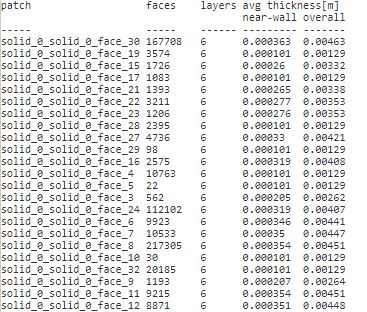
Here is the Perfect layering of a relatively layered mesh of mine:

Perfect

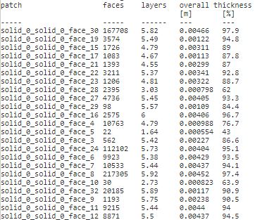
And the Actual layering that is left at the end of the log:

Actual

If you really want to maintain the perfect layering (at a cost of a lower quality mesh as far as the solver would like to see) I would again suggest following this procedure which I have developed.

Dale