Hello,
I tried simulating a battery for identifying temperature rise, the battery has no dedicated cooling system, it relies on its metal case for cooling, initially I used CHT V1 with very very small inlet velocity of 1e-4 m/s and a default outlet pressure, I tried to capture a natural convection scenario with these setting. The temperature rise was 35°C. Then I used CHT V2 with only natural convection and the temperature rise went to 829°C which is very high, I want to know what went wrong, In physical condition the temperature rise is around 40°C and with inlet-outlet boundary condition temperature is 35°C but with natural convection BC temperature reaches 829°C which seems impossible. Please help!
Hi ankushsharma23,
thanks for reaching out to us here in the forum,
From what I can see ist that first I would recommend you to create a larger volume for the air. right now any air that rises to the top just quickly exits the fluid domain. You can check this by having a look at the flow rate at each face of the air volume.
For this to work efficiently you most liklöy will have to reduce the mesh. But you can do this by using the symmetry of your battery.
Symmetry of the object:
Please let us know if you have any questions and if this helped.
Best regards Sebastian
Hello Sebastian, thanks for your reply, I will surely try these recommendations and get back to you.
Hi Sebastian, In natural convection, as you said, the mesh elements will increase and would take a lot of time to solve, even with symmetry, I would like to know is there any other way I can create a natural convection scenario by maybe using the inlet velocity-outlet pressure BCs as I did in the first run, will it be feasible?
Hi ankushsharma23,
first please have a look at this tutorial and see how to apply the symmetry boundary condition correctly.
You can also see how the natural convection boundary condition is applied here.
And sure there are other ways to generate a natural convection BC, but this wouldn’t decrease the number of cells needed since you need the size of the fluid volume to have the fluid field fully developed.
And your first definition of the BC was more like forced convection within a box scenario than natural conversation. And with 4 Mio Cell Simulation Time around 2.5 hours are expected.
I’d like to add something: Are you using a manual relaxation type (numerics)?
The solution is clearly wrong (had some divergence) in the initial iterations and this is most likely to the very large relaxation values you set:
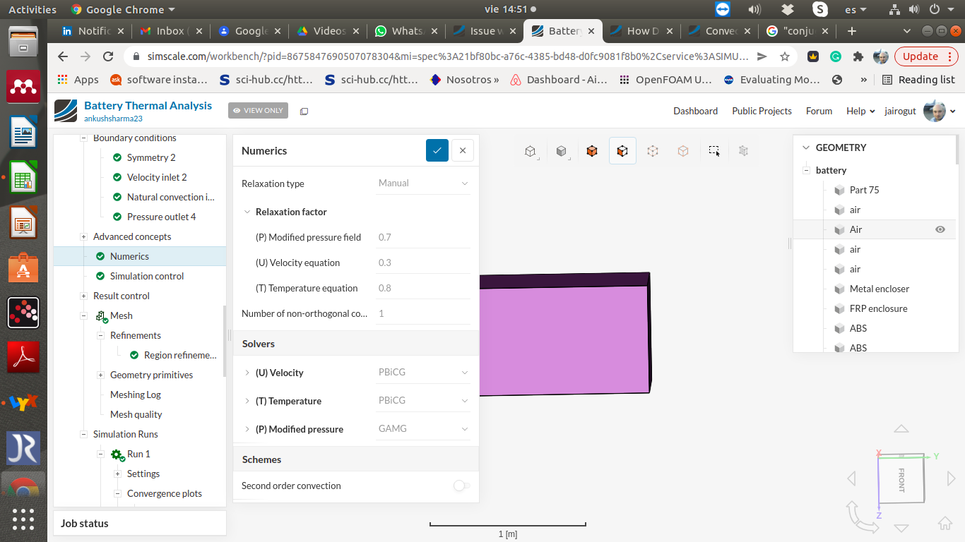
I don’t remember if you can set these values automatically for CHT2 in SimScale but if you are using manual relaxation, set them to something like 0.01, 0.02, 0.02. For natural convection, the solver is extremely sensitive to these relaxation values. I do not know the form of the transport equations for CHT2.0 but I suppose that if a strong coupling of the energy equation between solids and gases is used, the solver really requires low values for the relaxation factors. Also, initialize the solution with the correct velocity inside the whole domain (the same one set for the inlet boundary).
Let me know what happens.
Hi I used the default numeric settings, I didn’t altered any relaxation factor. I’ve input the recommended values, I got a warning that overall sum of pressure, velocity and temperature must be 0.9 to 1.1, however I went ahead with the values and will get back to you with the results.
I would like to know what other ways I can create a natural convection scenario, initially I used inlet air velocity of 1e-4 m/s so I thought it will be a good representation for natural convection, currently I setup the natural convection boundary condition as suggested in the tutorial along with relaxation values suggested by @jairogut , will post the results as soon as analysis is finished
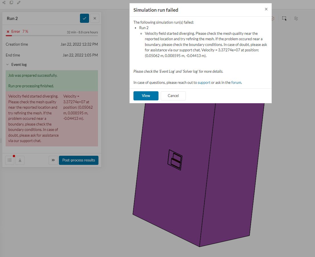
I tried using the recommended settings, but I’m getting an error.
The simulation previously ran on the same size so I think maybe this error is because of altering the relaxation values since I was also getting a warning related to the sum of these relaxation factors.
Yeah, it may be. I’m afraid I do not use SimScale much but OpenFOAM (although they are almost the same). I know SimScale has some further code enhancements that control such residuals, therefore my advice was not that good (I thought you had set manual residuals). If your simulation was working in CHT1 why are you using now CHT2? I have modelled natural convection with natural convection inlet/outlet BC’s, but I am not sure if they are available in your solver: SimScale. These BC’s allow free flow movement (buoyant flow to leave the domain and “cold” flow to enter the domain).
Ok, there are a number of things I think we can do.
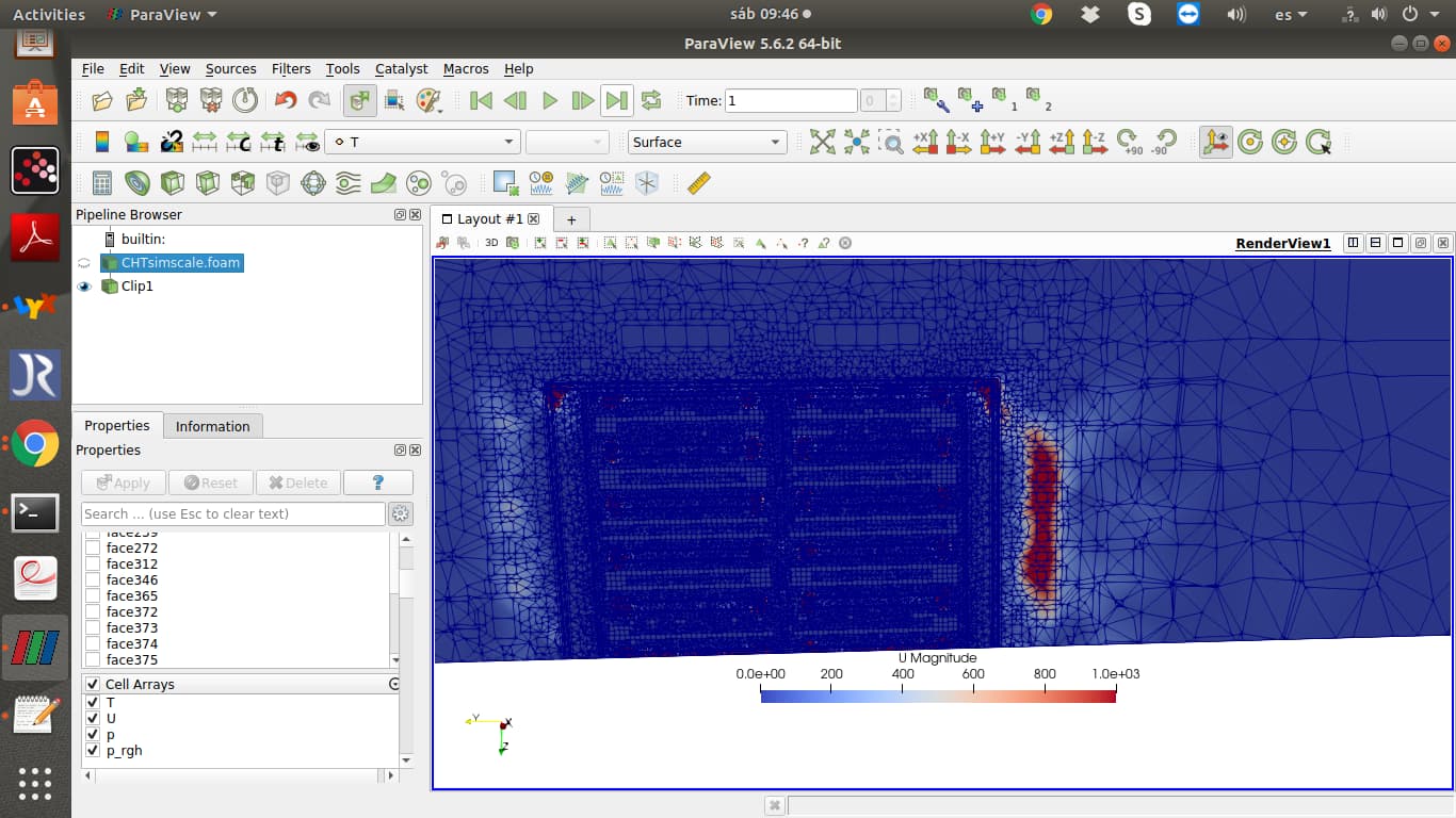
- I suggest working with parametric Hex-based mesh and manually setting cell levels per zone. If not, check mesh quality and control it. I will show a picture where the case is diverging below.
- I also suggest working first in a simplified test case. This test case will represent a small section of your battery cooling pack and will have a much-reduced number of elements.
- Follow the advice given above by @SBlock
Is the grid in those regions fine enough? (@SBlock asked you about that issue). Remember that if you use the parametric-hex mesh you can define where the grid needs to be fine and where it does not. Therefore your grid will not need to be that fine. Again start with a test case (which will converge quickly) and set the natural convection BC’s.
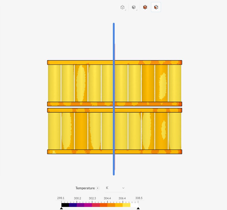
In the case 2 (with fixed relaxation values) the solver informed us that velocity is diverging at “Velocity = 3.37274e+07 at position: (0.05062 m, 0.008595 m, -0.04413 m).” This is clearly around the batteries. Case 1 and 3 do not diverge as SimScale automatically controls relaxation values but they clearly had huge non-physical surges in the velocity field (trying to diverge).
For your CHT2 case 2, velocity clearly diverges in these regions:
Best regards,
Jairo
I initially used CHT1 with a very small inlet velocity of 1e-4 m/s and atmosphere outlet pressure to simulate a natural convection scenario also the domain was small as you can see in the project, the results were close to the real life temperature, simulation showed 35°C and physically temperature reaches upto 40°C, the max flow velocity in this case was 0.05 m/s so I thought this might be a good representation of natural convection. I then read about the natural convection boundary condition and CHT2 on simscale and then I ran the simulation with natural boundary condition hoping the results will be more close to real life, I used the same domain and mesh count but the temperature reached to astonishing 830°C, since then I have tried increasing the flow domain, also used the symmetry BC and natural BC as suggested in tutorials, however the temperature rise still went upto 720°C.
As suggested by you, I’ll reduce the mesh size, will use refinement regions I cannot change the algorithm to hex-dominant, this option is grayed out and only uses standard algorithm, will post the results.
Hi i think @jairogut gave you some pretty good help.
I would suggest you is to change the top face above your Battery to a pressure outlet face since we know that the air will have to exit there.
Also please have a look at the region refinement page:
Also how much power does the battery pack provide?
Just want to make clear that this is not a problem. Currently, 1.9W is given per Cell. So121W Total.
Also, you should be able to switch to the hex parametric mesh.
you can switch it here:
You can also create multiple meshes when you just extend the current mesh and click on create a new mesh to keep the old mesh for reference.
I hope that helps.
Best regards Sebastian