The objective of my project is to study the effect of dimples on a golf ball in reducing drag and to provide a comparison between a golf ball and a normal smooth ball of similar dimensions. Since a golf ball reaches speeds of circa 100 m/s, I have defined a speed of 50 m/s (half the actual) in the boundary conditions so as to not push SimScale to its limits of incompressible flow simulation (0.3 Mach or 100 m/s).
I have tried to create a mesh as suggested in the ‘external aerodynamics over vehicle’ tutorial. Link is here.
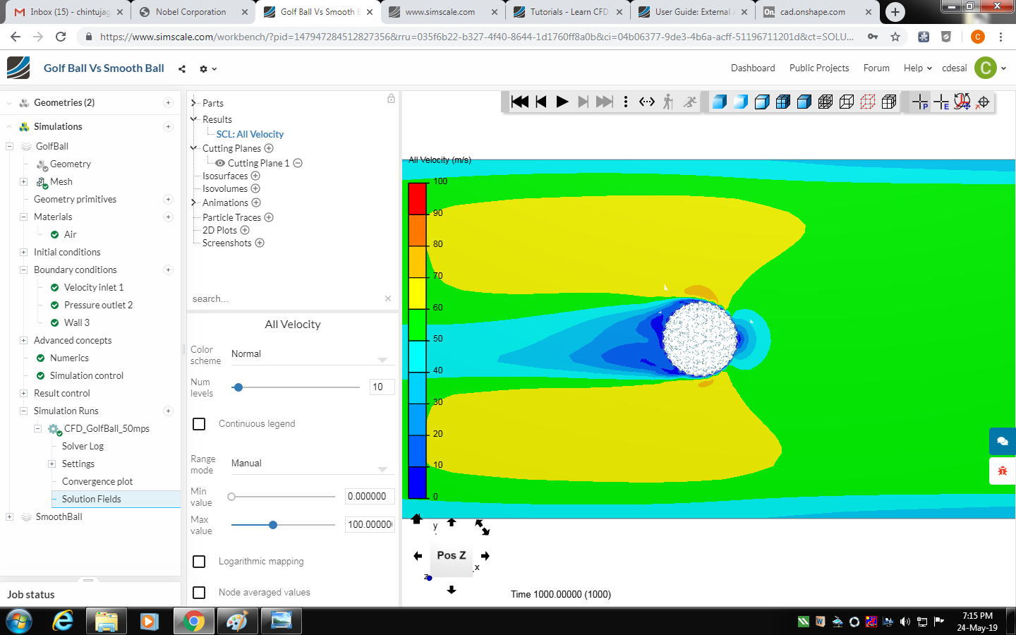
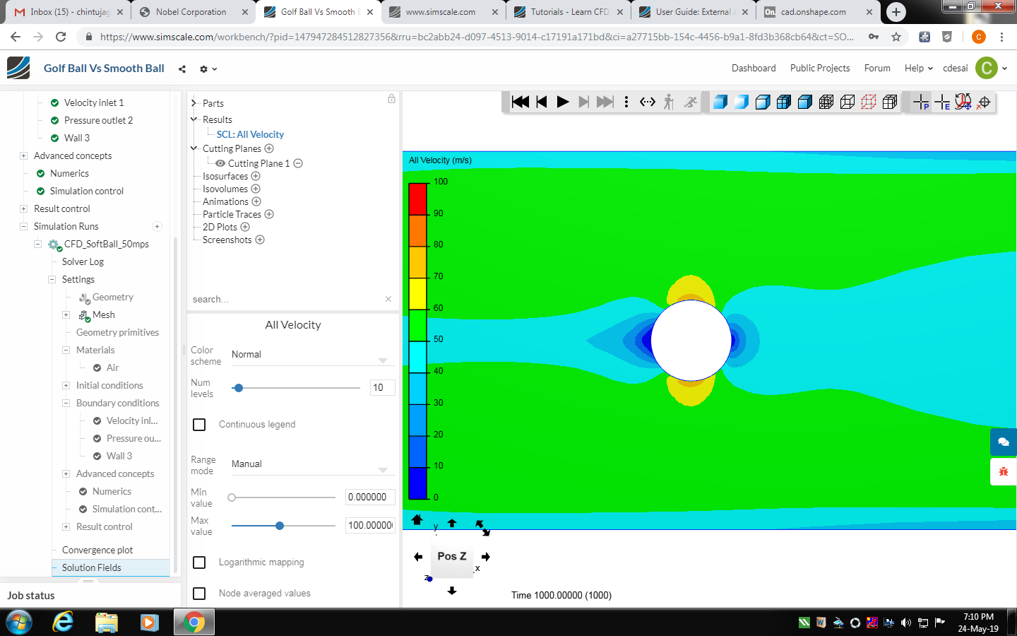
However, I’m not getting the expected results with the simulations. According to the results, the smooth ball is the one generating less vortices at the back, effectively suffering less drag.
You can find the link to my project ‘Golf Ball Vs Smooth Ball’ here.
Please suggest some pointers which could improve my simulation and help me get expected results.
Thanks so much in advance.
P.S. - I’m new to the SimScale platform and pursuing CFD analysis as a hobby. I got into it through my interest in fixed-wing UAVs which got me interested in aerodynamics. I’m trying a few projects to learn the SimScale environment. This is basically the first time I’m trying a CFD software. Please be kind.
Absolutely no problem - a very warm welcome from our side Make sure to browse our tutorials, learning videos as well as public projects to learn as much as possible. In your freetime you can have a look at our blog.
Regarding your setup I would use different boundary conditions (BCs) for the outer walls. Please use the slip boundary condition, the inlet and outlet are fine. Although the no-slip wall boundary condition will be enforced if you choose nothing for the ball I would still explicitly create a separate BC for the ball. You might also increase the size of the domain to exclude any influences from the boundaries to the flow field surrounding the ball.
Let me know if you have any questions. The @cfd_squad and I would be happy to help.
I have done everything as directed and should be ready with the results soon. I’m waiting with fingers crossed for the simulation to end.
However, there is one thing that has still got me confused. While setting up the velocity inlet boundary condition, the tutorial uses a negative velocity in the x direction (-63.7 m/s in case of the vehicle). Wouldn’t this mean that the air enters the boundary box from the face opposite to the face on which I defined the velocity inlet condition? Wouldn’t it then make the velocity inlet face effectively the velocity outlet face? I’m sorry to sound vague.
Meanwhile, I’m going through multiple public projects and tutorials to expand my knowledge about the domain. Hope to be included in the CFD_Squad someday. Haha.
Yes, that little hint about the coordinate system definition did the trick. I checked the little cube in the corner which signifies the xyz axes and figured why the inlet velocities are negative for certain projects.
Maybe it is not a problem associated with the simulation. As a golf ball moves it leaves a turbulent wake region where the airflow is agitated, resulting in lower pressure behind it. Boundary layer development varies significantly due to varying dimple geometry. Studies have shown the drag coefficient is strongly influenced by dimple depth ratio and surface roughness. Thus, the smooth ball may generate less vortices at the back if the dimples are not properly sized.
Because of this, field solutions, specially those close to the surface and in the wake are not accurate and hence your drag calculations are affected.
In addition, capturing the boundary layer requires special grid size conditions, which are related to the y+ value. Are you resolving or modelling the boundary layer? At first glance, your grid looks very very coarse around the dimples.