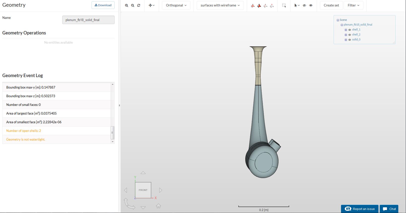
Hey everyone! I am having trouble meshing my geomtery. My cad seems to be water tight but meshing fails. I have attempted hex dom para and hex dom automatic.
My geometry is for internal flow i.e my cad is of the air inside the volume.
To understand the setup better i started working on a simple C D nozzle for simulations. m boundary conditions were 1atm inlet and 90kpa outlet.
tolerances are in order of e-5
end time is 500 secs and max run time is 100000 s .
i cant seem to run my simulation since it says max no of timesteps exceeded . could someone help me clear ot wheter the end time and max time should be same ?
my mesh in hex dom auto seems correct for all the faces except for the inlet face. i tried solving it by using parametric and surface refinment level 2 and 3 but as seen (in mesh 6) the inlet geometry is absorbed and everything is distorted. I have tried parametric on same CAD file before and it only disappears when i use a surface refinment.
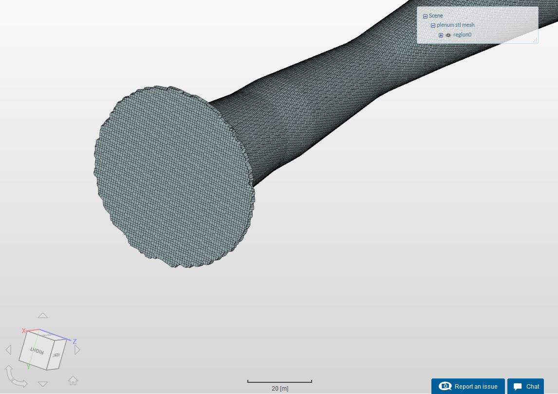
I was about to help you mesh on my end but I realize that your “plenum stl” may of the incorrect scale as it is currently over 300m long which compared to your “plenum step” geometry (about 0.3m) is obviously absurdly large.
Do rectify this issue and I will instead mesh your “plenum step” file to see if I can get something usable.
Hey ! is it fine if I use the STEP file? when i upload the .stl file it gets scaled 1000 times . i saved the same file in stl format but still it gets scaled
Hi. I think i need to refine that edge. im trying to iterate the feature refinement included angle so the solver detects the mesh. is this the right way?
While everything other parts of the geometry is fine, my attempts to obtain a proper mesh of the inlet has not been successful.
@jousefm Do you have any ideas on how to get a better definition at the inlet? I’ve tried higher refinement levels for that particular inlet and feature refinements as well but to no success. You can refer to the distorted mesh below.
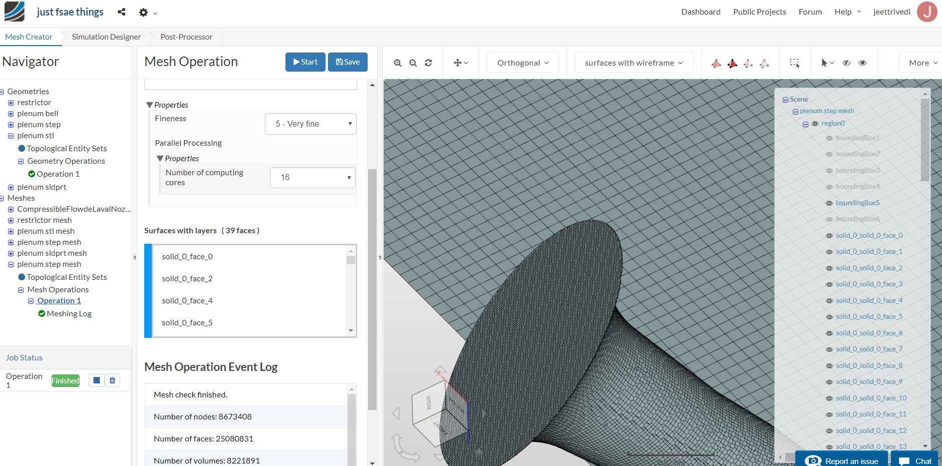
But I believe there might be some problem in the simulation. I did a Hex Dom Auto (level 5 ) and it meshes with the bounding box (I have kept only the rear face of box visible ). In my simulation, I do not need the box and just he faces of my actual solid.
Fantastic. Looks like the auto solver managed to solve the issue. I’ve been trying for the past few days playing around the meshing parameters in the hex-parametric meshing option but to no avail. At least you can try simulating now.
The box is by default and you can ignore it and perform the simulation as if the box isn’t there at all.
Hi @pfernandez, I lowered down this from a default of 1e-13 to 1e-15 then to 1e-20 and that didn’t really produce better results as far as I can see. Any other possible suggestions? The automatic mesher seems to be able to solve the issue albeit at the highest refinement level. Cheers for the input however!
@Get_Barried reducing min vol to -1e+30 turns this check off completely.
@jeettrivedi it looks like the mesher has meshed the wrong region, external region instead of internal. Try Hex-dominant parametric starting from one of Barry’s meshes and ensure the material point is within the geometry.
I ran a simulation with the new mesh. same problem. It always solves till the same amount of timesteps and give same values of residues before displaying an error
I’ve reviewed your simulation again and would like to add some additional comments:
You should split the geometry, because now it’s just a single surface. This is necessary if you want to specify inlet and outlet boundary conditions and also add prism-layers to the walls. You can use the STL splitting operation in SimScale.
You might want to align the outlets of the geometry with one of main Cartesian axes in order to get a better mesh definition at that boundary.
You should extrude the inlet in order to get a fully developed flow. As you have it now, when adding the bell you have a near perpendicular-to-the-flow wall facing the inlet. This way you are forcing a homogeneous flow, straight into a wall, which need to be deflected and this just calls for trouble. An even better solution —if you are simulating what seems to be an air intake— is to create an artificial plenum at the inlet with boundary conditions that of the freestream (have a look at the following video to get an idea).
Hi ! Thanks for the input! I shall make a CAD of it .
I have tried the splitting on stl but for some reason my geometery is scaled by 1000 times in stl file