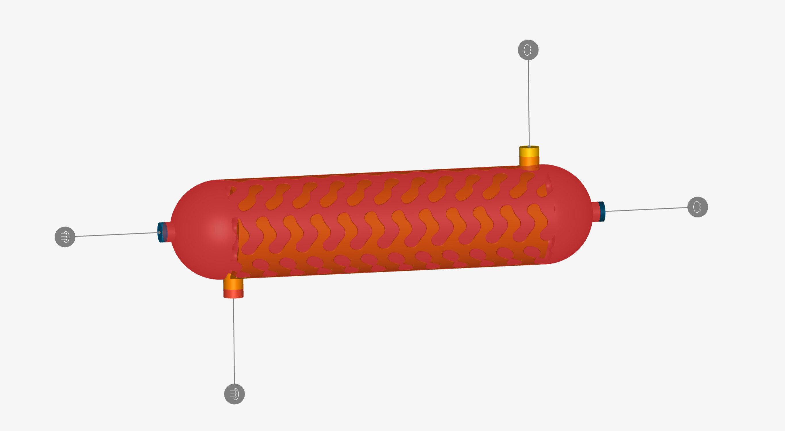
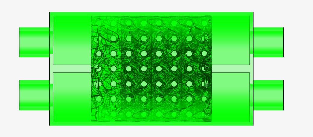
When scaling the heat exchanger to 500 mm length and small TPMS cell size,
the facet count is at approx. 10 mio facets.
(1 M shell, 4.5 M fluid bodies each).
What is the element limit ?
Import fails:
a)
*The archive contains .stl files which could not be imported as the number of triangles exceeds the maximum allowd. Please try to reduce complexity of the listed geometries in order to import them
b) The import of the model did not finish on time. Please try to upload the model again and disable some import options) Error code 42f37268
Import with a coarser mesh and all import options turned off is successful, but then the manual facet split problem persists.
Import with a coarser mehs and face split on import works, but generates a heat exchanger main body and 3 bodies consisting of one triangle each.
Boolean Union of these 4 bodies gives this error:
Union failed. Union operation could not be performed on … Search your model for gaps or try narrowing down your selection set if possible.
Is there a way to import the 3 bodies indepently and then merge in SimScale ?
Can I maybe import a fluid body volume and 2 fluid body surfaces independently and use the surfaces bodies for the BC ?
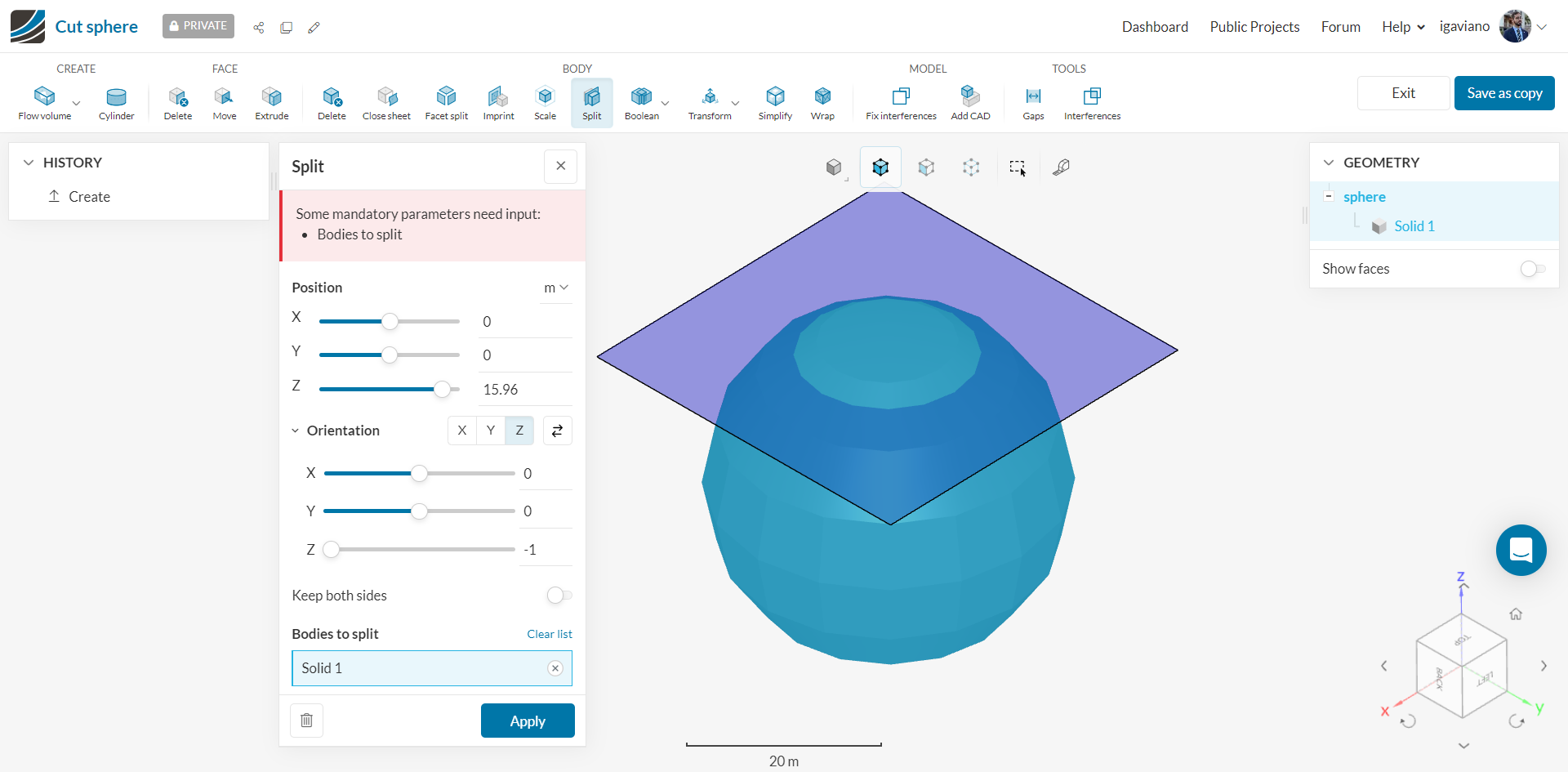
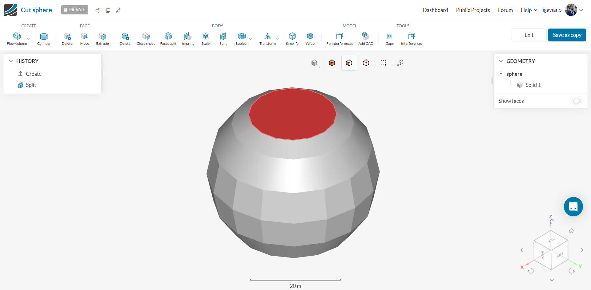
Hi, have you already tried to use the “Add CAD” tool in CAD mode?
On a side note, it’s very likely that you don’t need such a fine stl file to run this study. The IBM mesh is going to have much less resolution than what you have right now, so having such a fine surface mesh on the stl won’t really make much of a difference.
According to our CAD team, the limit number is 3e7 triangles (30M), but the timeout for the operation is 90 minutes.
They also provided further commentary that may help answer your question
which is:
It is possible to import each geometry separately and then use “Add CAD” function in CAD mode to merge them into one geometry. Performance could be a problem, but in theory it should work.
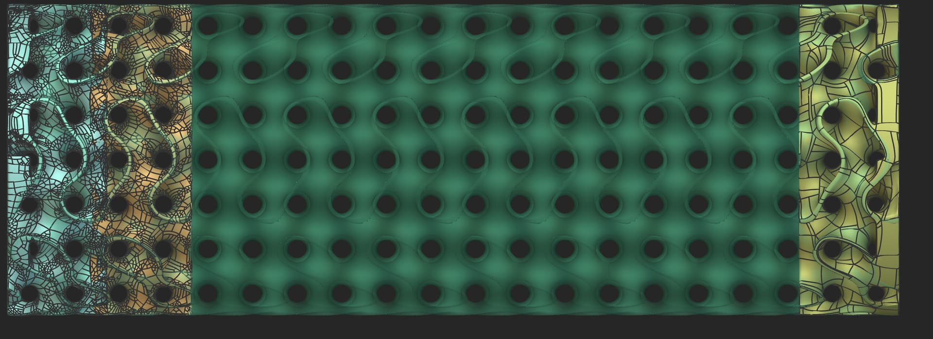
In general, handling of such huge and complex lattice geometries is not an easy task, especially regarding facet splitting. We do have some plans to support such complexities in the near future by: 1) doing manual facet split only for intake/exhaust, not for entire complex geometry. 2) Supporting directly nTop import. Both of the above can be expected to be supported in the near future.
I tried a different meshing approach with which I can generate smaller meshes.
When importing with facet splits on or off in both cases I have 44 volumes,
with 3 main volumes and 41 small volumes.
I tried Boolean Union to merge the small cells with the main body and the “Union” feature worked in cad mode, but it does not merge the solids in the geometry tree on the right side.
Do you have any idea why the “Boolean Union” does not give an error but doesnt really merge the volumes either ?
I cut of the inlet/outlet parts from the fluid volumes and uploaded all parts without import options
Then i manually applied facet split on the inlets/outlets.
Fluid water: for fluid bodies and the inlet/outlet bodies
Solids PP: for the shell
This gives the following error messages:
1 Found solid materials (PP) assigned to sheet bodies. Please remove these assignments.
2 The simulation contains only inlet boundary conditions for the fluid region Cold_IN.stl, which will most likely lead to global continuity errors. Please select an additional outlet boundary condition.
3 The simulation contains only outlet boundary conditions for the fluid region Hot_OUT.stl, which will most likely lead to global continuity errors. Please select an additional inlet boundary condition.
4 The simulation contains only outlet boundary conditions for the fluid region Cold_OUT.stl, which will most likely lead to global continuity errors. Please select an additional inlet boundary condition.
5 The simulation contains only inlet boundary conditions for the fluid region Hot_IN.stl, which will most likely lead to global continuity errors. Please select an additional outlet boundary condition.
6 The simulation contains only sheet bodies CAD geometries. Sheet bodies can only be used as caps to enclosed CAD volumes.
Looks like the inlet/outlet bodies are somewhat problematic ?
Any ideas how to set this up ?
2 to 5 - That’s probably due to the issues you mentioned concerning the division of the bodies, or maybe because they are sheet ones. You’d need to apply an inlet/outlet condition to the same body
6 - That’s again due to problem of you not having volumes. You won’t be able to simulate sheet bodies
I just wanted to reach out again to say that we had an idea that might help you: instead of enabling facet splitting, you could disable it and split the boundary condition faces manually, since they are simple inlets/outlets.
thank you for the idea with the split functionality. This might be a good solution compared to the automated faced split which might take long and wont work correctly sometimes.
I had repeatedly quality issues when importing the stl files, with different import options.
It seemed that upon import small elements with high aspect ratio or very small elements got lost and hence could not be recognised as solid bodies but only shells in SimScale.
I set up a new model in SolidWorks and imported this into ntop and only meshed the gyroid part, cut it in 2 end slices and a repeatable middle slice and converted these 3 parts to step files indepentendly.
In Solidworks after import I merged them together, and imported parasolid files into SimScale.
Due to file size / import time out, I uploaded the shell, and the first gyroid part and the 2nd gyroid part separately and merged them in CAD mode