I am trying to analyze what amounts to a cart that is supported by wheels at either end. It should be easily simply-supported using pins/rollers, but I cannot find anything like that (exactly) in the boundary conditions. Ideally, I could fix an edge or axis in two dimensions, but it only allows planes to be fixed. I tried finding similar problems in the Blogs and Support and all, but either it’s so simple I should know (sorry) or no oine ever uses rollers (doubtful). Any suggestions?
Hi there!
I suggest you to select the bottom plane faces and apply a Fixed Value boundary condition, constraining only the vertical direction, as shown:
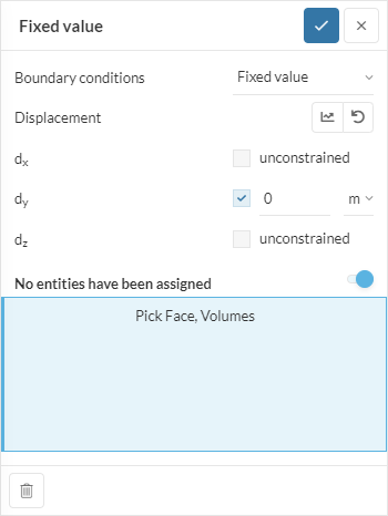
Bear in mind that you should constraint in all directions in at least one of the faces, to block the rigid body motion.
1 Like
Hi, thanks for your help.
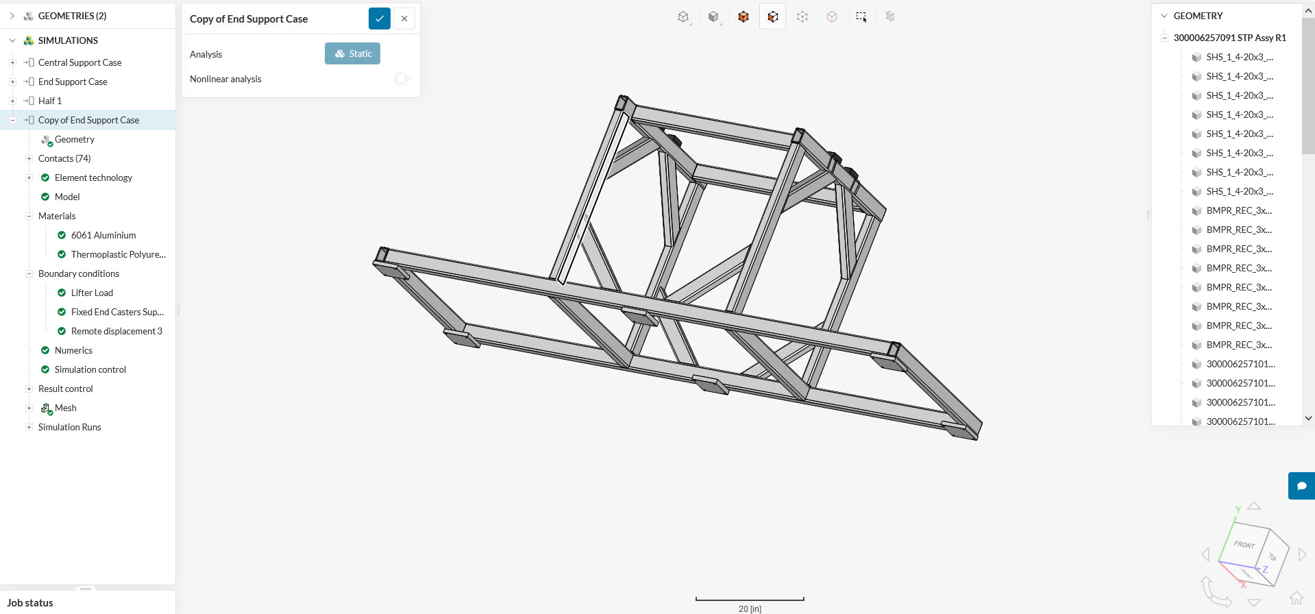
As this is a cart with wheels, it’s not really supposed to be “fixed” in any location. The six square pads on the bottom are where the casters (rollers) will be. I want to model it such that the middle pads are not touching the ground (worst-case) and it rests on the four corners.
As a start, I tried to fix the pads on one end and allow the other end to roll, but even then the results are not realistic and it doesn’t behave like a roller. The two long end-to-end beams should be in simple bending (tension on bottom, compression on top), yet “fixing” an end limits the deflection so that tension and compression switch near the fixed end.
I tried cutting it in half, fixed the cut plane, then applied a load to the pads (rather than just allowing them to be reactions) and got better results. I did a little better by modeling the entire thing, placing opposing loads on the small black pads on top (where the actual load goes) and the square pads on the bottom, then fixing the pads in the middle to make the nodes converge. However, it’s still not quite right and this still does not make a rolling reaction on either end.
I hope this helps you understand what I’m trying to do.
Hi,
Thanks for your suggestion, but this frame will bend and develop stress in the long members like simple beams. I have tried this and been unsuccessful in having a proper roller reaction and deflection OR it does not solve at all (that’s what usually happens with certain unconstrained combinations). You may look at my work. There are lots of attempts.
Hey there, I understand!
The next thing you can try to free the rotations is to apply a ‘Remote Displacement’ boundary condition. Here is the documentation for it:
And a related validation case as an example application:
The basic setup would be:
- Constrain all displacements to zero
- Free the rotations that coincide with your roller rotation axis
1 Like