In external aerodynamic studies, it’s common that the user wants to analyze their geometries (e.g. airfoils) at various angles of attack.
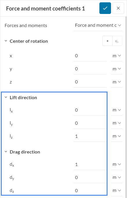
For such projects, the lift and drag coefficients are parameters that users are commonly interested in. These values can be obtained with a forces and moments coefficients result control. In cases where the angle of attack is not zero degrees, additional caution needs to be exercised with the drag and lift directions:
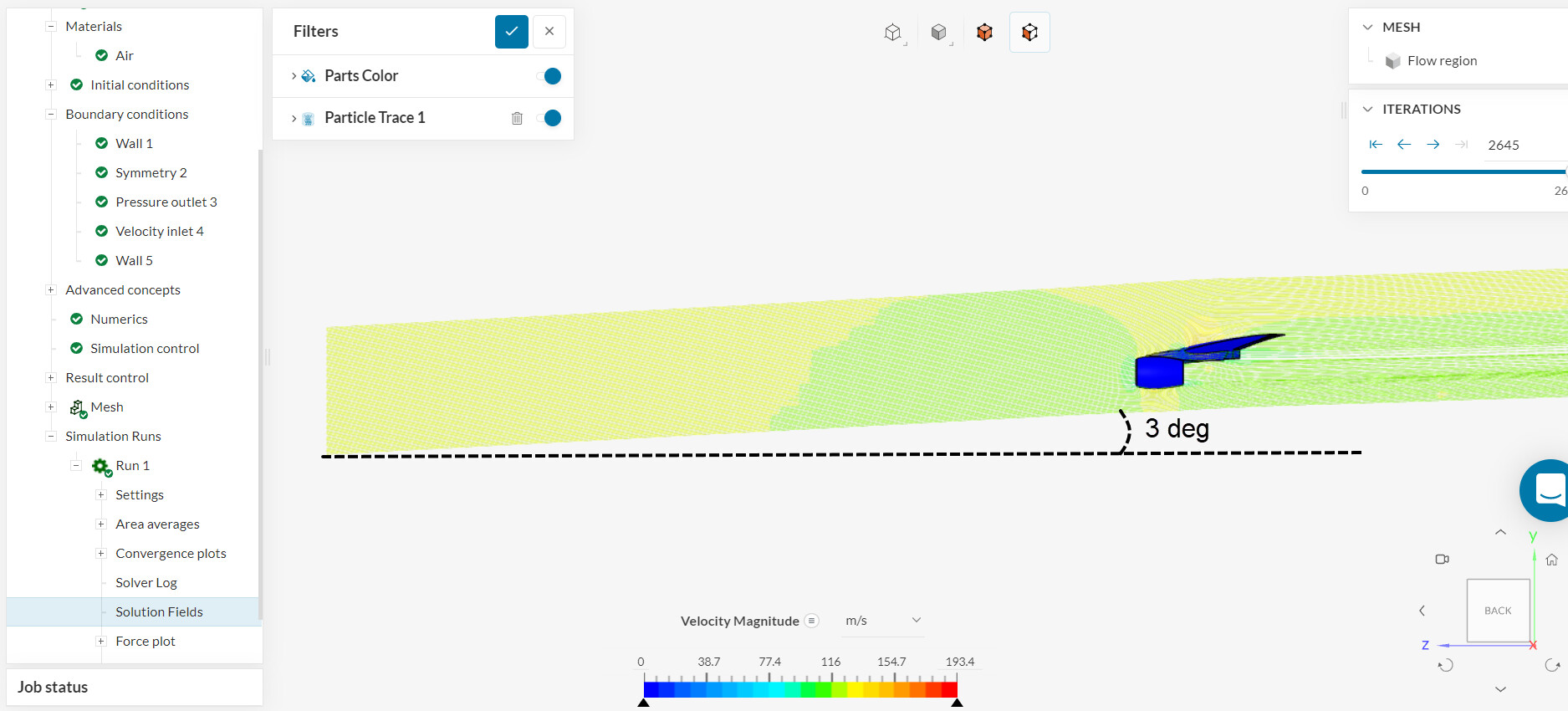
Let’s take the Compressible Flow Simulation Around a Wing tutorial as an example. In this project, the simulation consists of an external aerodynamic study with an angle of attack of 3 degrees:
By definition, the drag force is in the same direction of the flow, and the lift force is perpendicular to drag. Therefore, these are the directions that we are looking for:
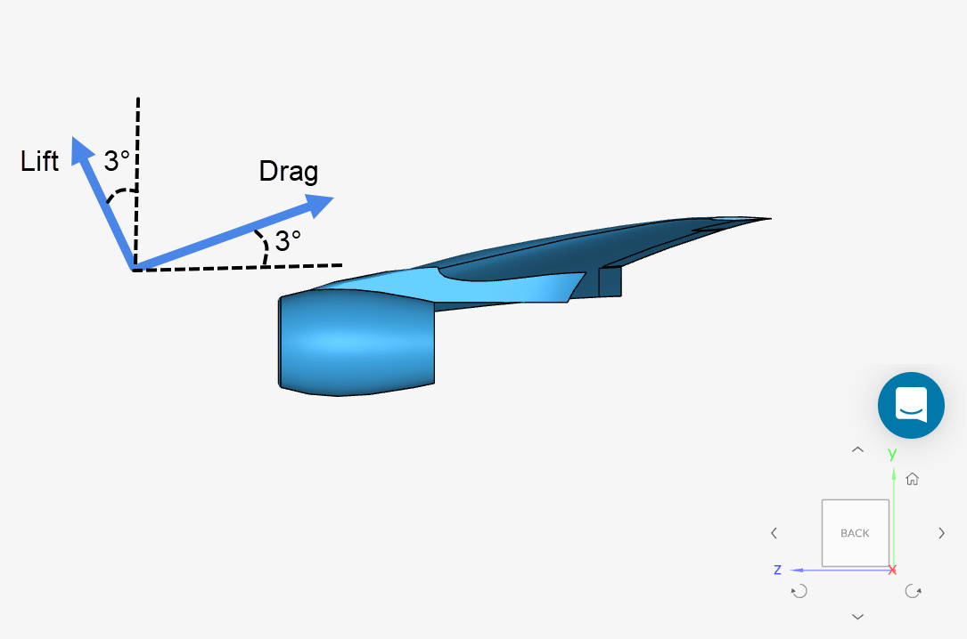
As such, given the orientation of the wing, here is how the set up would look like for this configuration (see the orientation cube in the image above):
-
Lift direction:
→ X = 0
→ Y = + cos(3°) = + 0.99862953475
→ Z = + sin(3°) = + 0.05233595624 -
Drag direction:
→ X = 0
→ Y = + sin(3°) = + 0.05233595624
→ Z = - cos(3°) = - 0.99862953475

By following this practice, you can obtain the lift and drag coefficients for any angle of attach of interest.