TurbineStudy001 | SimScale Workbench
I set up this tutorial example with the geometry of turbine blades based from golden spirals and the most basic cylindrical nose cone with an outer hull. How to set up the turbine blades and nose cone portion as a rotating zone where the blades and nose cone rotate together at some RPM if possible? How to check a flow rate and start to find out how many foot pounds of thrust a system like this creates just through a simple cylindrical hull to begin with?
Later on after posting I realized that in order for things to work at all there needs to be a geometry for the inner volume and the exterior volume. I also realized that compressible simulations are not a part of my current tier with SimSclae and I can only set up an incompressible simulation. To remedy those issues I created this project:
JetTurbineStudy002 | SimScale Workbench
So far my understanding is that in order to turn on forces and moments for the turbine assembly that the mesh maybe needs to first be generated however when I use the “Generate” button of the mesh dialog I have these issues still left to work through:
Simulation setup has errors
The physics can not be taken into account as the simulation setup is not valid. Complete your simulation setup before generating the mesh in order to optimize the mesh for your application.

Validation errors:

Please ensure that all CAD entities are assigned a material or advanced concept. Missing material or advanced concepts were detected for the following entities: 7A

The tool body 76 is assigned only to advanced concepts, but it interferes with multiple bodies assigned to materials. Tool bodies must intersect with only one material body. Please check your CAD model.

Multiple bodies with material assignments were detected. Because this is a single region simulation, only a single body may be assigned a material. Please review your material assignments and leave only the flow volume with a material.
So far I had assigned the turbine assembly a material of “Air” and also boundary conditions of wall for the whole turbine geometry. What I need to do is get things to the point where the RPM that is assigned (rads/sec in this case…) can be simulated…
I have no idea what these unresolved mesh errors have to do with or how to solve them. Could it be addressed what is wrong?
Through some mesh modifications I was finally able to get the meshing process to start up without the errors:
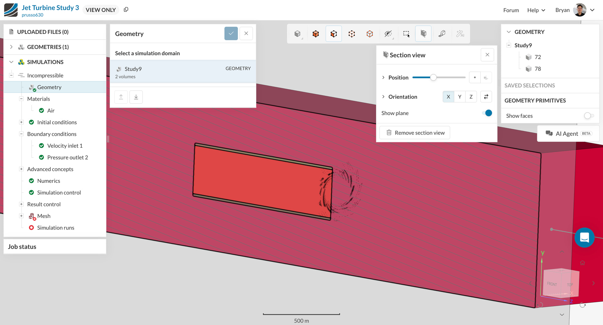
Jet Turbine Study 3 | SimScale Workbench
The above 3’rd study, is what I have set up so far…I am not really sure what the resultant simulation will actually do yet… What I am interested in finding out is the thrust forces out of the hull’s outlet face…
Hi @prusso630
The reason the mesh fails to generate is because your geometry contains multiple solids assigned as flow region (see attachment 1), although you fixed it in the third attempt, I don’t think that it is physically right, since now the flow will not go through the turbine only around the hull, now the setup is just like a flow around a rectangular cylinder.
Additionally you also did not include any rotating zone in the setup, meaning that even if the flow goes through it would be just like a flow going through a static/not moving turbine.
I would highly recommend you to take a look at these tutorials;
Creating Flow Region
Drone Simulation
Flow around a wing
Although the third tutorial is a compressible flow simulation, it is also good for you to see how the flow region should look like around the hull/nacelle.
Thanks!
Bryan