I’m a hobbyist who knows just enough to get in trouble.
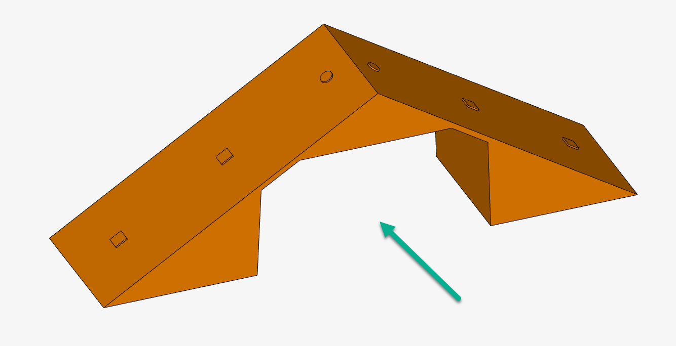
I wanted to see how the placement of an intake vent in our oddly shaped attic space would affect the venting of hot air. I created a model of air space of the unfinished section of our attic. For simplicity, I thought I would create a slice of the attic, rather than include the whole thing.
I’m using Conjugate Heat Transfer v2, which might not even be the right simulation type. I added the Solar Calculator, hopefully to add heat to the roof. The general air temperature is 80 degrees F, inside and out. I know the sun hits the roof and warms it up and then the heat is transferred to the attic air, but I’m not sure how to set that up.
It would be a lot to ask to have someone set up the model correctly for me (although if you find it easy and can do it in a minute or two, that would be great), so does anyone have an existing model which I could use as a guide? Or perhaps there’s a simple tutorial? Most of the ones I’ve found are for more complex entities such as office buildings.
I’m really just looking for the comparative difference in moving an intake vent higher or lower. Attic intake vents are normally installed at the lowest point feasible in the unfinished attic space. Our contractor installed intake vents over halfway up the attic. I suspect this affects the performance of the passive ventilation, and I’m trying to see if demonstrate the difference.
Thanks for any help. I realize that, unassisted, the odds of my setting this up correctly is about nil. If there are better (free) tools than SimScale for answering my question, that would be great, too.
Also, perhaps you might want to perform a convective heat transfer simulation in this case.
For simplicity, I would change the solar load condition for a simple wall heat flux with the absorbed power as heat source. Otherwise, you need to assign derived heat flux boundary condition to properly capture the sunlight heating. Check the following page for details:
I think that you are not far away from having a representative model and results.
First, yes, the volume represents the unfinished attic air space. The void in the center is the finished attic. To get a useful model, I think I have to
Account for solar heating on a composition roof.
Account for the heat transferred by the roof to the interior.
Account for the insulation of the finished attic walls and the attic floor.
Assign a constant heat value on the non-attic side of those walls and floors.
Since I just want to study the differences between a low and high intake vent, I wonder if I could just create walls with constant heat values. I tried this by defining walls with specific temperature values as the initial conditions, but perhaps I’m looking for walls that function as heat sources throughout the simulation. It sounds as though there is some way to set that up.
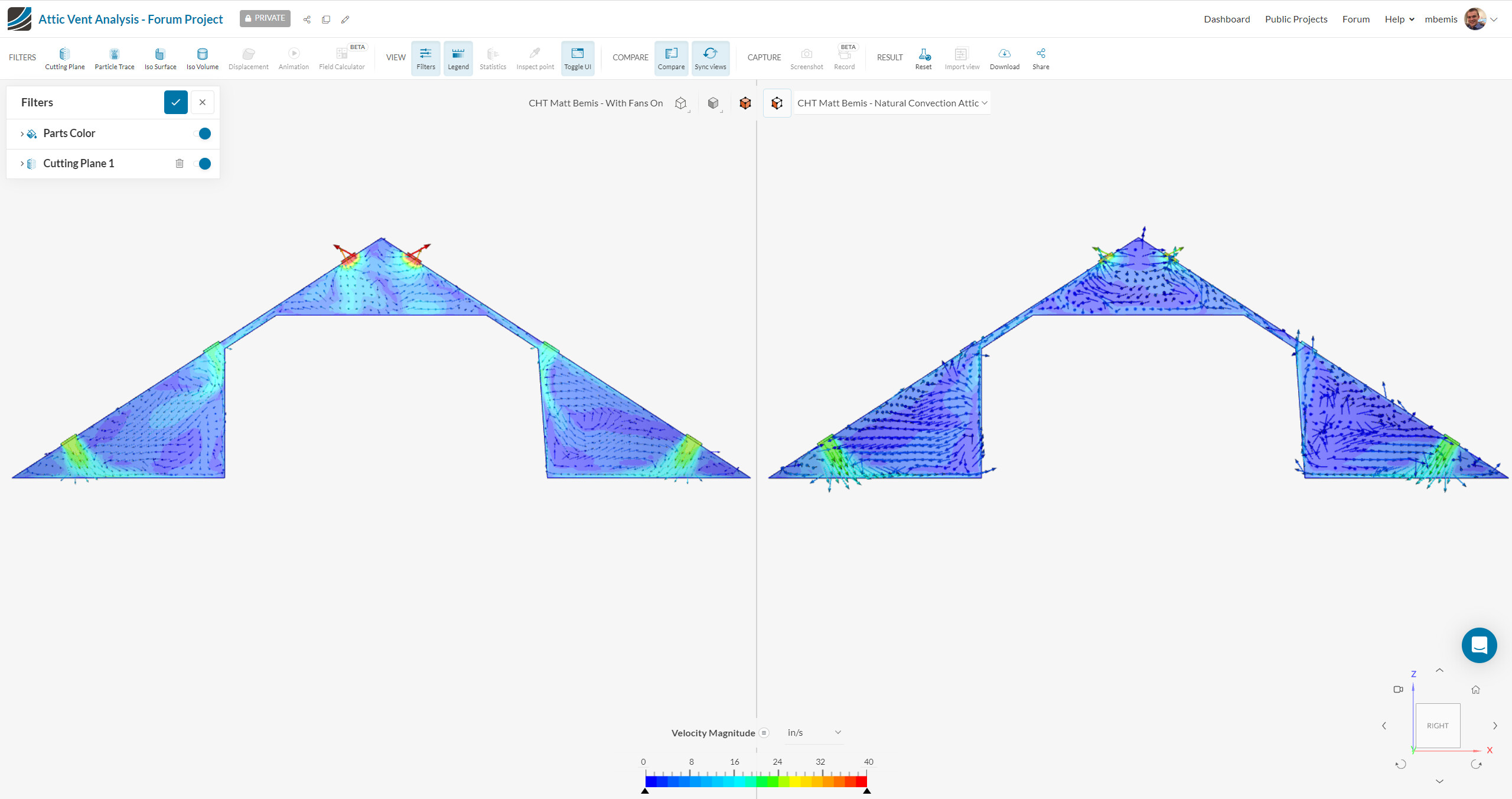
For what it’s worth, I managed to set up and run a pair of simulations that appear to have given reasonable results. I took @ggiraldof’s advice and ran a connective heat transfer simulation. I then designated “walls” for the roof heated to 160° F and walls for the interior heated to 80° F.
I am glad that you were able to setup your case and have acceptable results.
Of course you can start adding more complex conditions as you need, which should make the results more precise.
For example, you can use a ‘derived heat flux’ on the roof, and for the ‘wall thermal’ condition, select one of the models to capture the heat isolation of the roof, plus the actual heating load of the sun.
For the internal walls and floor you can also do something similar, by using a heat transfer coefficient plus ambient temperature of the adjacent rooms.
Please check this page for info on these more advanced models:
About your question on the walls being heat sources, you can set this up with the heating power, or with fixed temperatures as you state. On the later case, the wall can act as a power source or power sink, depending on the temperature of the fluid adjacent to the wall compared to the wall temperature.
Thanks! Setting the values properly might be a bit beyond me, particularly the roof. But yes, one can always get a better simulation. I could, for example, study the entire attic and not just a slice. The rafters are also important, as they block sideways air flow through the passage the connects the two attic sections.
@freixas - thanks for reaching out on the forum. I made a copy of your project, made a changes, and ran a few simulations. Please check out my version of your project here.
A few comments:
*You do not need 1 boundary condition per 1 face. You can apply a natural convection inlet/outlet BC to all 6 attic vents with a single BC.
*I recommend using a convection coefficient to approximate the adjacent flow volumes/spaces and heat to/from these faces. A standard natural convection analysis usually has a convection coefficient around 5-10 W/m2-K. I defined a convection coefficient of 5 W/m2-K with a reference temperature of 72 F on the faces on the inner section of the CAD. I believe this is a cavity in the attic that is probably an upstairs bedroom or office or something, so I chose 72 F as that’s pretty standard for human comfort.
*I used a convection coefficient on top of the roof to approximate heat into the roof from outside (convection). A 125 deg F ambient temperature is probably way too high; it probably makes sense to set that to outside ambient temperature and then use the same temperature value for the natural convection inlet/outlet BC.
*You can account for insulation, walls, etc, by using a “Layer thermal wall” to consider the effects of layers of materials. In my project, I state that the roof has 6 inches of glass wool insulation (thermal conductivity ~0.04 W/(m-K).
Thanks so much for not only taking a look, but running some simulations.
The reason I created a separate boundary condition for each vent was because I was unsure whether some later analysis would require that I keep them separate. Is there a performance penalty?
The point here was to compare two alternate configurations; therefore, no one simulation should use all six vents. The top exhaust vents are in both configurations. The mid-level and bottom-most vents are in one or the other.
The attic sits at the top level of the house. The modeled volume surrounds a finished attic area, so your assumption is correct.: the inner walls (but also the attic floor) are heated/cooled living spaces. 72 degrees would be nice, but my 80 degree setting (or worse) is more realistic for us in the summer.
I set the roof “wall” to 160 degrees because I understand roofs can get that hot and hotter. By choosing an extreme temperature, I thought that the differences in the two venting configurations (which is all I am interested in) might become more apparent.
A reasonable ambient temperature for my purposes might be 90-110 degrees F. The way I modeled the system, the ambient temperature was mostly irrelevant.
The floor and the inner walls are insulated. I’d have to check the R factor. The underside of the roof is not insulated.
If I were trying to model the system on a typical summer day, I would probably want to activate the Solar module, but I would have to know more about the characteristics of the roof. I know the shingles get hotter than the ambient temperature; I don’t have a clue how to model their absorption of sunlight. Then there’s a felt layer, then a 1/2" plywood layer, so I would need have to select all the right models and numbers to use given all this. If accuracy were my goal, it would be easy to fail to achieve it.
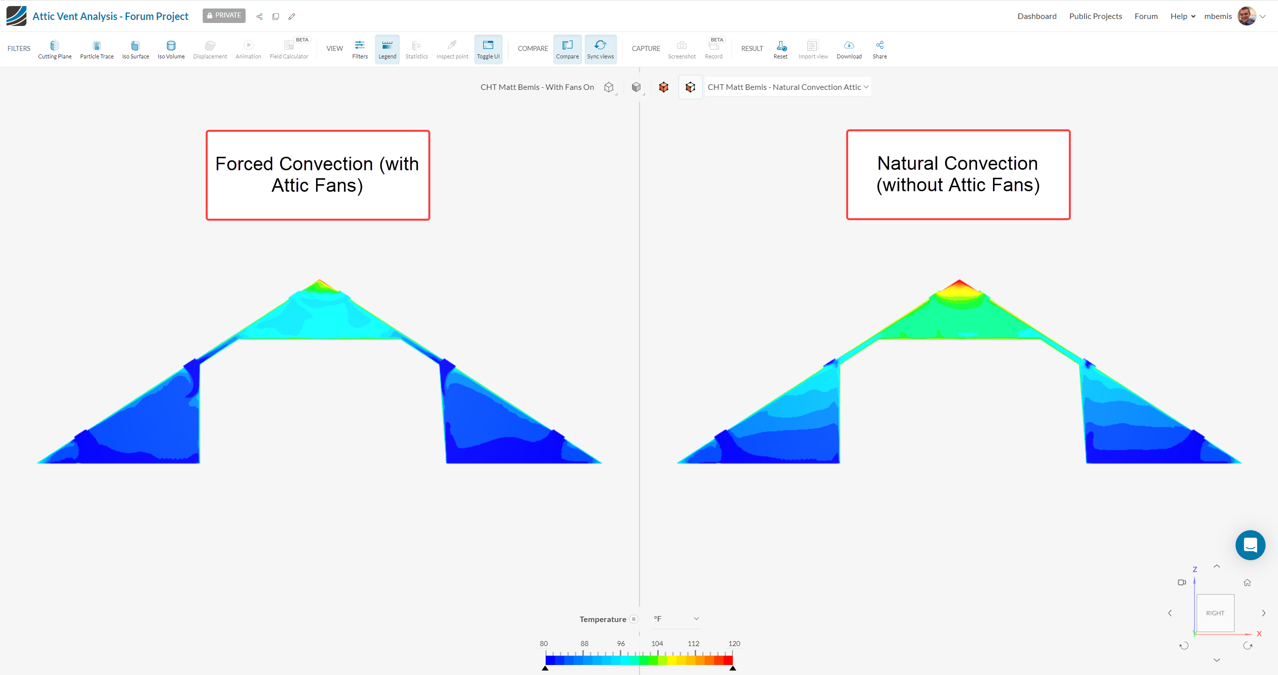
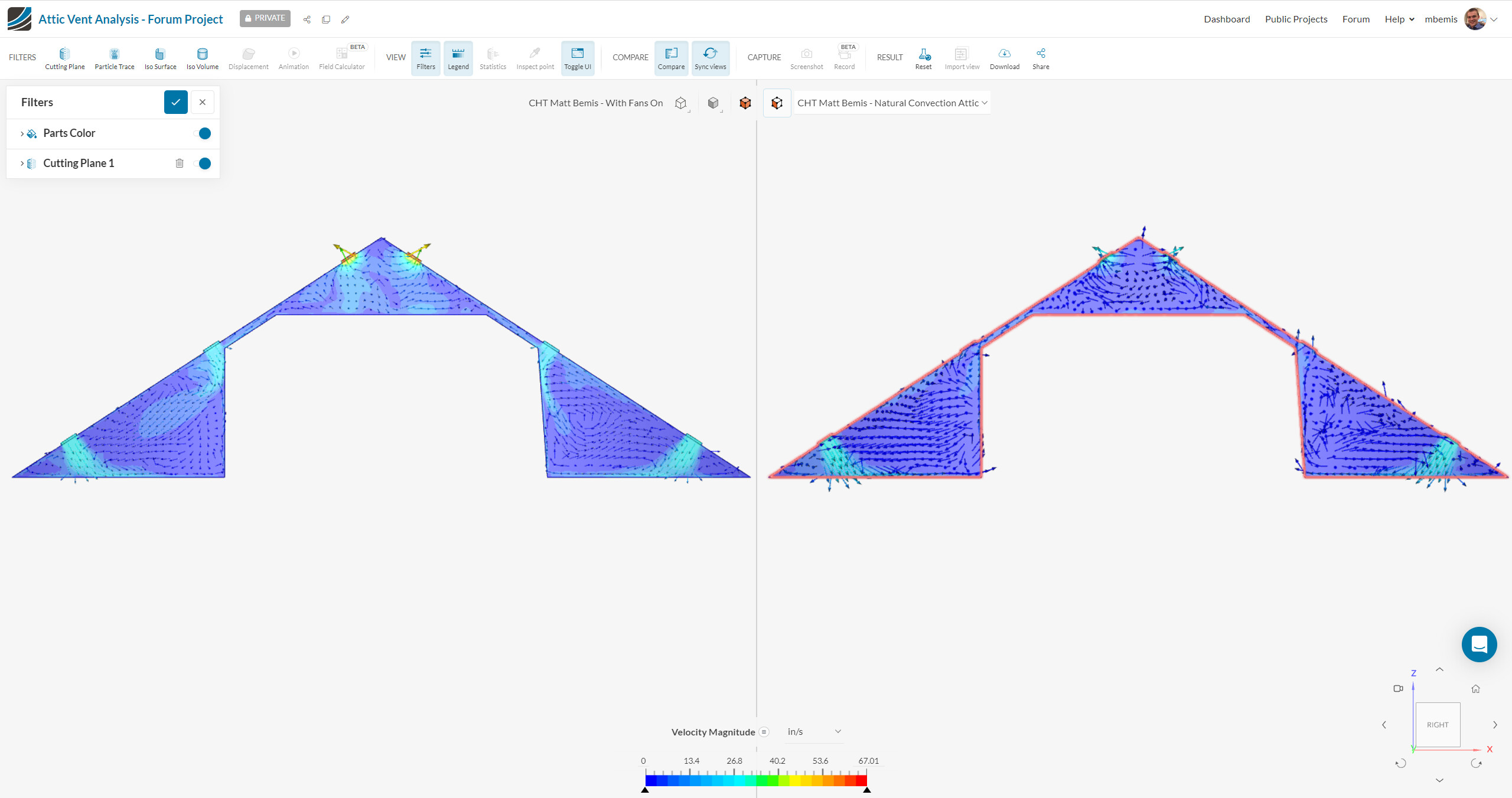
Luckily, I don’t need an accurate model, I just need to know how the two venting configurations differ. The answer I got matches what I think most people would expect: using the lower vents results in cooler temperatures with faster air flows and more exhaust.
@freixas thanks for all the additional information! Interesting application and I’m glad you were able to successfully compare the two different designs. To answer one of your questions: The reason I created a separate boundary condition for each vent was because I was unsure whether some later analysis would require that I keep them separate. Is there a performance penalty? There is no performance penalty. The way you set up your project with the separate BCs is completely fine, and definitely makes sense if you were planning to make BC changes to the individual faces. Just trying to save you a few clicks
Since you and @ggiraldof are both on the SimScale Team, I thought I’d mention how I plan to use this simulation.
For attic ventilation, the universal consensus is to place intake vents as low as possible, but I have been unable to find any studies that prove that this is the case. This is important since my roof contractor, for some reason I cannot fathom, installed our “intake” vents over halfway up the roof. Repositioning the vents is going to be an expensive fix for them so I expect to meet some resistance. This simulation may help overcome that resistance, so the simulation is not just an intellectual exercise.