CAD Preparation
Intro
Starting at the foundation of a problem free simulation is having the correct CAD geometry. This fact cannot be overstated enough as this has been proven time and time again over the course of testing. Therefore, there are two main concepts that must be understood.
- Having a correct CAD Geometry has a HUGE IMPACT on the resulting mesh quality. If not prepared correctly, the mesh could possibly fail.
- A good mesh will result in an accurate simulation. In addition, a bad mesh WILL cause divergence or possibly simulation failure.
.
Therefore, spend time on a good CAD geometry. It should be a reiterative process of meshing, fixing geometry, mesh again, fix geometry again, and so on … Attempting a simulation should be left you know that the mesh quality is good enough to support one. DONT RUSH IT , you will just burn through core hours. A half car mesh should be around 50-80 core hours, full car mesh around 100. Also, a cleaner geometry will reduce the computational effort needed, even with an increased number of cells. Quality over Quantity!
Basic rules for good CAD geometry
1. No intersecting geometry
Fairly self-explanatory, any features that are physically intersecting each other will cause errors. These can come from misaligning parts in an assembly file or forgetting to combine solids. In any case the geometry should be thoroughly inspected.
2. No Small Gaps or surfaces
Most small areas will only cause problems in meshing. Unless they are critical to the performance of the car, they should be simplified or in some cases deleted. Below is an example of a 1st try for simplifying the suspension geometry. While meshing was successful, it was still too complicated and unnecessary.
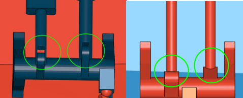
Complicated…,…,…,…,…,…,…,…,…,…,…,..,.. Simplified
.
3. Unexpected Faults
Not all problems with CAD geometry are easy to find. In this example, there was a crease or overlapping surface problem with the loft feature used to create the driver dummies arm. This problem was only identifiable when the model was uploaded to Simscale.
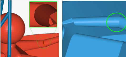
Problem area …,…,…,…,…,…,…,…,…,…,…,…,..,..,..,.., Fixed with new Loft Feature
.
4. No Highly acute angles
The last basic tip comes from an extension of the Simscale FSAE tutorial where a “contact patch” is required where the wheel meets the floor of the wind tunnel. This is because during snapping, this very small angle causes the algorithm to not know where to put the cells, and bridging occurs. Shown below is the point where the dummy driver head meets the headrest. When filled with its own “contact patch” the mesh conforms much better.
Dummy Driver Head to Headrest …,..,…,…, Head to Headrest with Contact Patch
Cell size appropriate for corresponding geometry feature
This section covers a more advanced topic, describing the connection between meshing and geometry. This is where looping through meshing and geometry repair begins. It is difficult to give an overall best methods solution as this can be highly dependent on the geometry. However, as a general guideline, these examples cover the main issues and will help speed up the process of obtaining a good mesh.
Example 1: Trailing edges of wing profiles
One of the best examples is the trailing edge of the wing profiles. They are usually very thin (1-2mm) and require a very fine mesh to be accurately represented. This means that the cell size (surface refinement) would have to be very high, increasing total cell count. Shown below is a thin trailing edge face at 1mm thick. The lowest cell size around the wing is 3.2mm, shown in blue, which means that during the snapping phase, these cells must somehow attempt to accurately represent the geometry and this does not always happen.

.
There are two common results when the cell size is too large for the geometry.
1 . Boundary layers get deleted (Not good)

OR
.
2 .Bad Geometry Conformation (also not good)
Since the trailing edge is an extremely important area, it is crucial to monitor this area for a correct mesh. There are two main options for this area.
-
(Better Solution - my Opinion) Delete the trailing edge face and join the trailing edge to make a sharp point. The trailing edge is only as thick as the laminated wing surface anyways.
-
(Worse Solution - my Opinion) Thicken the trailing edge face so that a finer cell size can be applied. I don’t like this option because this would mean a face thickness of 3-5mm which is unrealistic and could affect slot gap geometry.
Example 2: Other Thin Surfaces
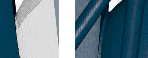
For other surfaces, such as endplate edges, that are also normally thin (2-5mm) it is also important to have accurate geometry conformation. While these areas are less influential on performance, the quality of the mesh will degrade if they are not addressed. In this case, it is much easier to simply increase the wall thickness to meet a cell size that snaps correctly. This is an area where geometry accuracy (in this case applying an incorrect endplate thickness) should be used so that the mesh as a whole can succeed. Shown below is an example of bad vs good mesh conformation.

Bad - cells to coarse …,…,…,…,…,…,…,…,…,…,…,…,…,…,…,…, Good - cells match geometry size
There are other snapping and mesh conformity issues not related to geometry that can cause low quality. This can occur when the geometry lies in an awkward angle in the domain and is due to the hexahedral mesh application. However, this problem will be described in the next section.
Advanced CAD Preparation
At this point you should have been able to get a few successful meshes. While there is a possibility of a simulation achieving convergence, the quality of the mesh can be analyzed further so that time and resources can be saved. By improving the mesh even further, the following will occur:
- Meshing failures will become less likely
- Meshing Time will be reduced
- Core hours used to mesh will be reduced
- Simulation result accuracy will increase
.
The best way to analyze the mesh is with the Simscale Mesh Quality feature. After a successful mesh, the solutions field window is opened and viewing the cells in different ways is possible. The three main areas are:
- Cell Non-Orthogonality
- Cell Volume Ratio
- Cell Volume
Cell Non-Orthogonality
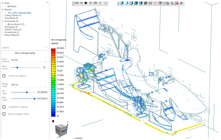
For the first example, I will focus on Non-Orthogonality. This quality measure is very important to satisfy as very high degrees of Non-orthogonality will cause mesh failures. Shown below is a screenshot of mesh non-orthogonality set from 60 degrees in dark blue until 90 degrees in red. Generally, any cell that has a non-orthogonality angle over 65 deg will start to give inaccurate results in the simulation. A more detailed explanation on this will be given later.
Slot Gap Cell Distortion
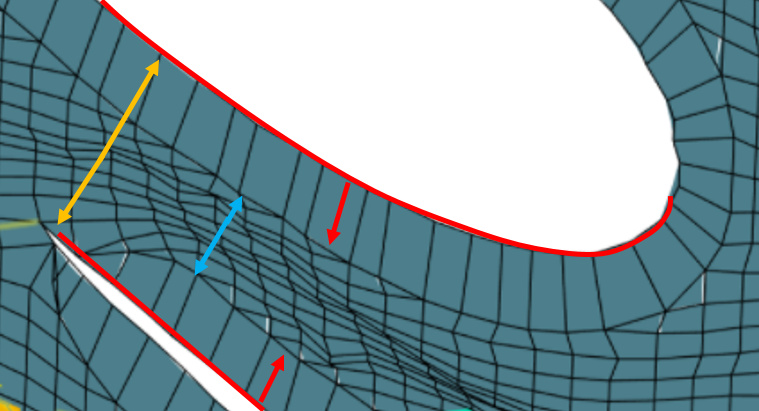
As you can see below, the areas between the main wings and elements are blue. While this is not optimal, the mesh in this area must accommodate boundary layer cells on both wing geometries and have space for the original HEX cells. This is the main reason for the focus and validation of the single cell boundary layer method.
In OpenFOAM, HEX cells are applied to the geometry first and boundary layers are extruded outwards. This is a rather unfortunate method as any HEX cells in the way will be pushed, distorted, and twisted, leading to illegal cell conditions. Shown below is the single cell boundary layer method with a 3.4mm thickness (Red). The optimal slot gap between wing profiles was determined to be 13mm (Orange). This may be even less for your application. This means that two opposing boundary layers already equal 6.8mm leaving only 6.2mm (Blue) of space left for HEX cells to fill from their original application distance of 13mm. This results in the cell squish shown in the picture.
Using the Mesh Quality feature in Simscale, these areas of high Non-Orthogonality or skewness can be found and improved. In this case, there is not an easy fix due to the slot gap requirements. However, slightly reducing the boundary layer thickness in combination with cell size level adjustments can help to improve the Non-orthogonality in this area.
Non-Orthogonal cells on other surfaces
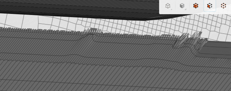
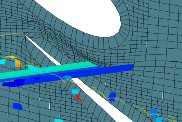
Illegal cells can plague almost every area of the mesh and they increase significantly when there is a limit to the total cells available. For a full car simulation, it is crucial to apply the coarsest cells possible to unimportant areas in order to have save cell fineness for wing surfaces. However, problem areas cannot be ignored because it effects the total mesh quality. Shown below is a geometry that was thick enough to support the applied cells however had an odd angle in relation to the HEX cells within the domain. This caused problems during snapping iterations and cell quality was lost. Using the Mesh Quality feature, areas such as this can be found and fixed be altering the CAD geometry. A solution in this case could be adding a radius or chamfer to the area or changing the angle slightly.
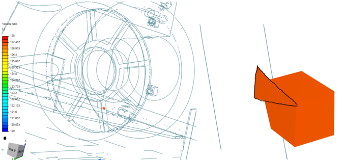
Volume Ratio
The next method to observe illegal cells is the volume ratio. This is defined as follows:
The minimum face volume ratio metric is calculated as the ratio of the minimum of the owner and neighbor volume divided by the maximum of the two.
To find cells with high volume ratio it is best to first check the meshing log for the MAX volume ratio value. In this example this was 127. Generally, values under 100 are ok for meshing and do not need to be investigated.
Mesh quality metrics:
volumeRatio
min: 1
max: 127.30383812624176
average: 1.9344380679072968
standard deviation 2.238841743549893
median: 1.01776657513619
0-th percentile: 1
20-th percentile: 1.0007451708371224
40-th percentile: 1.0085491033167777
60-th percentile: 1.041526107217848
80-th percentile: 1.5668483744319996
100-th percentile: 127.30383812624176
Using the mesh quality feature, the volume ratio can now be set from 120 MIN to 128 MAX. This will show the problem area, which happened to be in the wheel. Zooming in we see that the two cells in question do have quite a difference in size. Problems such as this can also be fixed by applying fillets or chamfers to the CAD geometry.
Illegal Cells Causing Divergence
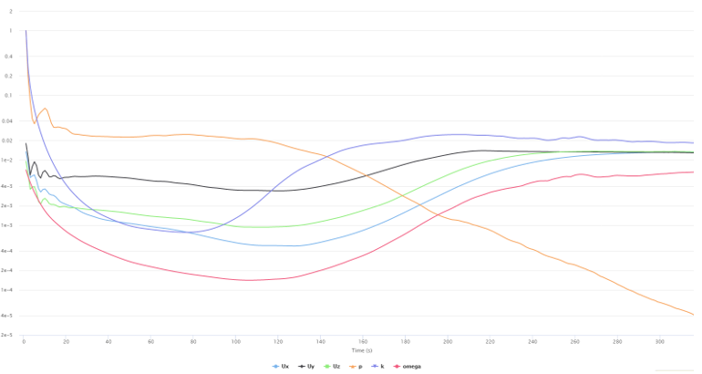
Another good example of inspecting illegal cells comes from a scenario I encountered when multiple simulations were diverging, and of every other common failure cause was exhausted. Shown below is the clearly diverging residuals graph that was terminated after 300 iterations. Seeking help from Ricardopg, he suggested that I look at the solutions field.
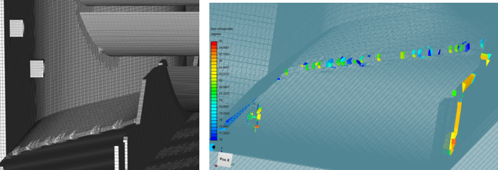
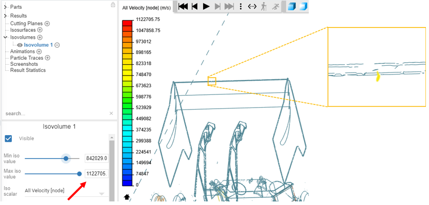
Because of the divergence in the domain, the force results are unrealistic. In my case there was an extremely high spike in velocity. This can be found by creating an Iso volume and setting the velocity to the max value. Shown below, my maximum velocity at the last iteration was 1122705 m/s( red arrow) which is a bit unrealistic. The iso volumes then show the affected area, which was on the gurney flap of the rear wing. This one cell (zoomed in yellow box) was the cause of the problem. Similar to previous methods the solution was changing CAD geometry to force the mesh to snap differently in this area.
SIMILAR DOCUMENTATION:
How to Tell When and Where the Simulation Starts Diverging?
Split faces method
The split face method was developed out of frustration due to successive mesh failures. In the case that CAD geometry changes are only moderately successful in reducing illegal cells, splitting the geometry into two different cell levels can have a huge impact. In addition, making drastic changes to CAD geometry in order to obtain good mesh conformation can lead to inaccuracies between the car that is simulated and what is actually built in the real world. Therefore, splitting geometry faces will help to do the following:
- Allow for cells to be applied to small features
- Increase mesh quality
- Allow for control over local cell fineness
In addition, this method has also been proven to also:
- Reduce Meshing Time
- Reduce Meshing Core Hours
- Reduce Simulation Time
- Reduce Simulation Core Hours
In order to obtain higher quality meshes, the face splitting method involves increasing mesh fineness only in critical areas. These critical areas could be:
- Leading and trailing edges of wing profiles
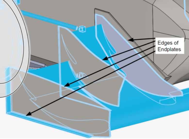
- Edges of Endplates
- Gurney Flaps
- Problem areas with bad mesh conformation
- Problem areas with illegal cells
.
With the addition of more cells, the expected result would be that it would extend meshing and simulation time and increase core hour consumption. On the contrary, the meshing and simulation time was reduced! The only downside to this method is that Total cell count will also increase. However, even with more cells added in the mesh, the higher quality of these cells reduces the computational strain during the castellation and snapping steps and can therefore solve the mesh or simulation faster.
Application of Split Faces Method
Normally, the only way to increase cell levels for edges or small geometries is to apply an unequal Min – Max cell level to a surface or use a feature refinement. The problem with these methods are that the application of finer cells is controlled through an angle designation. This means that they are applied to the entire selected geometry (with unequal min-max) or the entire model (feature refinement). This can result in higher level cell refinements in areas where they are not needed. This will be problematic when trying to stay under a total cell count limit.
The correlation between surface and distance region refinements
It is important to note that this method uses distance region refinements in order to achieve the smooth cell size reduction required for a good transition from large domain cells to the smaller surface refined cells. Using inner region refinements applied to cartesian boxes are good for wake resolution but can significantly increase total cell count when applied to large areas or when a high level refinement is used.
Distance region refinements do not conform to the change in cell level when using an unequal Min-Max Surface refinement. For example; a level 6 distance region refinement will override a level 5 – 6 surface refinement Min value and apply only level 6 over the selected surface. In contrast, when the distance region refinement is lower than the Max Surface refinement, like when its set to level 5, then it will override the Max surface refinement designation and apply level 5 cells over the surface. Therefore, it is necessary to use an equal Min-Max surface refinement that matches the distance region refinement cell level.
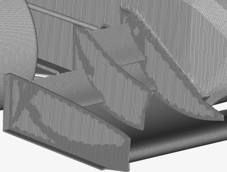
Using this refinement application method, we can now take full advantage of splitting faces. The best course of action is to physically split the necessary areas into separate solids within CAD. This allows for different cell levels to be applied along with the corresponding distance region refinement. Shown below is a comparison of the split faces method versus a normal refinement application.
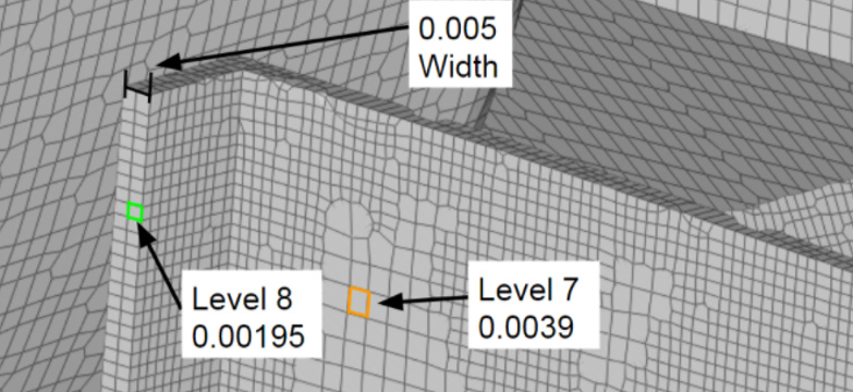
The following picture shows wing surface refinements at level 8 (0.0195m) and endplate refinements at level 7 (0.0039). It can be seen that the higher level 8 wing refinements will “infect” the surrounding mesh with the higher level, as shown by their profile outline on the outside of the endplate. It can also be observed that the edges of the endplates do not have good mesh to geometry conformation.
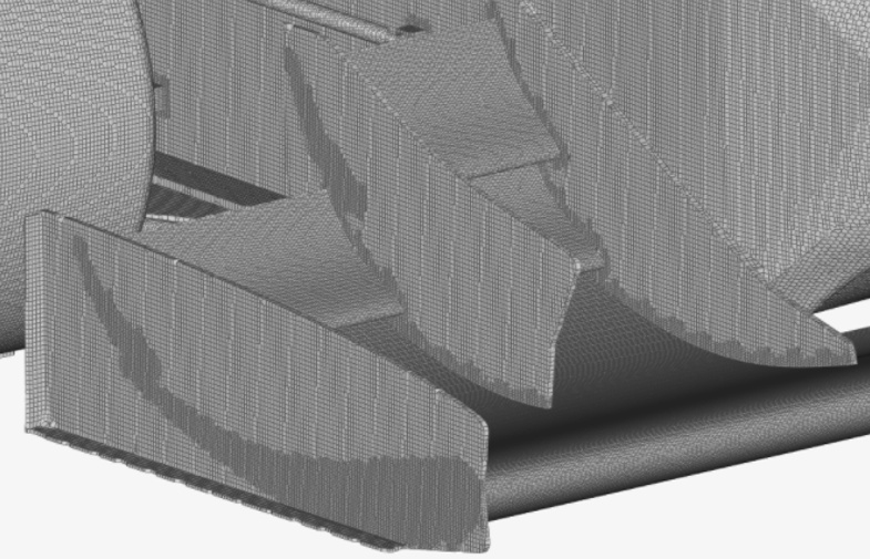
Zooming in on the endplate edges it can be seen that there is some cell skewing from the snapping process. This can occur when the cell size is too big or slightly smaller then the geometry it will be applied to. At the top of the outer endplate shown below, the cell size was appropriate for the geometry and minimum skewing occurred.
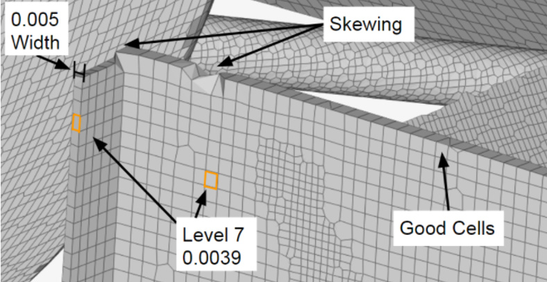
However. at the bottom of the endplate, the mesh had difficulty in applying the cells to the geometry and significant skewing occurred. Because the level 7 surface refinement was applied to the entire endplate, the only option to fix this cell skewness (other than thickening the geometry) would be to increase the level refinement to 8 and would significantly increase total cell count. In addition, mesh conformation over the main surface is sufficient at level 7.
In order to solve this problem, splitting the edges of the endplate geometry will allow for a level 8 designation in the area where it is needed – at the edges.
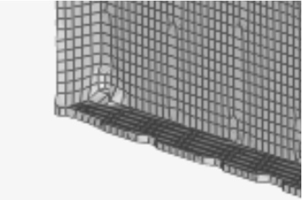
Shown below is the resulting mesh from endplate edges receiving level 8 refinement and main surfaces reviving level 7.
Zooming in again on the endplate, it can be seen that mesh conformation is much better. Generally, a minimum of 2 cells across a small geometrical face will help with mesh conformation. This is because the snapping process now has more points available to snap to and doesn’t have to cycle through iterations trying to find the correct geometrical location for mesh application. This is my theory on why meshing times are reduced with this method.
The split faces method can be applied to clean up features that cannot be altered by CAD changes. It should be used in areas where the model accuracy is significant to aerodynamic performance. In addition, it is useful in increasing cell fineness in localized areas when illegal cells are present.
For validated results, I have tested this method over 16 different mesh runs and recorded the meshing and simulation time and core hour usage.
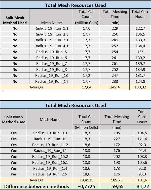
In the meshing process for a full car simulation:
- The average total mesh cell count INCREASED by 0.7725 million cells
- The average total mesh time DECREASED by about 1 hour
- The average total core hours used DECREASED by 31.72
.
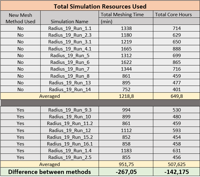
For a simulation run for 2000 iteration using 1 Non-orthogonal corrector loop:
- The average total simulation time DECREASED by about 267 minutes
- The average total core hours used DECREASED by 142.175
From these results, it can be postulated that total cell count is not the driving factor for increased meshing or simulation time. Rather, it is theorized that the quality of cells produced in the mesh lead to quicker solutions. It can also be seen how big of an effect the mesh quality has on simulation resources and turnaround time. Further supporting the requirement for mesh optimization before a simulation attempt.
Summary
Other than the advice in this article, the best guidance is given by the Simscale documentation about CAD preparation
Depending on the complexity and quality of your CAD model, some preparation and cleanup work might be required. Most of this cleanup work should be done before importing the model into SimScale. The following general guidelines might help get you to the first successful iteration of your simulation.
General Hints
Start simple and iterate
A proven strategy for the simulation setup is to create it for a very simple version of the problem in order to see whether or not the simulation approach is viable.
Think the complete workflow through
Having an idea about the mesh and the application of boundary conditions can help with CAD preparation.
Have a clear understanding of the problem
This helps to decide whether certain effects can be neglected or not.
.
.
.
.
Hope this can help anyone with CAD, Mesh, or Simulation Problems
Dan