Tutorial Updated 2018-01
Recording

Introduction
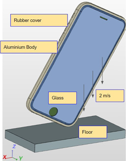
The FEA Master Class: Session 3 accentuates the physics governing a dynamic Finite Element Analysis (FEA) simulation. This exercise will help you set up an FEA study, simulating the drop of an iPhone 6 (with case) from a height of 20 cm. Moreover, you will be provided with the means to draw a comparison between the resultant impact of such a drop (a) with case (b) without case.
We begin the drop analysis by computing the speed of the iPhone on impact with the ground.
Let us assume that the height of the desk is equal to 20 cm (=0.2 m) from the ground.
According to the Law of Conservation of Energy,
Kinetic Energy (Initial State) + Potential Energy (Initial State) = Kinetic Energy (Final State) + Potential Energy (Final State)
Since the iPhone is stationary on the desk top at initial state,
Kinetic Energy (Initial State) = 0 …(1)
Since the ground is assumed to be the reference level,
Potential Energy (Final State) = 0 …(2)
From (1) and (2), we can conclude that:
Potential Energy (Initial State) = Kinetic Energy (Final State)
Therefore, we have:
Mass ∗ Acceleration due to gravity ∗ Desktop height = 1/2 ∗ Mass ∗ (Final velocity)²
10 m/s² ∗ 0.2 m = 0.5 ∗ (Final Velocity)²
Final Velocity = 2 m/s
The final velocity of the iPhone is its velocity on impact with the ground. On that account, you may note that:
Final velocity = Impact Velocity = 2 m/s
The constraints of the problem can be summed up and represented as follows:
Import Project
Please use the following link to begin your simulation:
Handout Project: Project Link
Mesh Generation
You will be directed to the Mesh Creator in the workflow. Select the Meshes in the Navigator and click New.
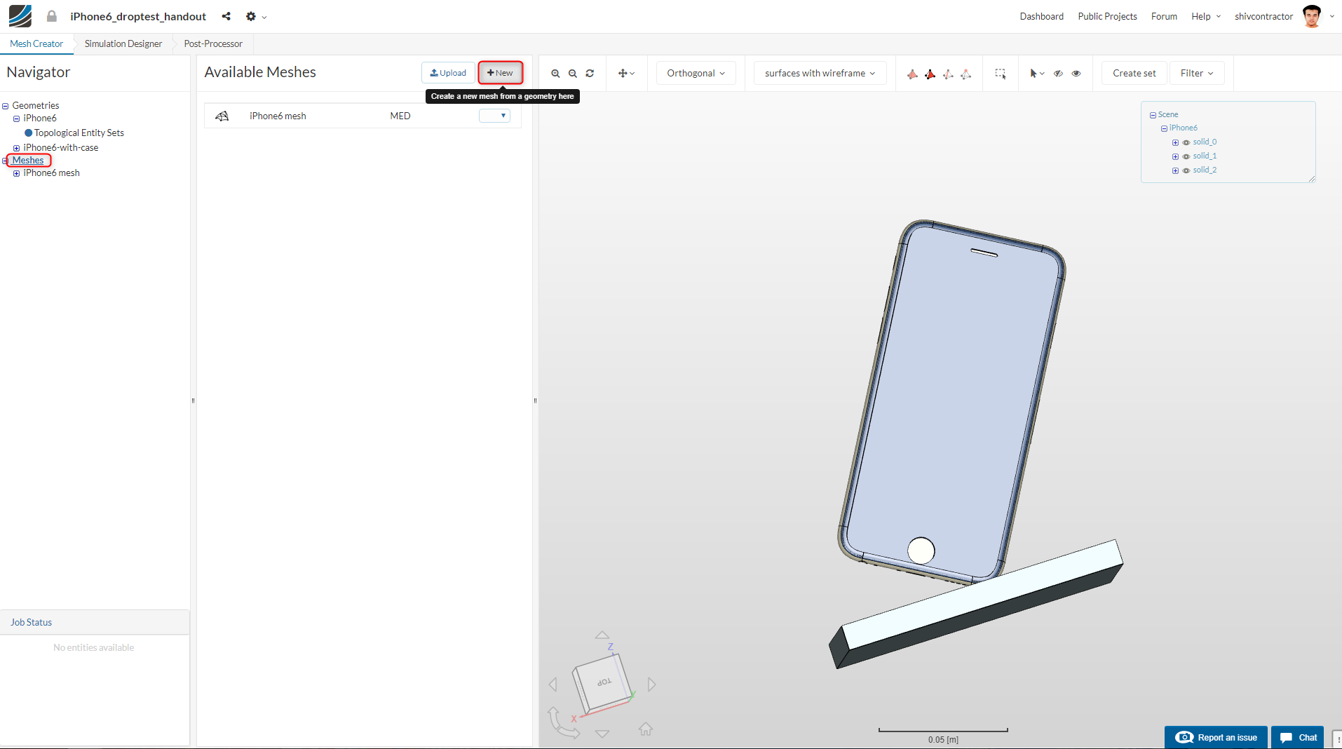
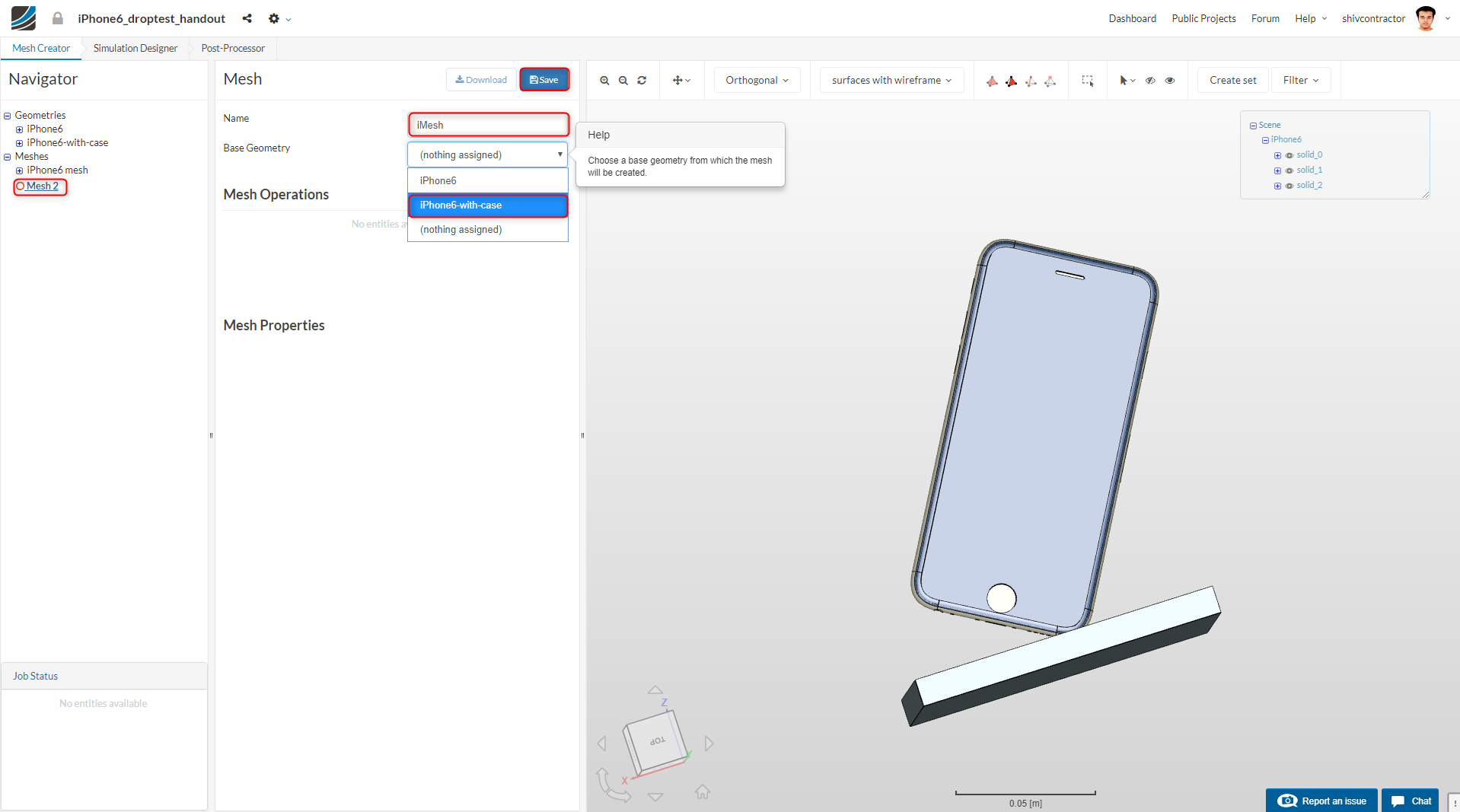
After assigning an appropriate Name to the mesh, select the Base Geometry as iPhone6-with-case.
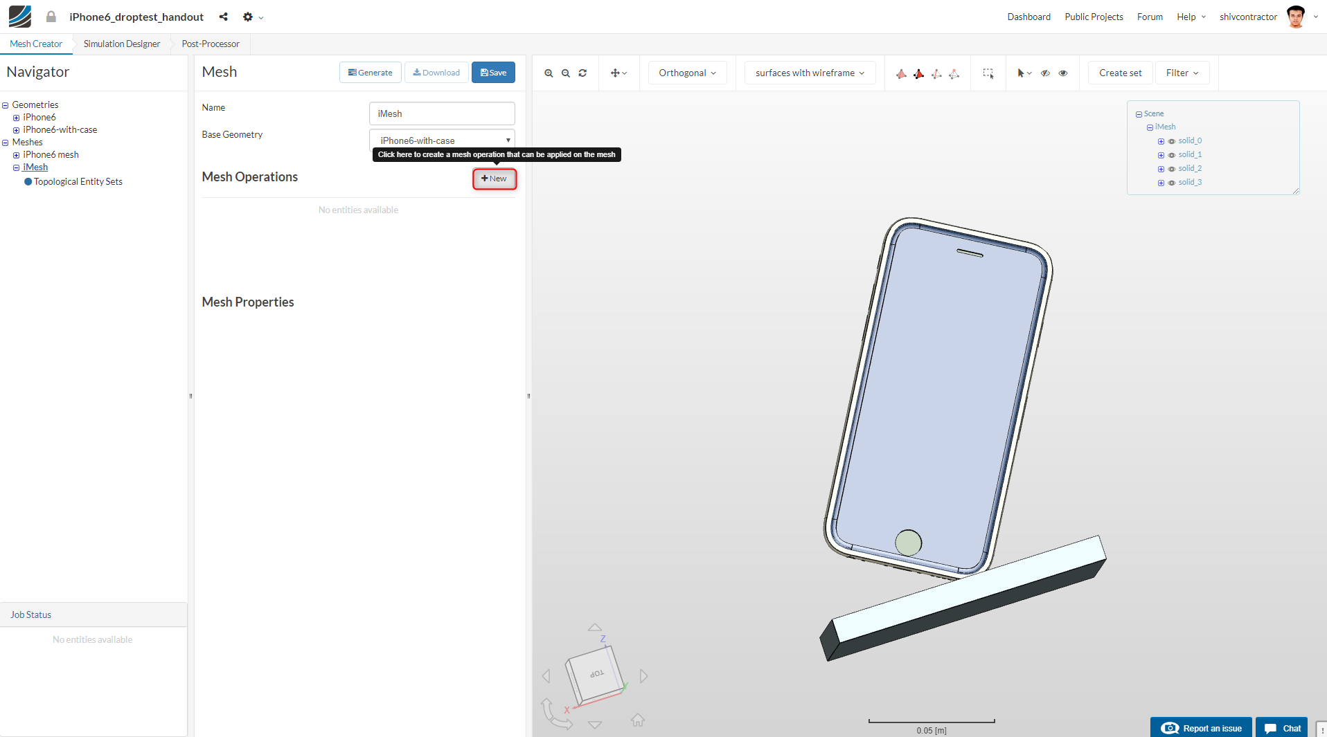
Subsequently, create a new Operation by clicking on New.
A Tet-dominant mesh operation is to be used for this FEA study. You may now set the global mesh sizing as:
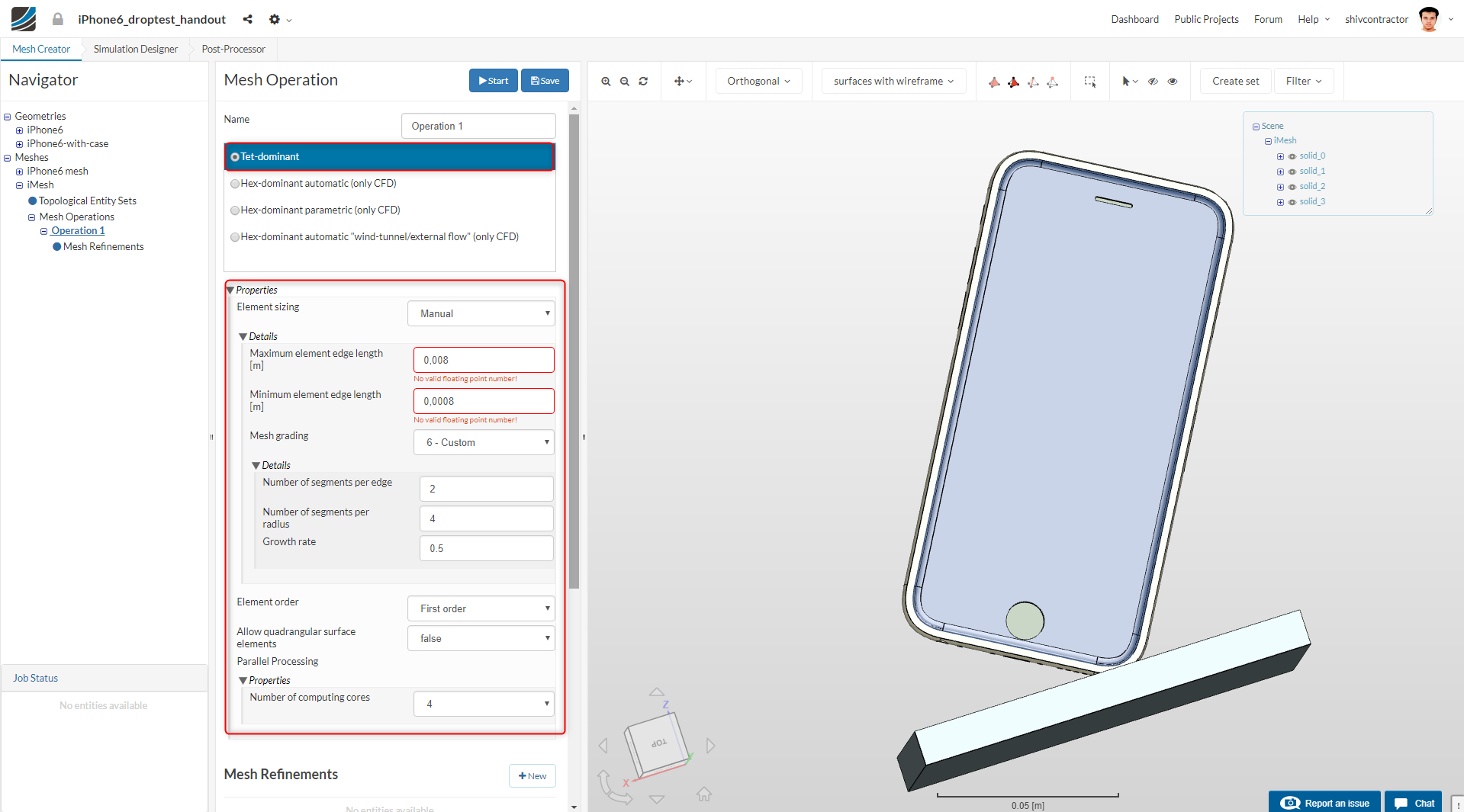
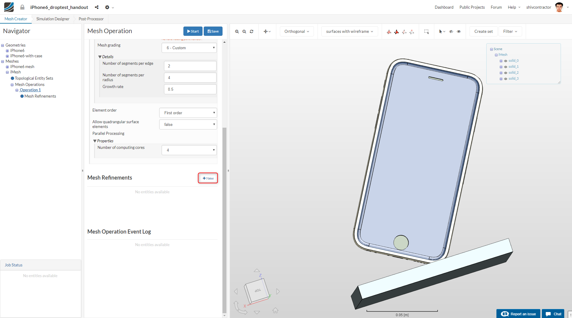
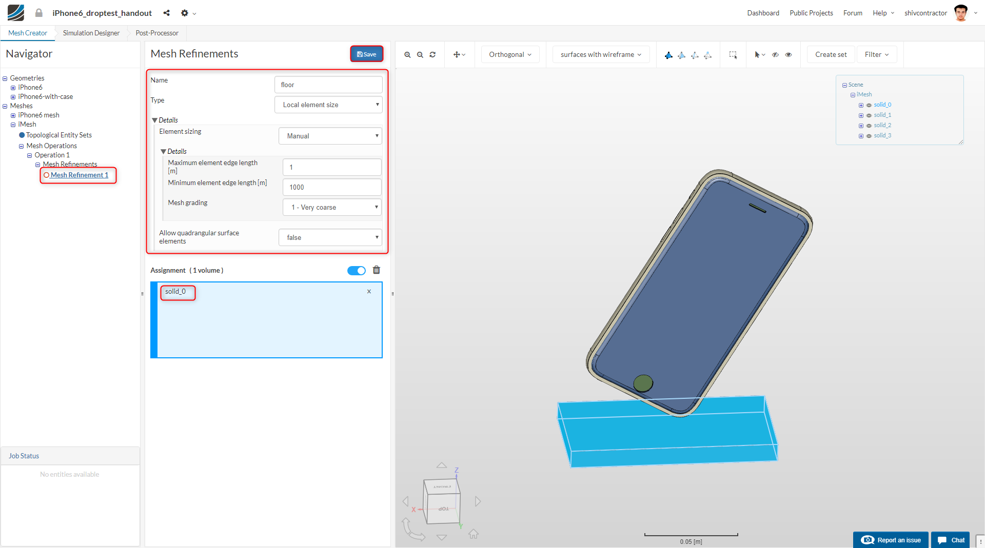
Set the Number of computing cores to 4 and proceed to make a mesh refinement by clicking on New.
Essentially, the floor is considered to be an immovable rigid support on which we do not intend to perform any calculations. Hence, we assign the coarsest possible mesh to it.
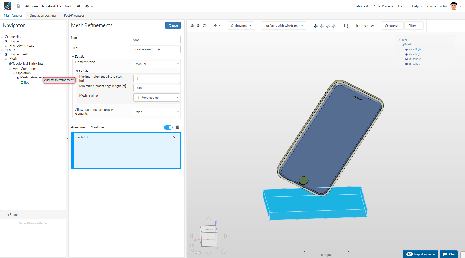
To make a new mesh refinement, right click on Mesh Refinements and select Add mesh refinement.
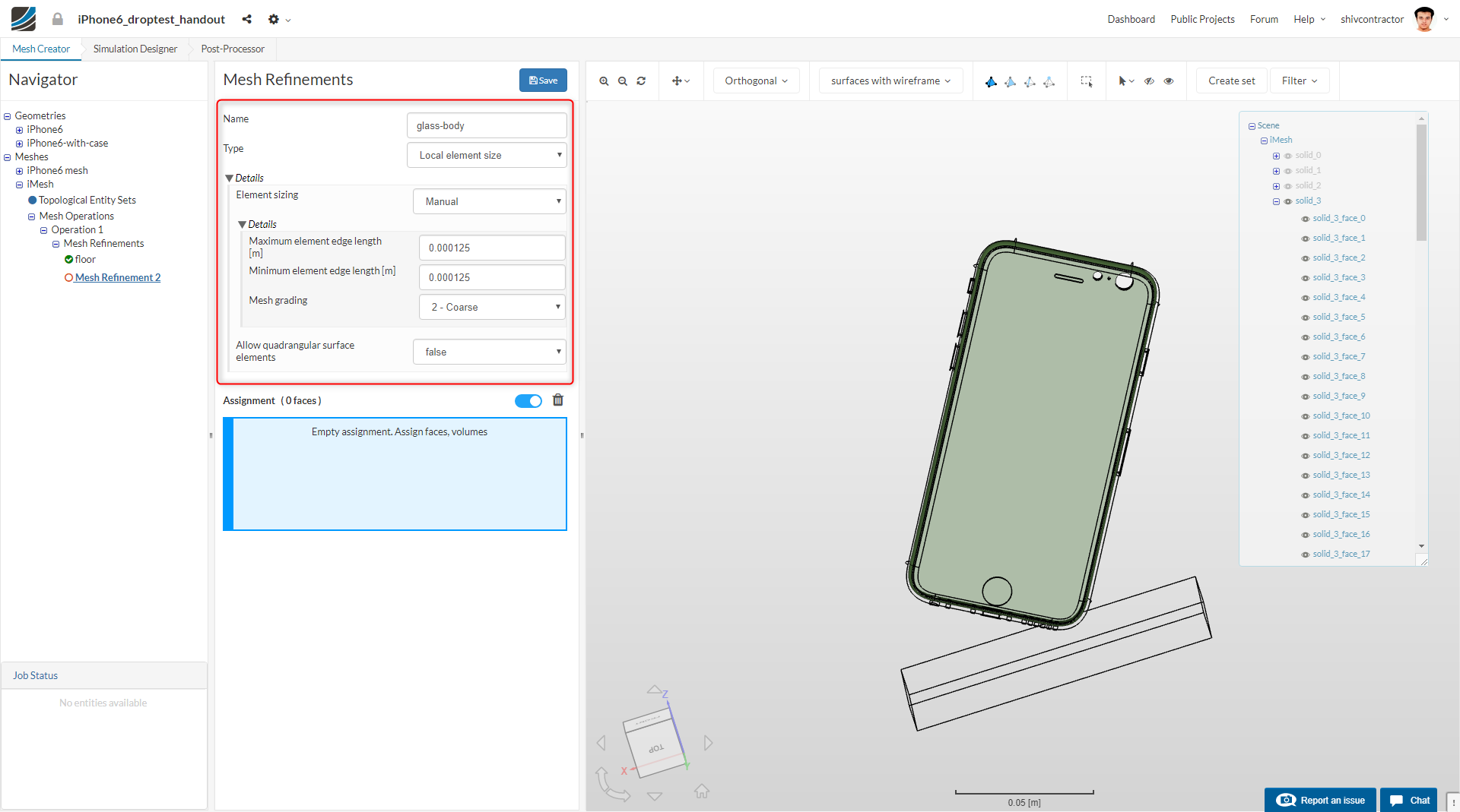
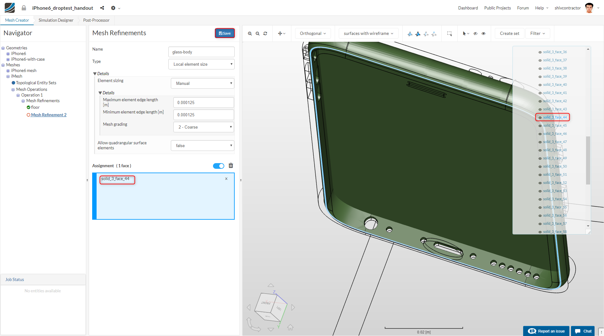
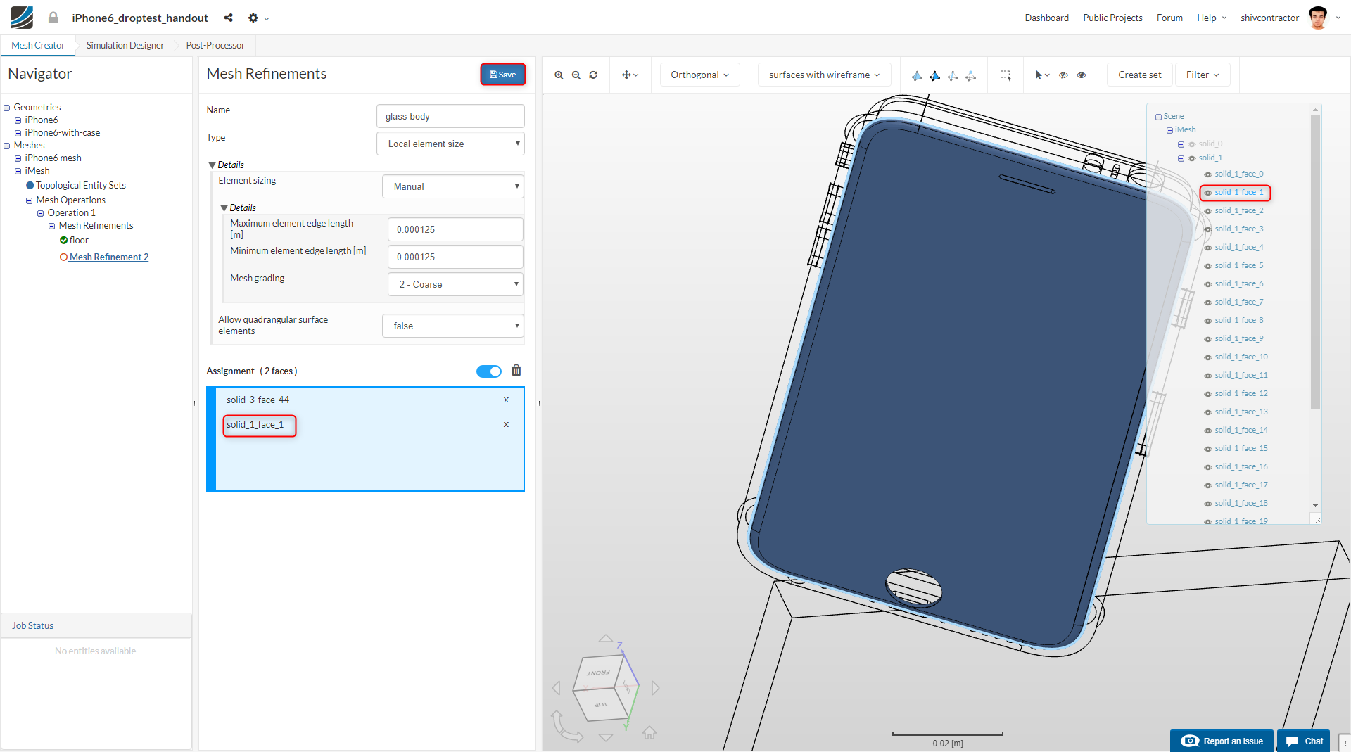
Now, we intend to refine the surface of the glass and that of the iPhone body, in contact with each other. Essentially, this would be the region of the iPhone body onto which the glass is glued. As depicted in the images below, select the surfaces from Solid 3 and Solid 1.
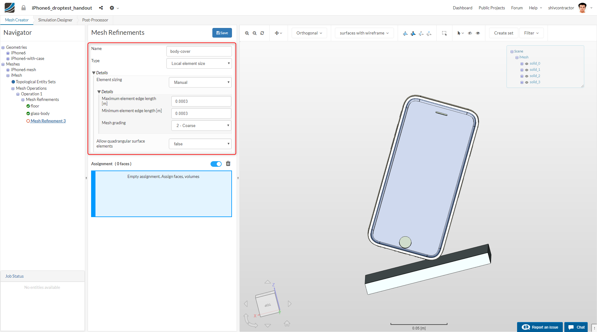
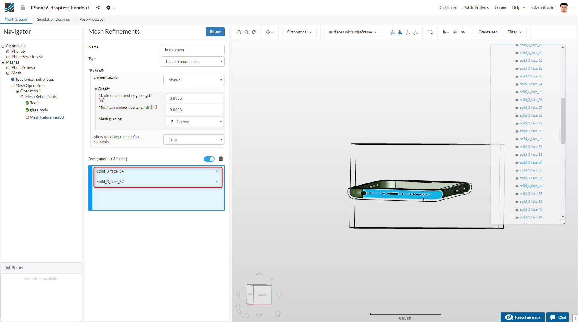
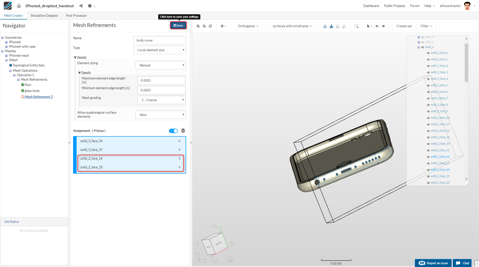
As shown earlier, create new mesh refinement and set it up for the interface of the body and the cover. The body-cover refinement is aimed at refining the mesh in the regions of the iPhone that undergo high stress on impact. As an analytical assumption, let us refine the lower surfaces of the cover and the body.
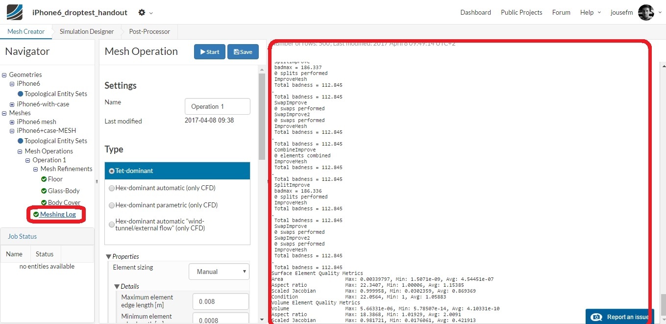
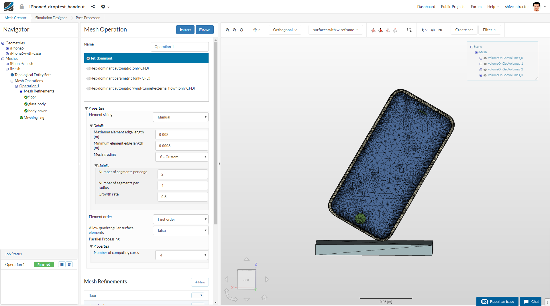
Once the global refinement and three local refinements have been set up, you may proceed to Start the mesh operation. Click on Operation 1 in the Navigator to open the Mesh Operation tab.
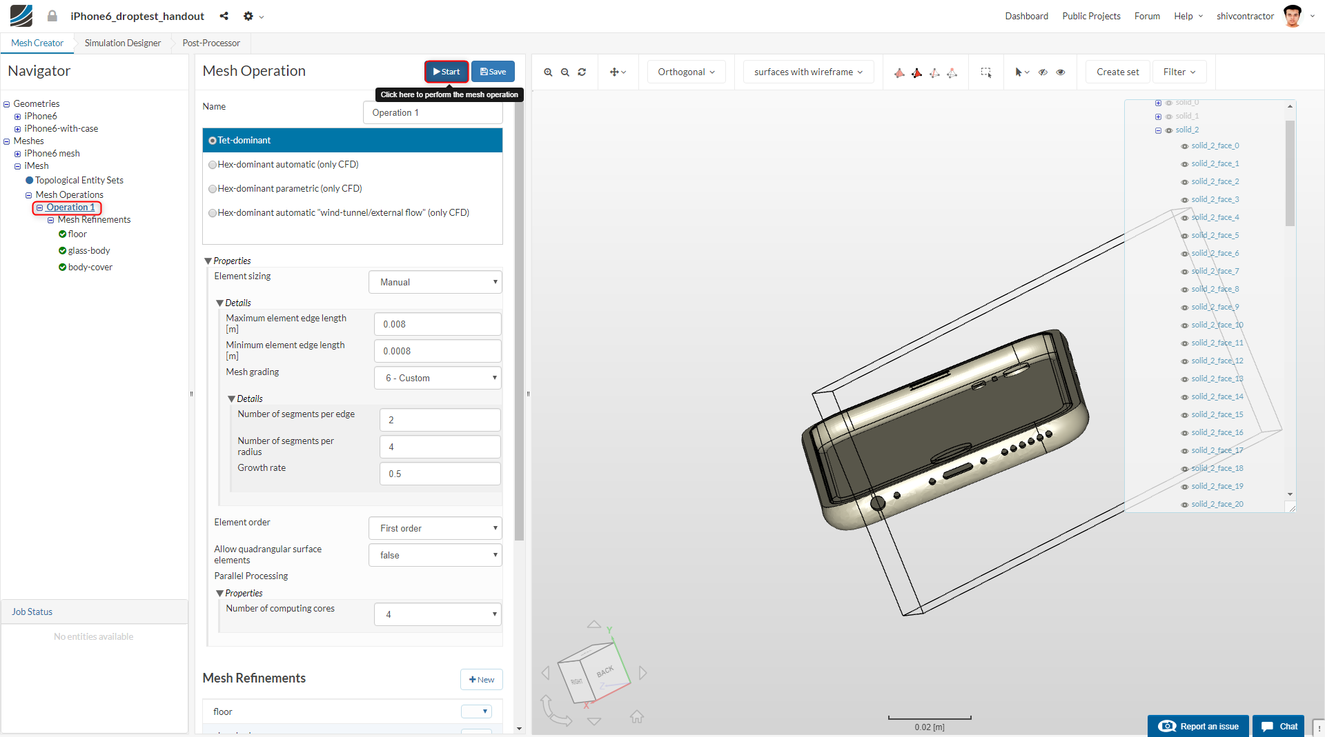
The mesh may now be visualized in the viewer.
Simulation Setup
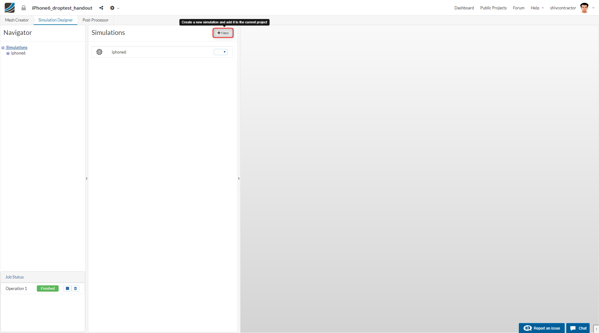
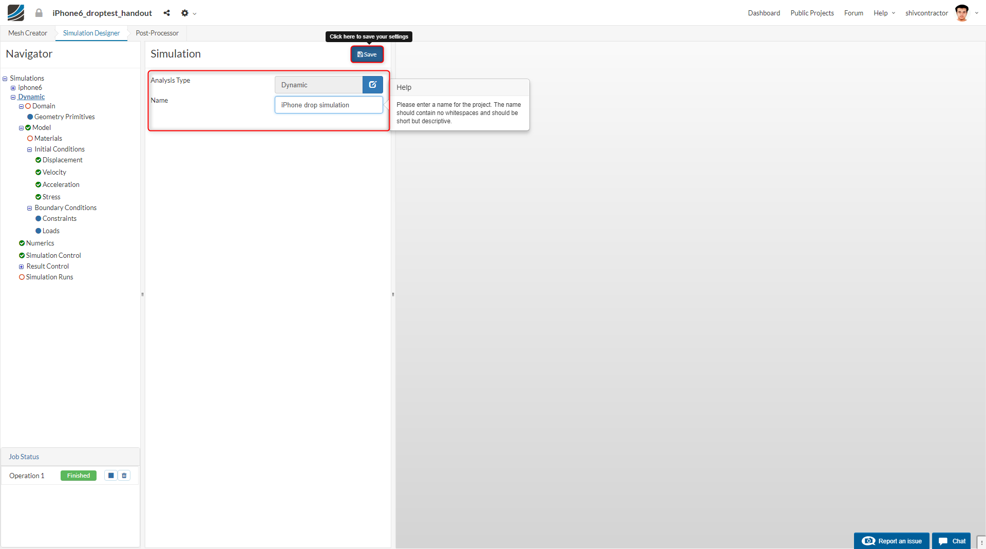
Navigate to the Simulation Designer in the workflow and click New to create a new Simulation setup.
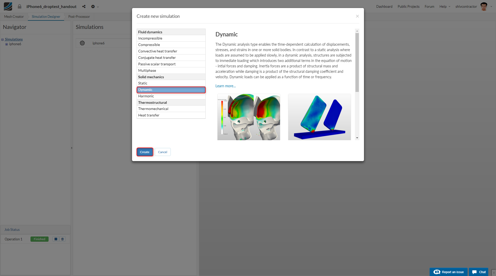
You will see an array of simulation types you can choose from. In our case, we choose the Dynamic analysis simulation under the category- Solid Mechanics.
Please assign an appropriate name to your simulation and Save to proceed.
Select Domain from the Navigator. You will be able to see the mesh that you have created. Select the desired mesh on which the simulation is to be performed.
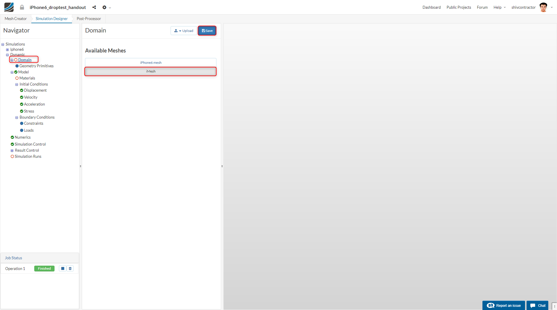
Kindly note: Please make sure to select the mesh you created and NOT iPhone6 Mesh.
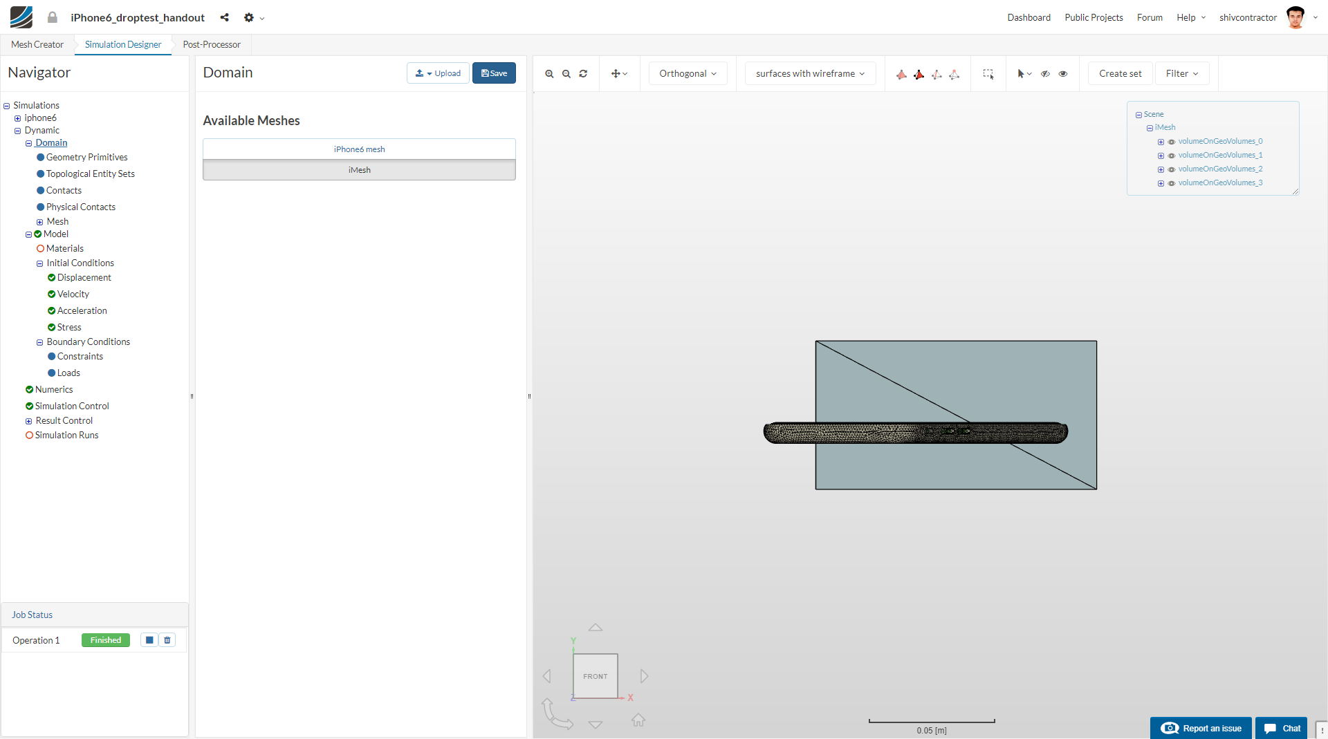
The mesh will be loaded and displayed on the viewer. Click Save to continue to the simulation set up.
Contact Definition
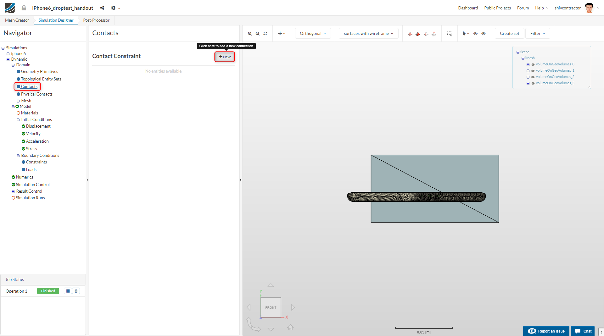
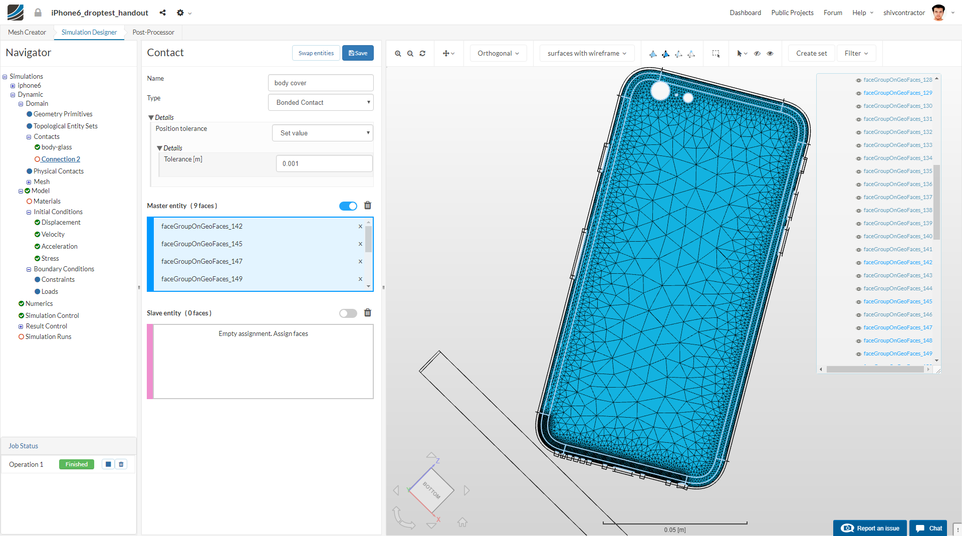
Let us move on to assigning the contacts. Select Contacts in the Navigator and create a New contact.
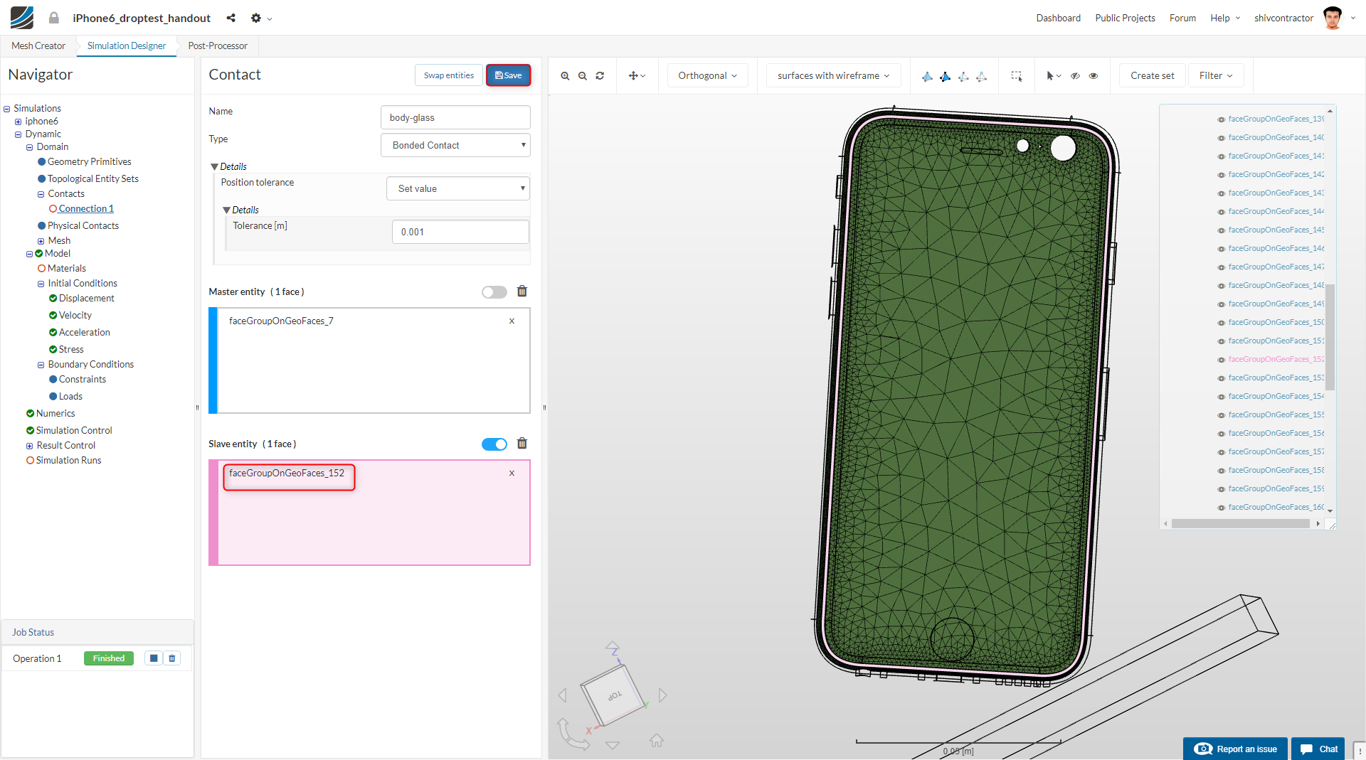
The first set of contacts, between the iPhone glass and the body is to be defined as a Bonded Contact. The thin surface of the glass in contact with the body is to be set as the Master Entity.
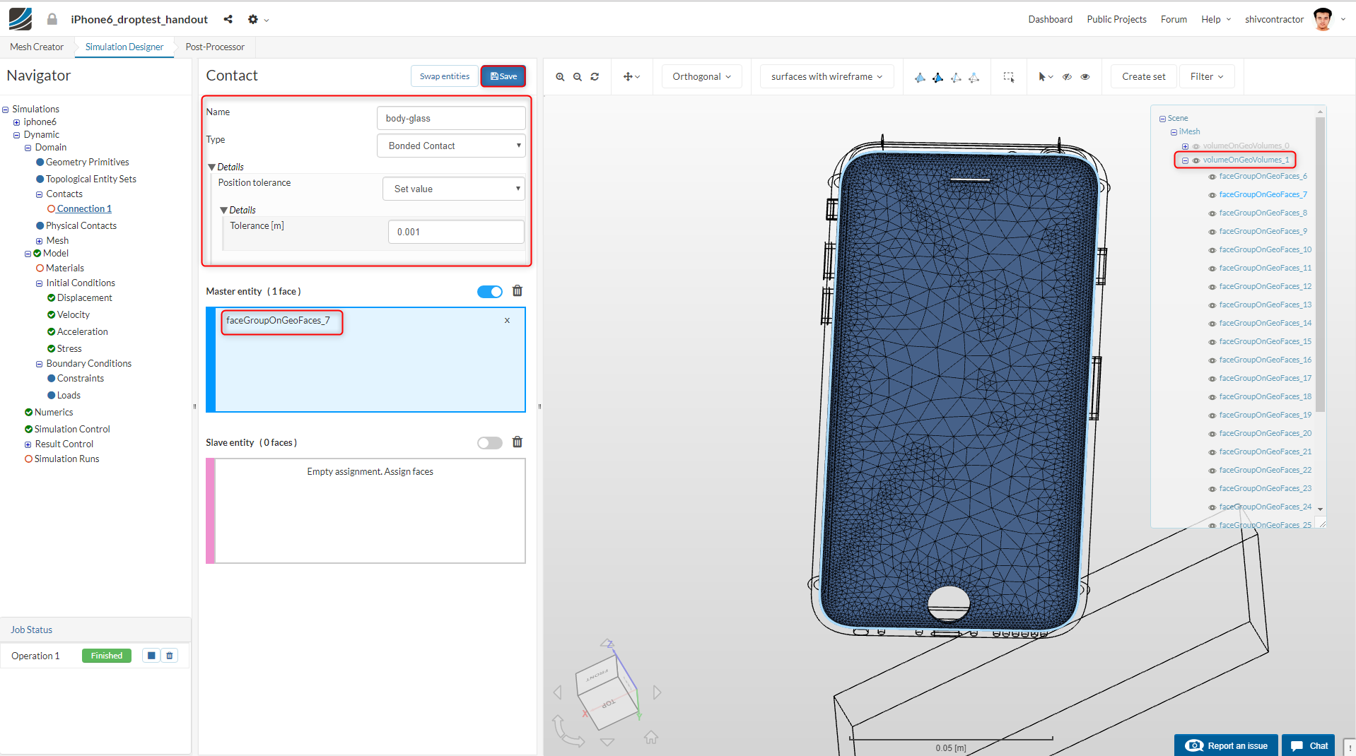
To assign the slave entity, hide all the volumes apart from volumeOnGeoVolumes_3.
Select the surface on the body in contact with the glass (counter-part of the selected master entity) and assign it as the slave entity.
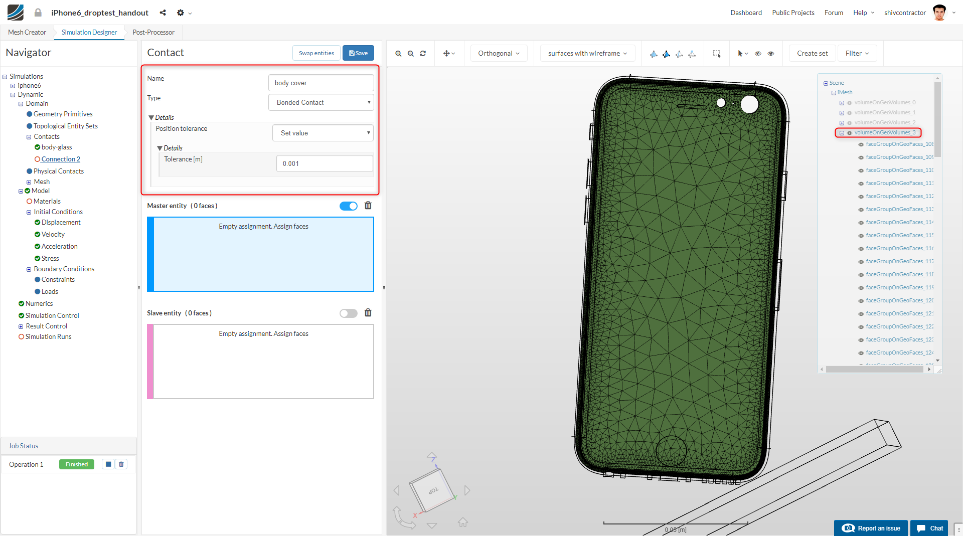
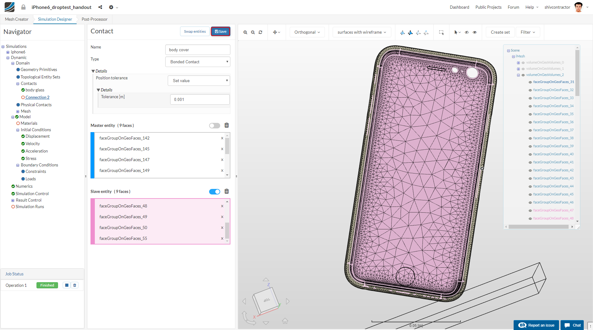
To create new contact, right-click on Contacts in the Navigator and select Add Contact Constraint.
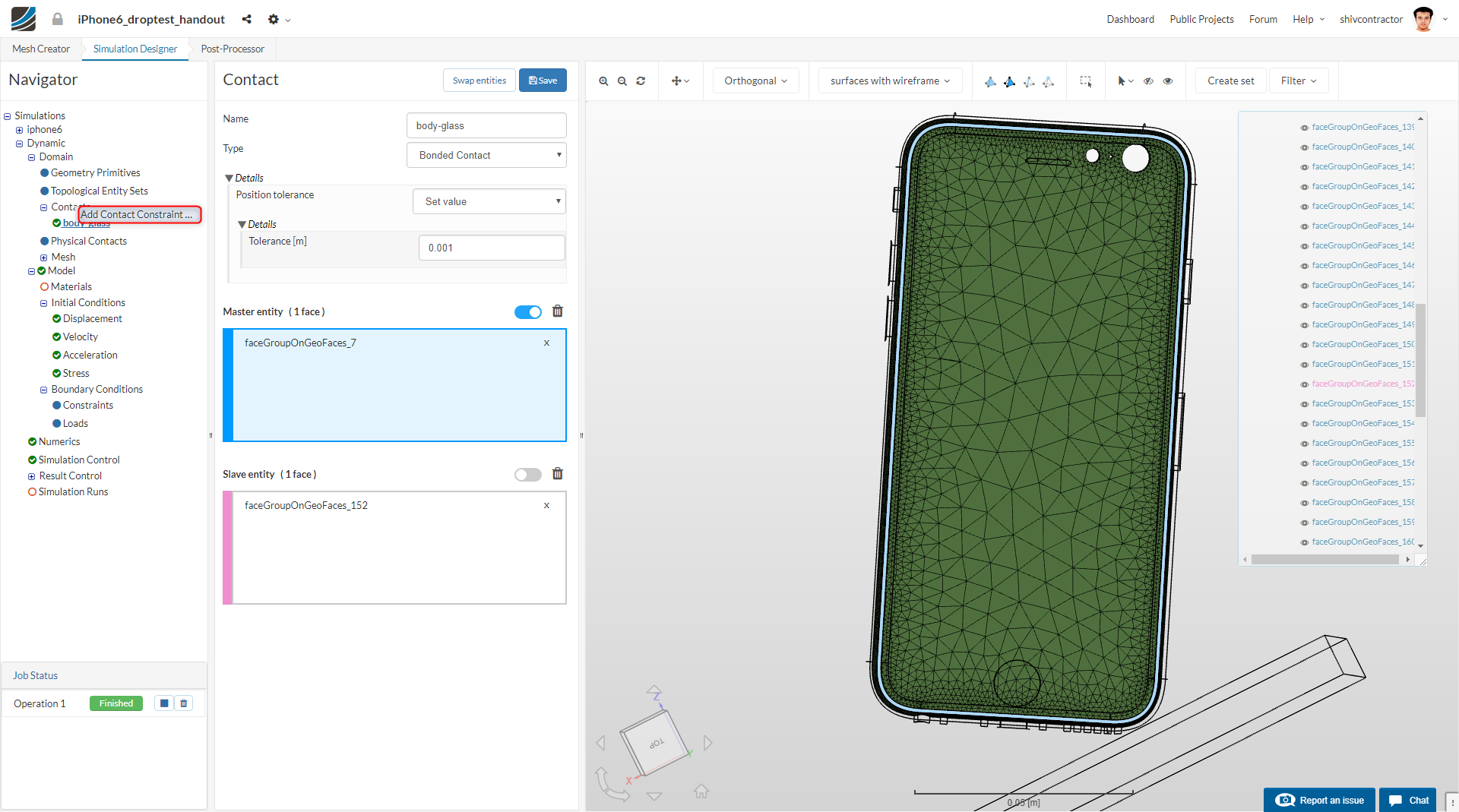
This new contact is the body-cover interface. Select the 9 faces on the outer side of the body as the Master Entities. Make sure you confirm your selections with the ones in the figure below.
Further, select the 9 faces on the inner side of the cover as the Slave Entities.
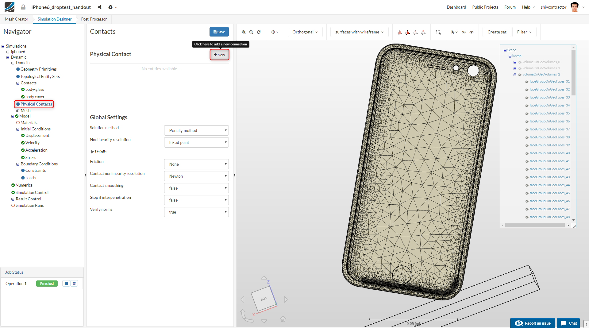
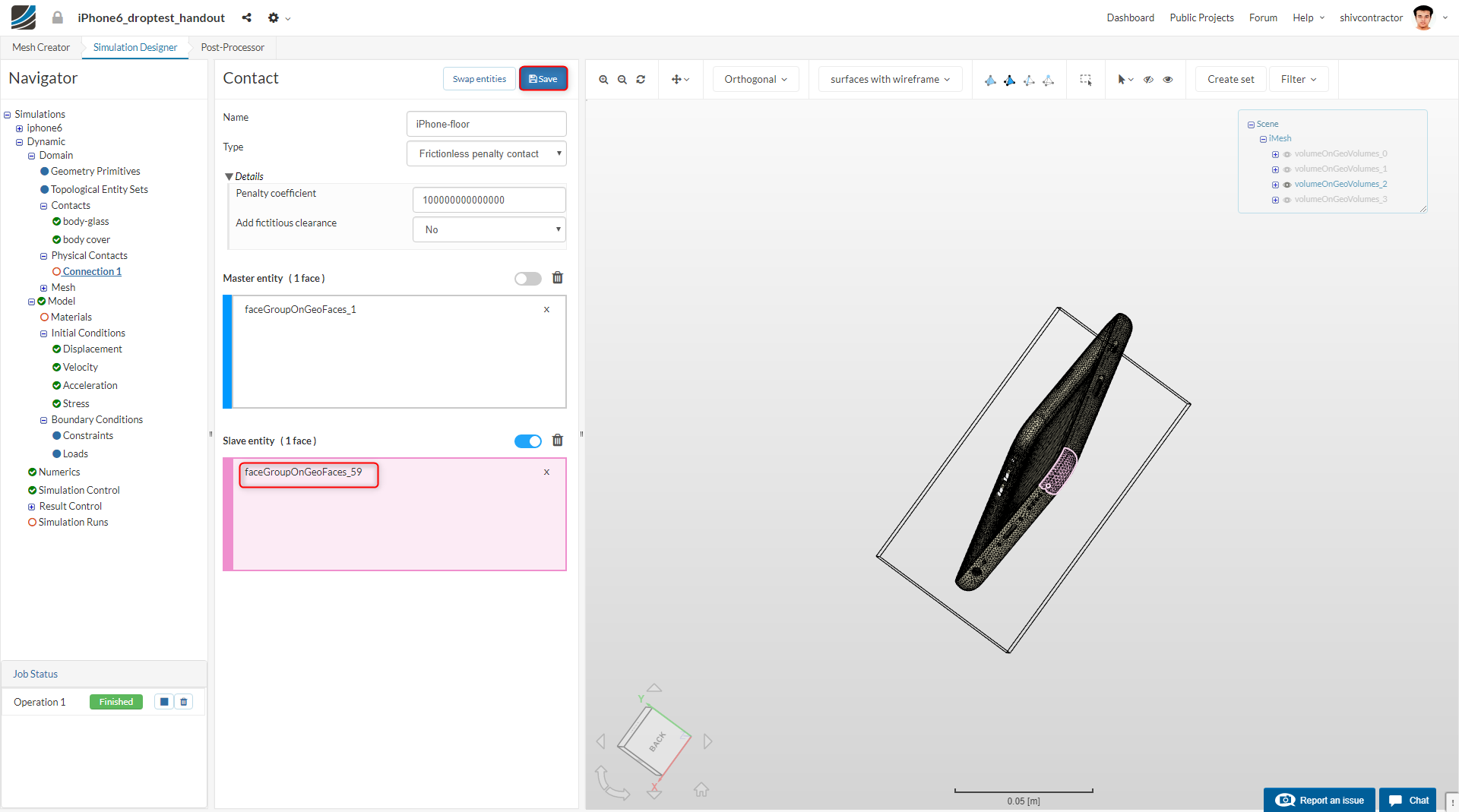
The contact between the iPhone and the floor is defined as a friction-less physical contact. Choose Physical Contacts in the Navigator, and create a New physical contact.
Select the type of contact as Frictionless Penalty Contact and increase the Penalty coefficient to 100000000000000 (10e+14). The upper surface of the ground (surface in contact with the iPhone) should be assigned as the Master entity.
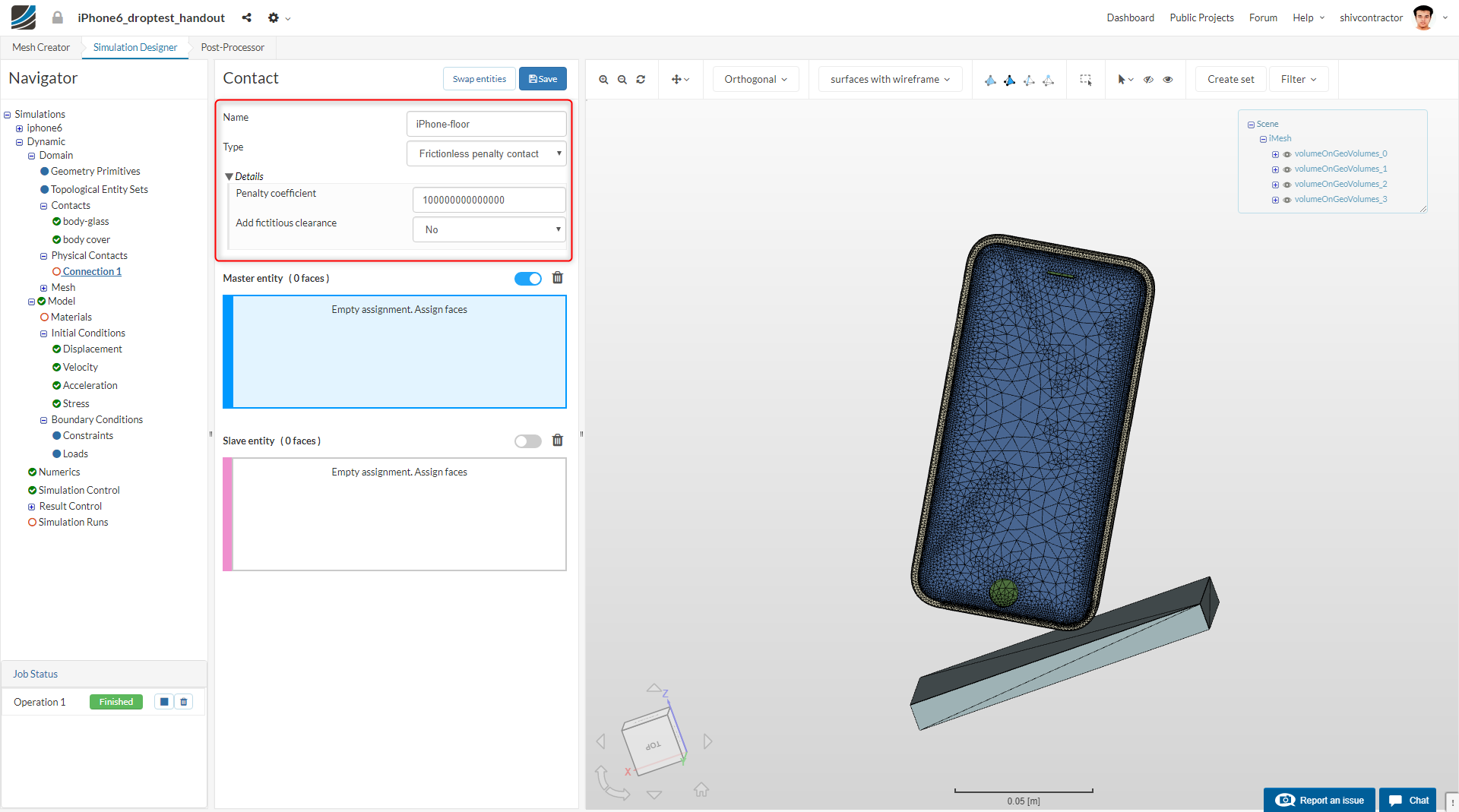
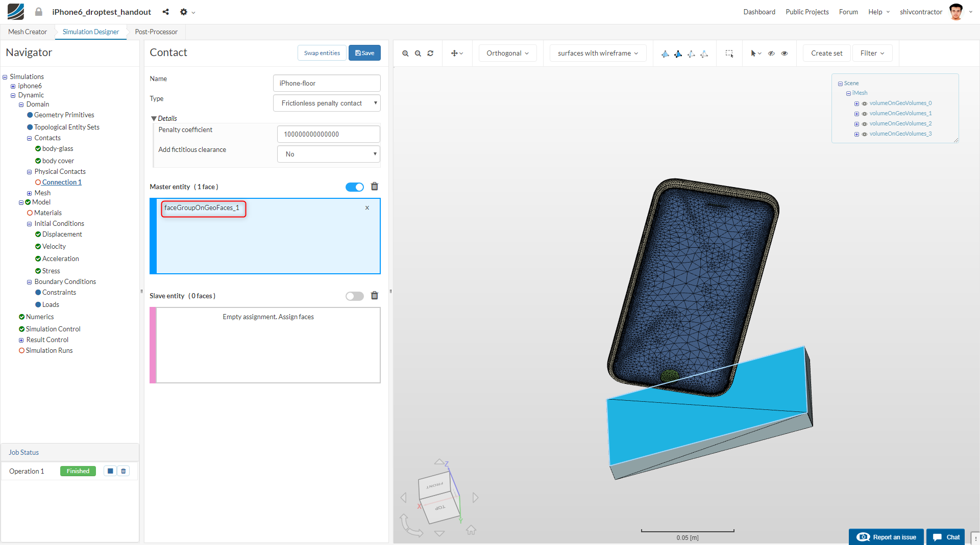
The lower part of the cover (in contact with the ground) is to be assigned as the Slave Entity.
Material Selection
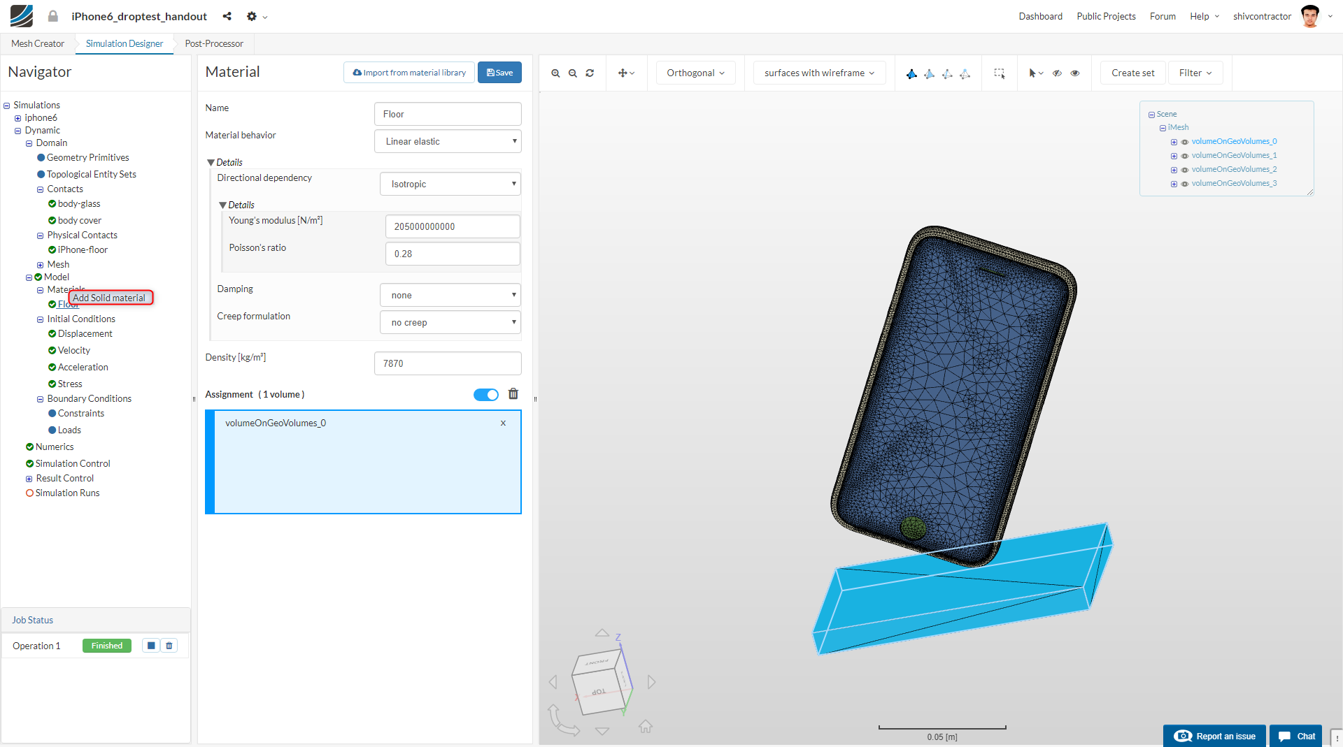
Choose the Materials option in the Navigator and click New.
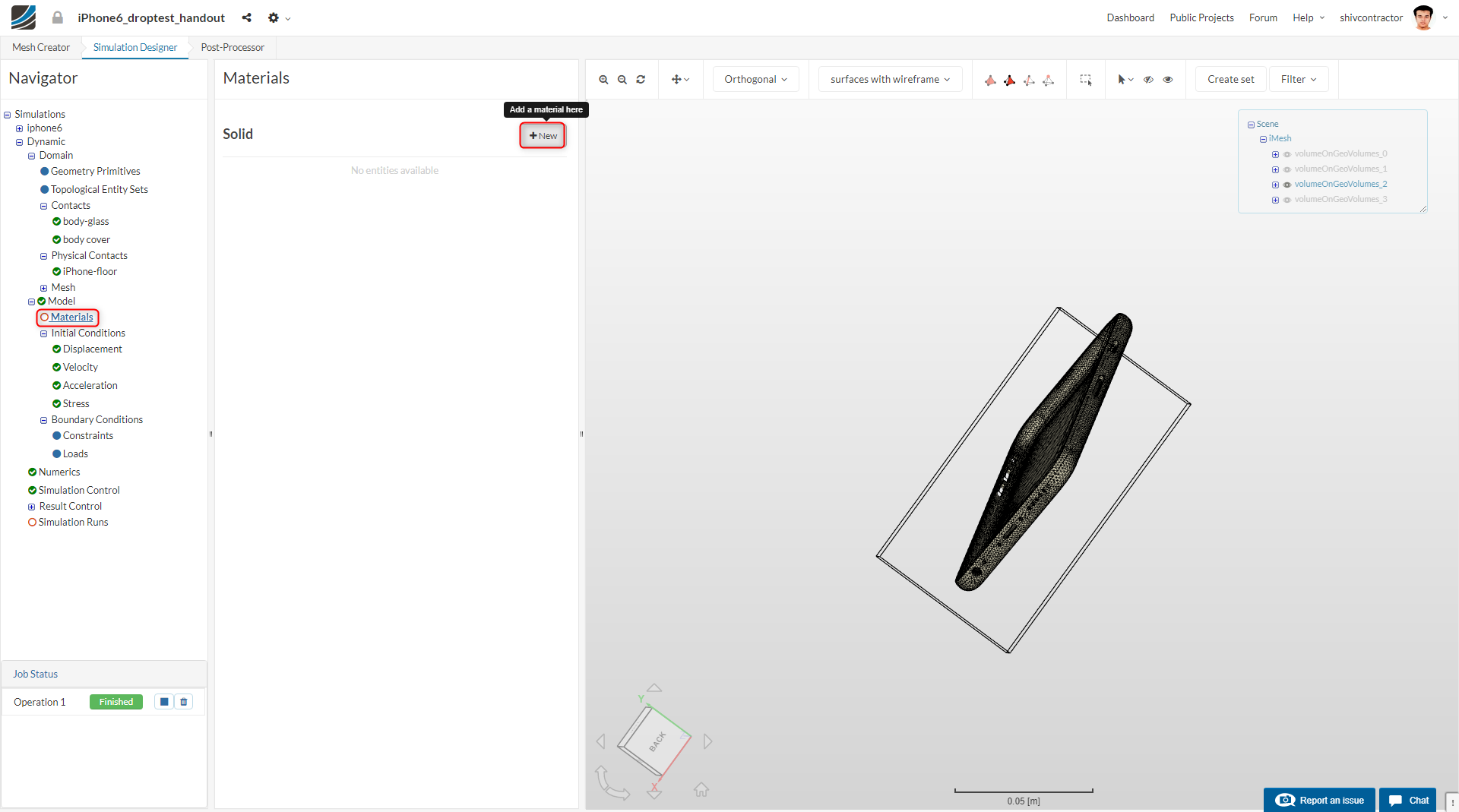
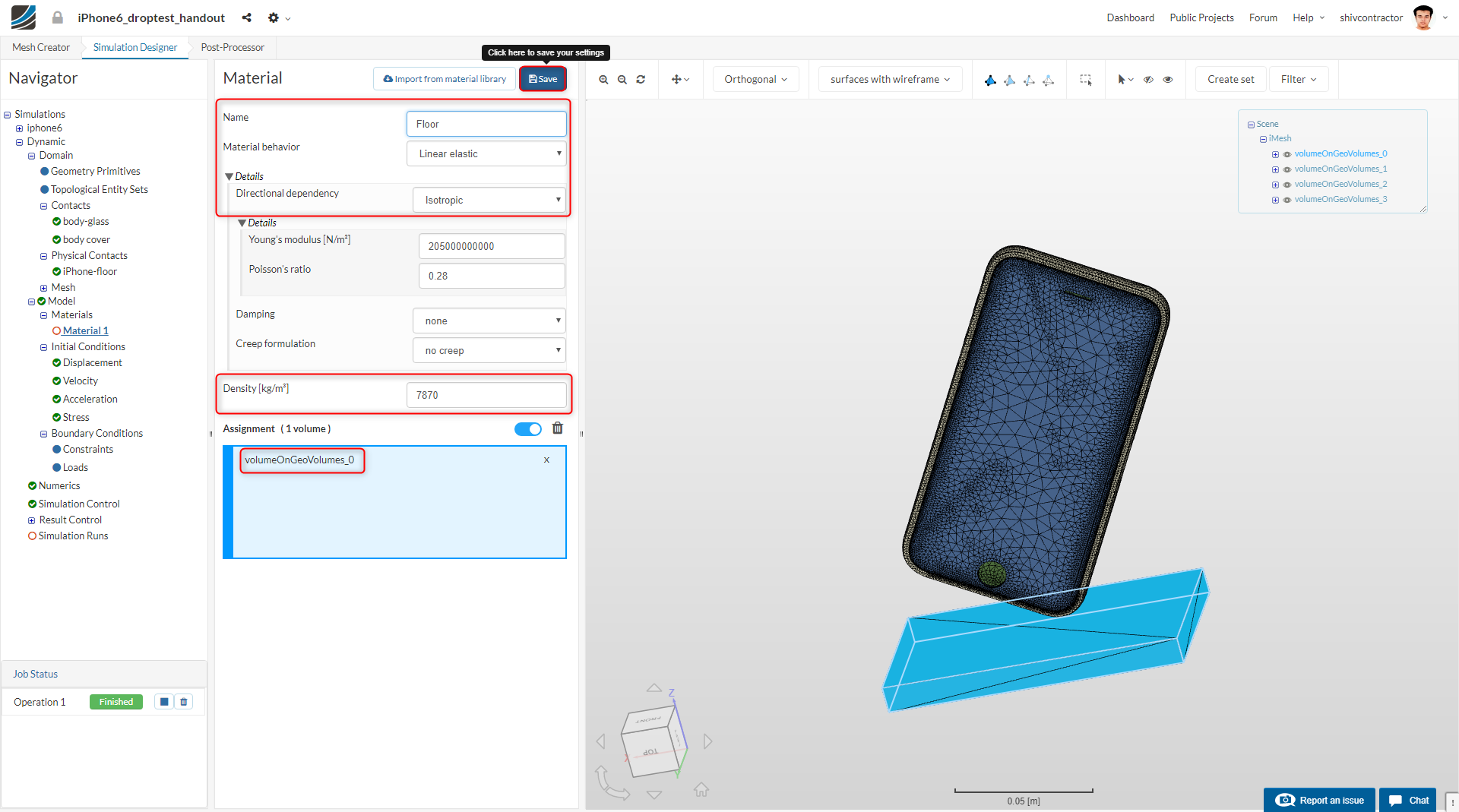
Since the material of the Floor does not play a part in the simulation results, no changes are needed here. To avoid confusion, you may rename Material 1 to Floor.
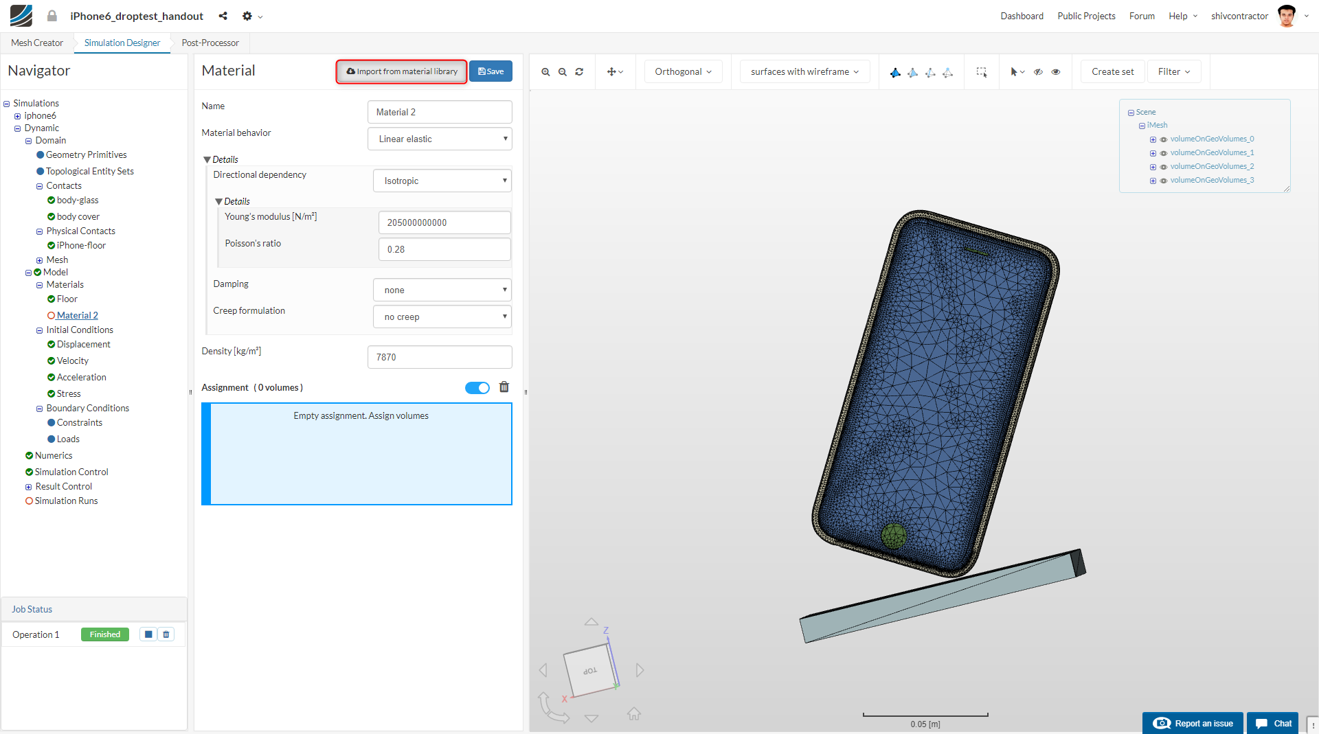
Now, let us proceed to add material to the iPhone body. To add a new material, right click on Materials in the Navigator and click on Add Solid material.
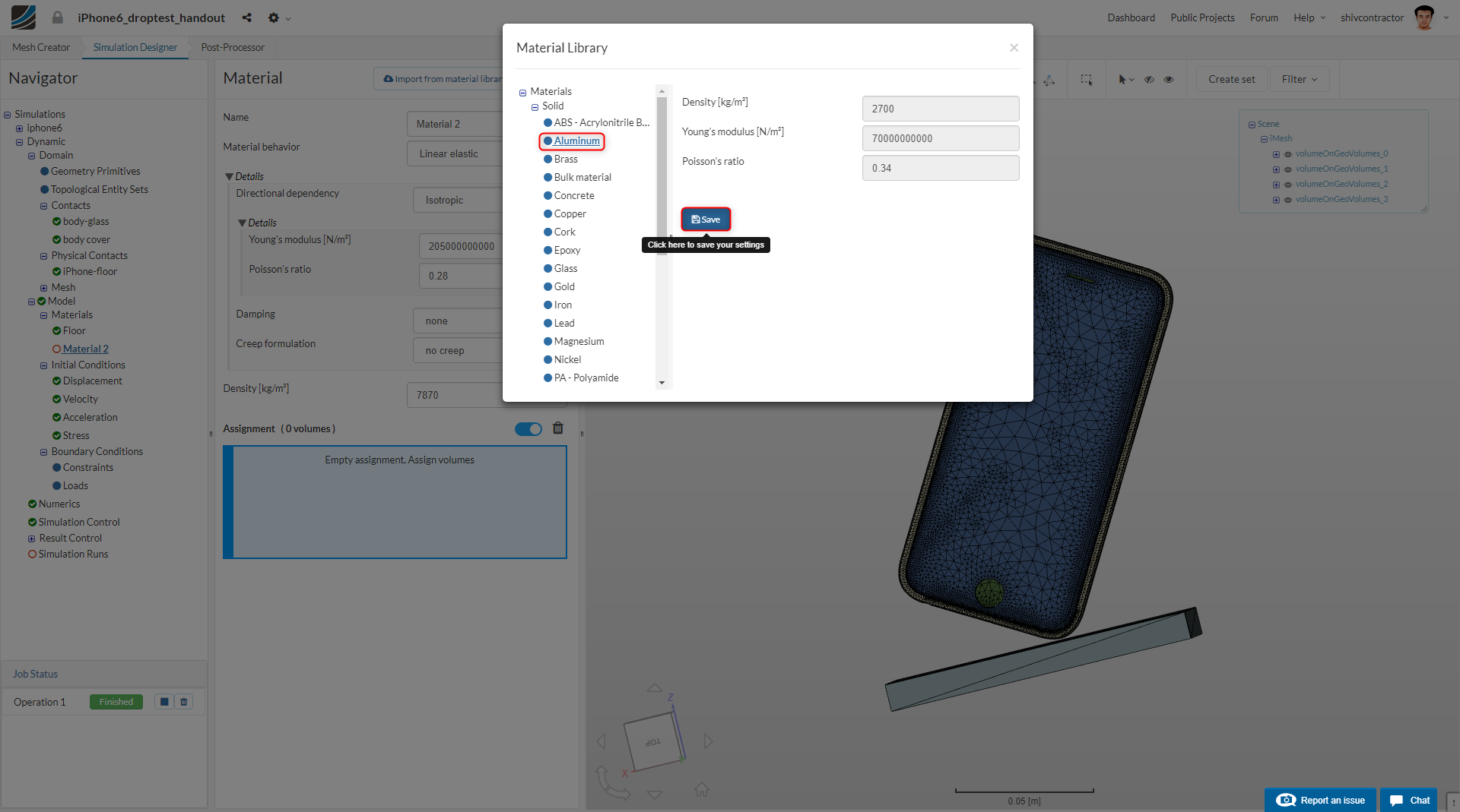
We need to assign the material Aluminum to the iPhone body. To do this, click Import from material library select Aluminum from the list of materials displayed in the library.
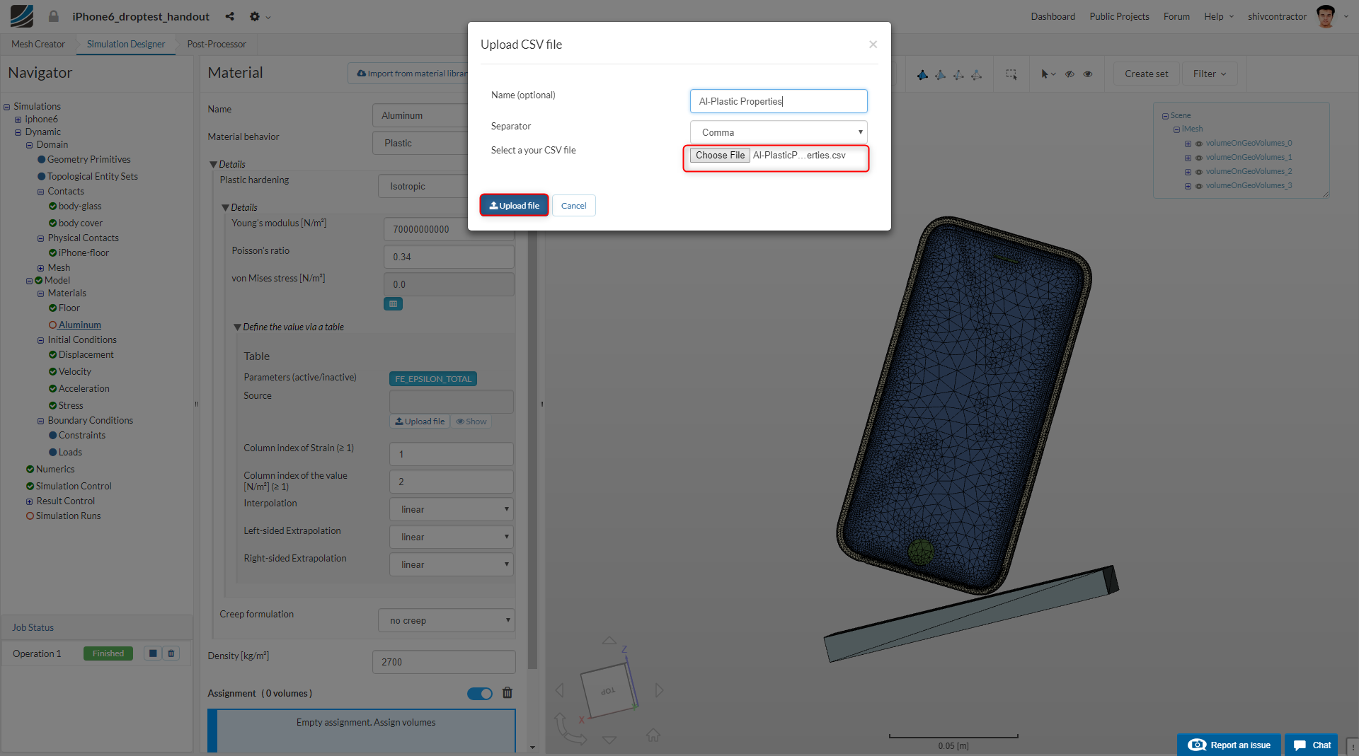
Our goal is to determine whether the drop causes the iPhone to plastify, i.e., create a dent on it. Thus, set Material behavior to Plastic. The plastic behavior of the material is defined with a .csv file containing the stress and strain data. The prepared CSV file can be downloaded from here.
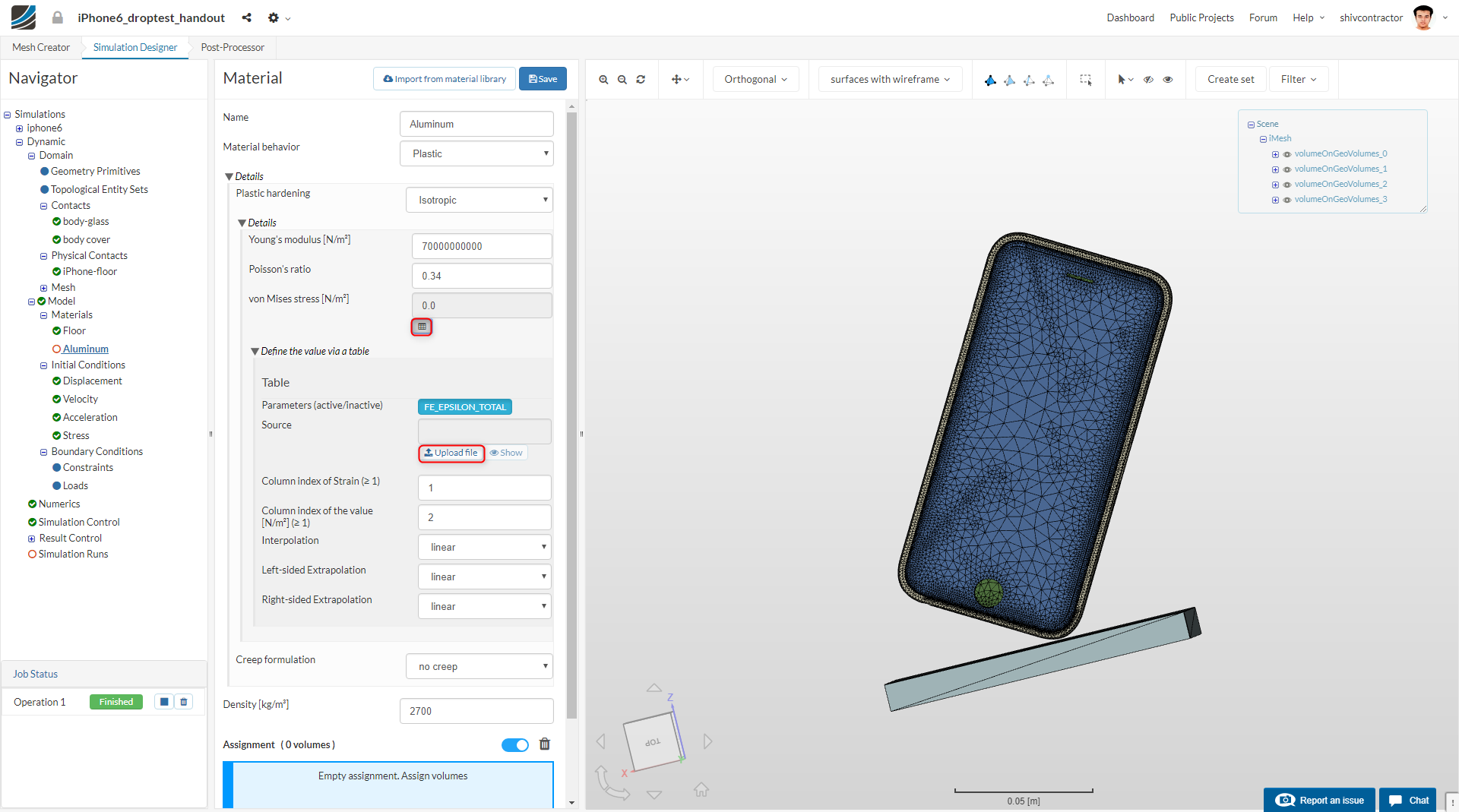
A dialogue box will be displayed. Click choose file and select the file you downloaded from the link above.
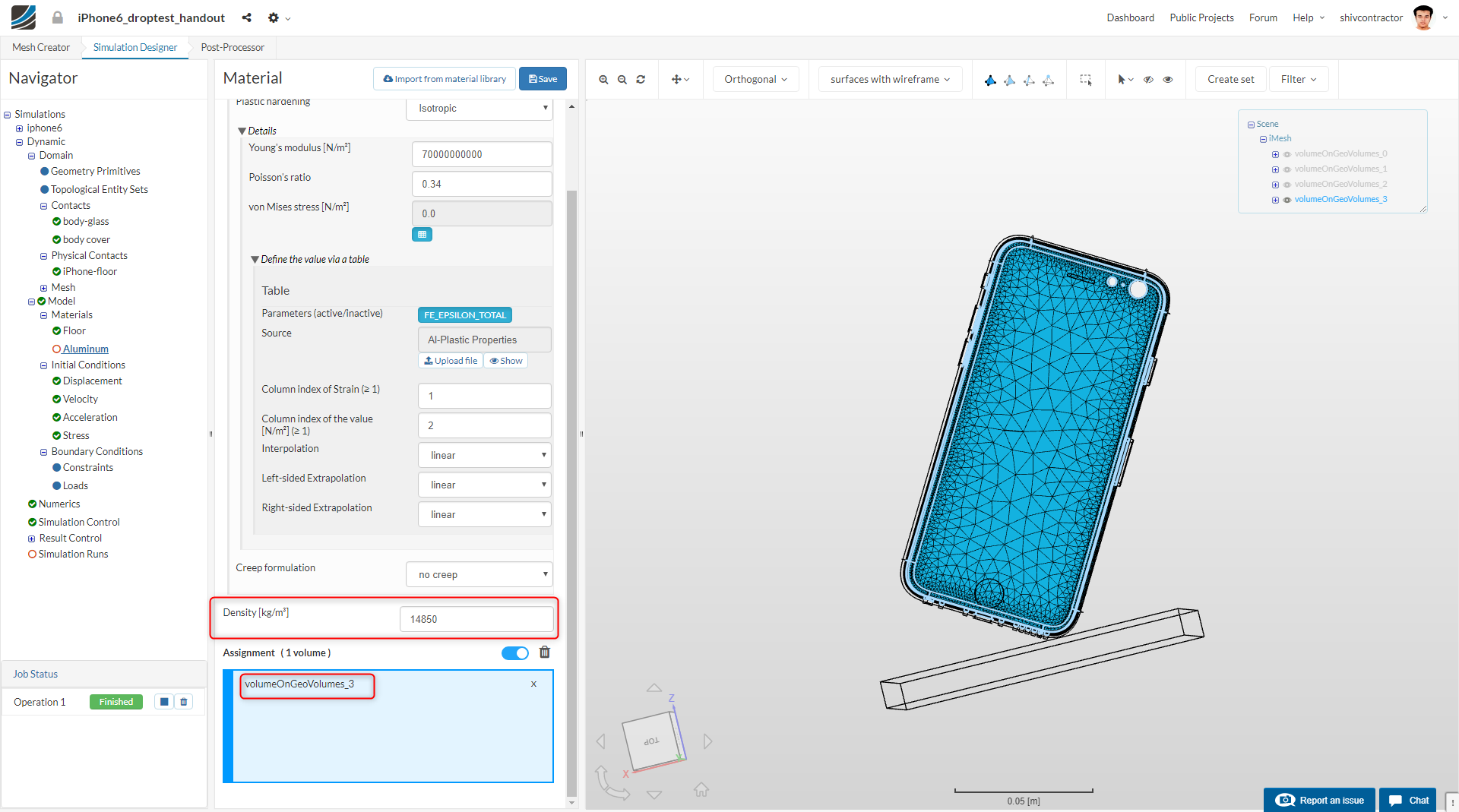
You may note that we are simulating the iPhone without its internal electronics.Therefore, the material density is modified in order to match the weight of the iPhone (172g). Let us proceed to mapping this material to the iPhone body.

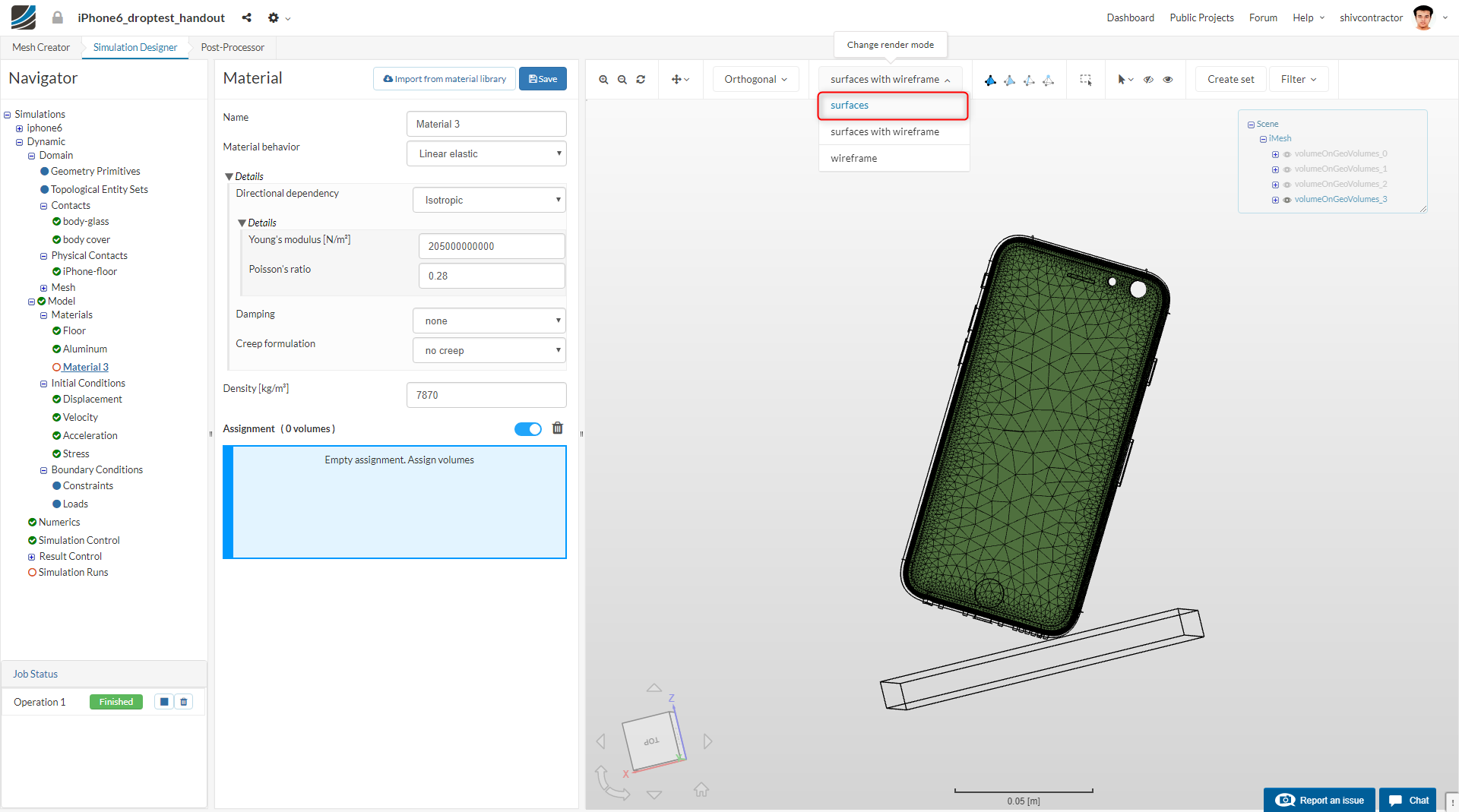
For better visualization, change the rendering mode to surfaces.
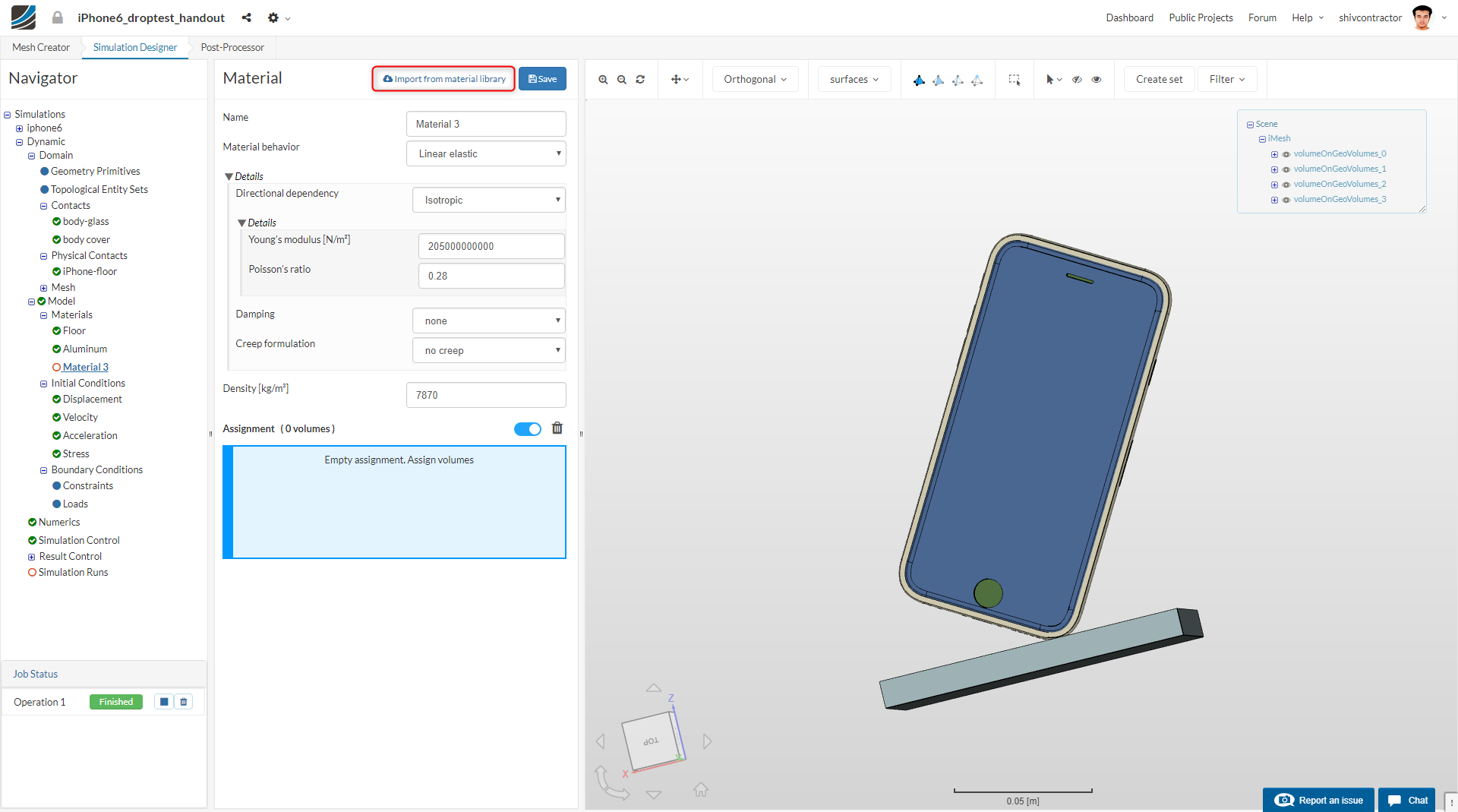
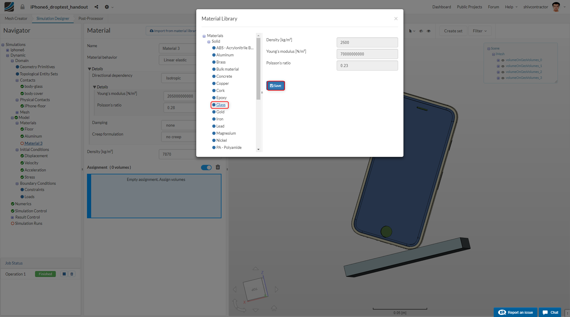
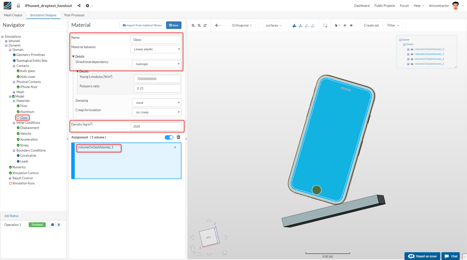
Now, we need to assign the material Glass. Following the procedure shown earlier, add new material and import Glass from the Material Library. Take reference from the images shown below:
We now proceed to add material to the iPhone cover. To add a new material, right click on Materials in the Navigator and click on Add Solid material.
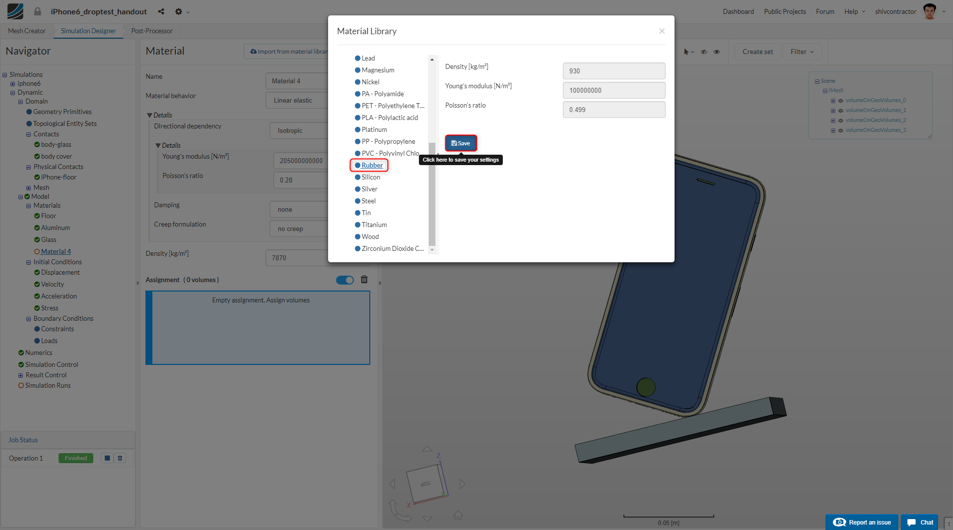
You may now import the material Rubber from the material library by clicking on Import from material library and selecting Rubber. The Material behavior is to be set to Hyperelastic, a more accurate representation of the physical behavior of rubber under loading.
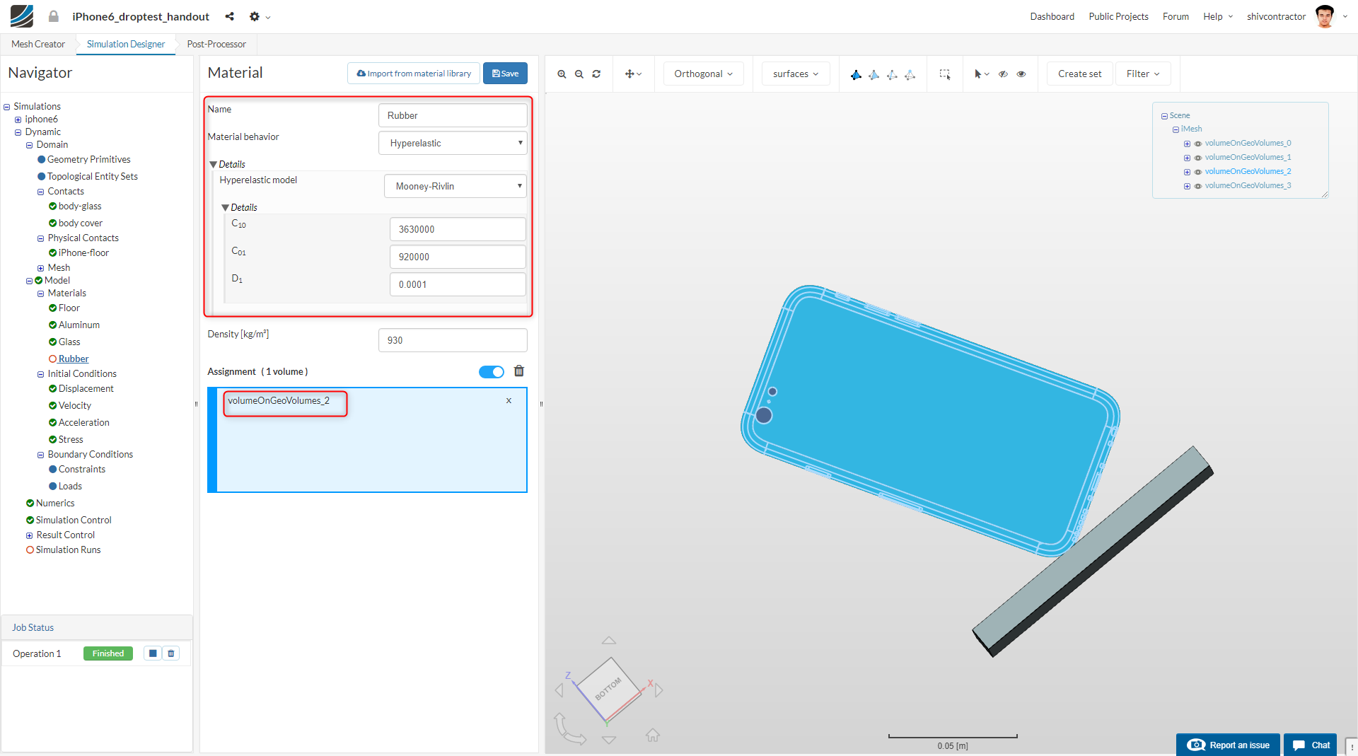
Assign this material to the iPhone cover by selecting it from the viewer and clicking on Save.
Assigning Constraints and Loads
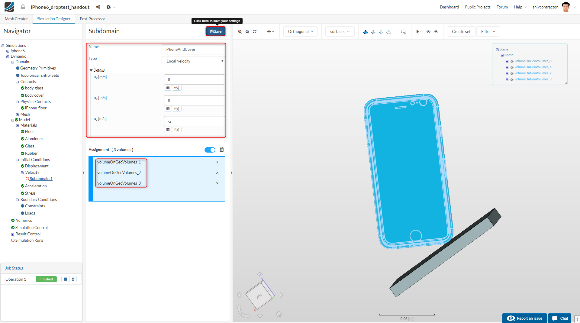
Previously, we had calculated that the velocity of the iPhone at impact is 2m/s. Therefore, let us apply an initial condition of 2 m/s to the iPhone.
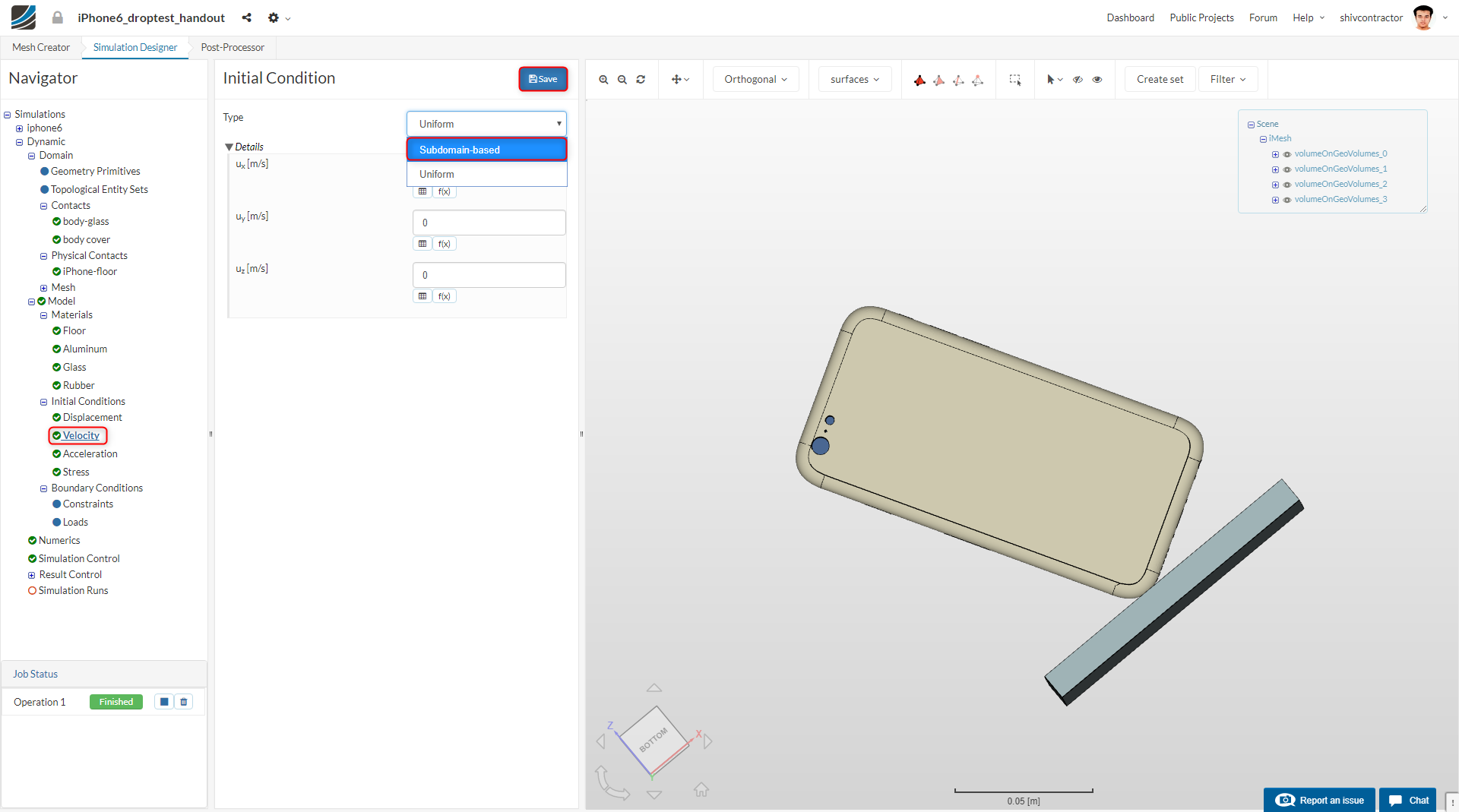
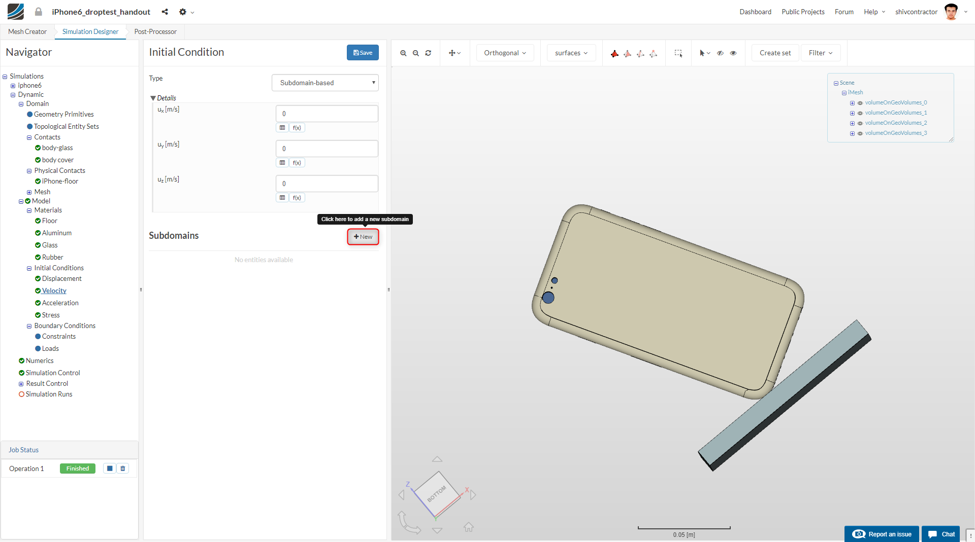
Select all the three volumes and assign them the velocity of 2 m/s. Since the iPhone is falling in the -z direction, the velocity will be assigned a negative sign.
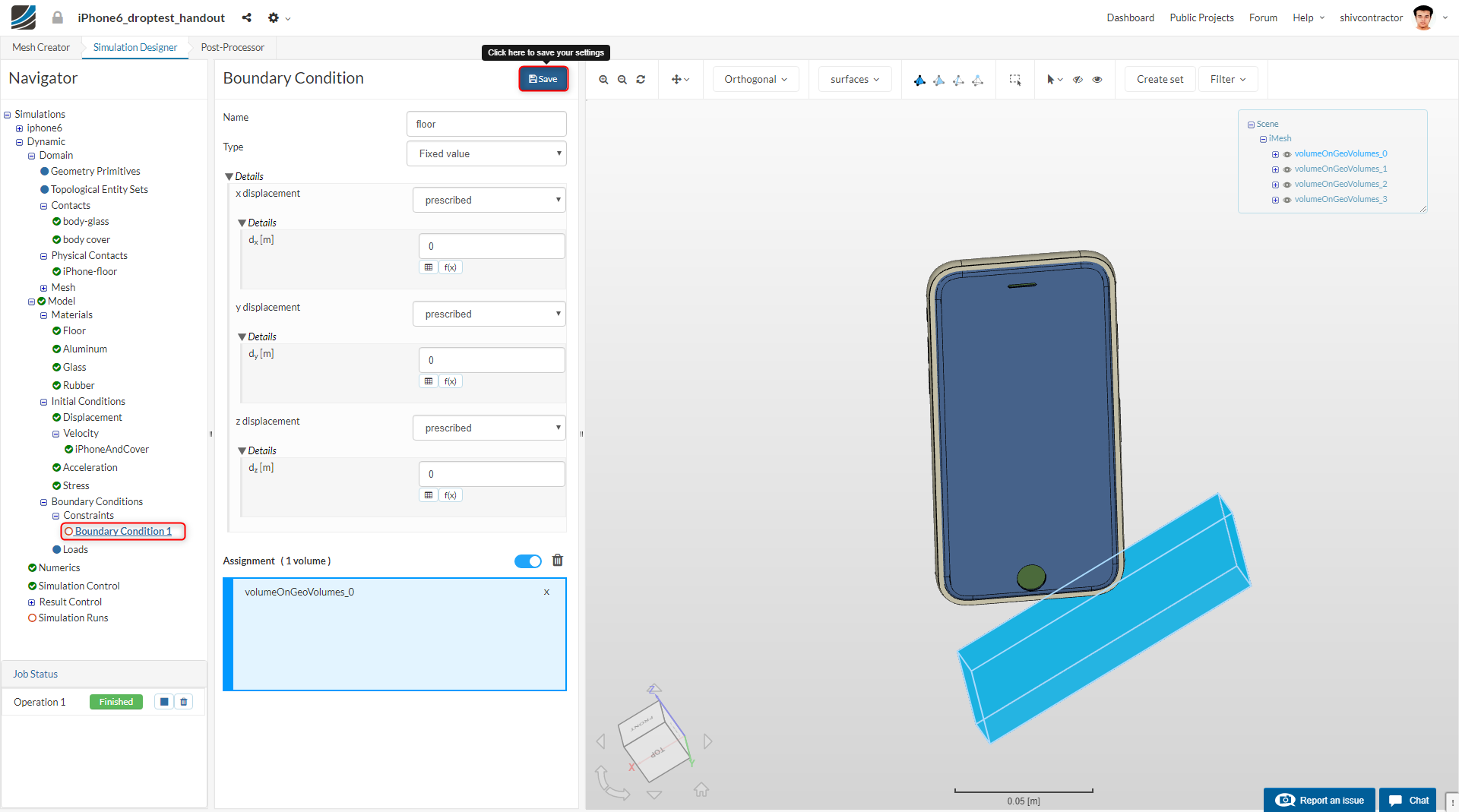
Proceeding to add constraint boundary conditions, click on Constraints and then New.
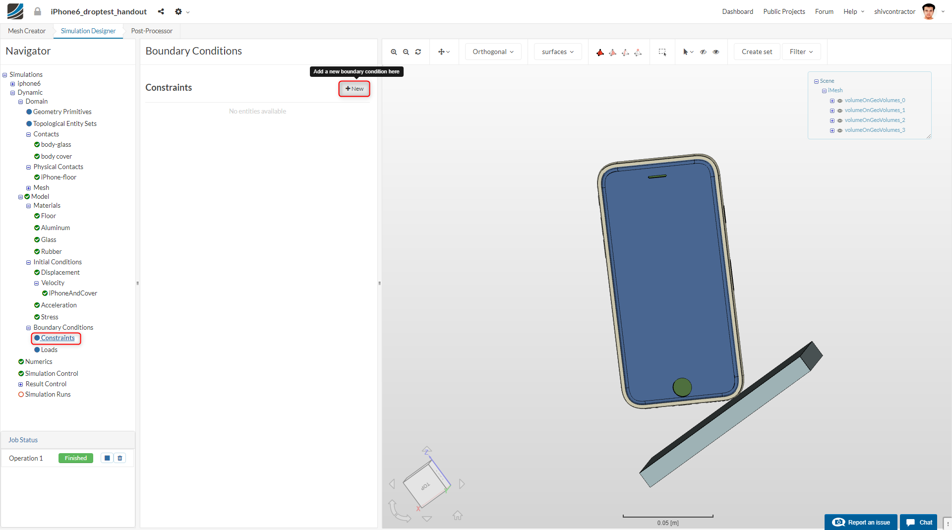
Moving further, let us model the floor:
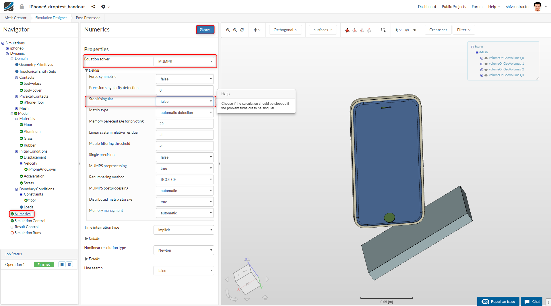
Numerics
Click on Numerics in the Navigator and select the solver MUMPS. Set the parameter Stop if singular is set to False. This enables the solver to avoid divergence at the initial iterations.
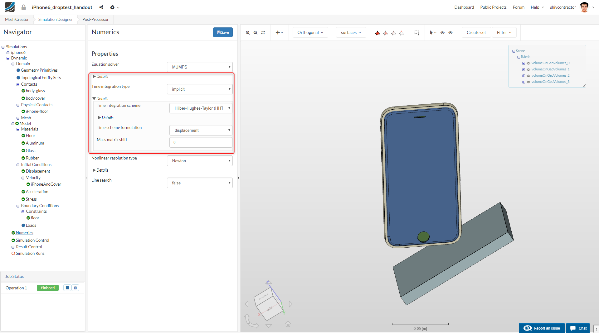
Change the Time integration scheme to Hilber-Hughes-Taylor (HHT).
Next, change the Convergence criteria type to Absolute.

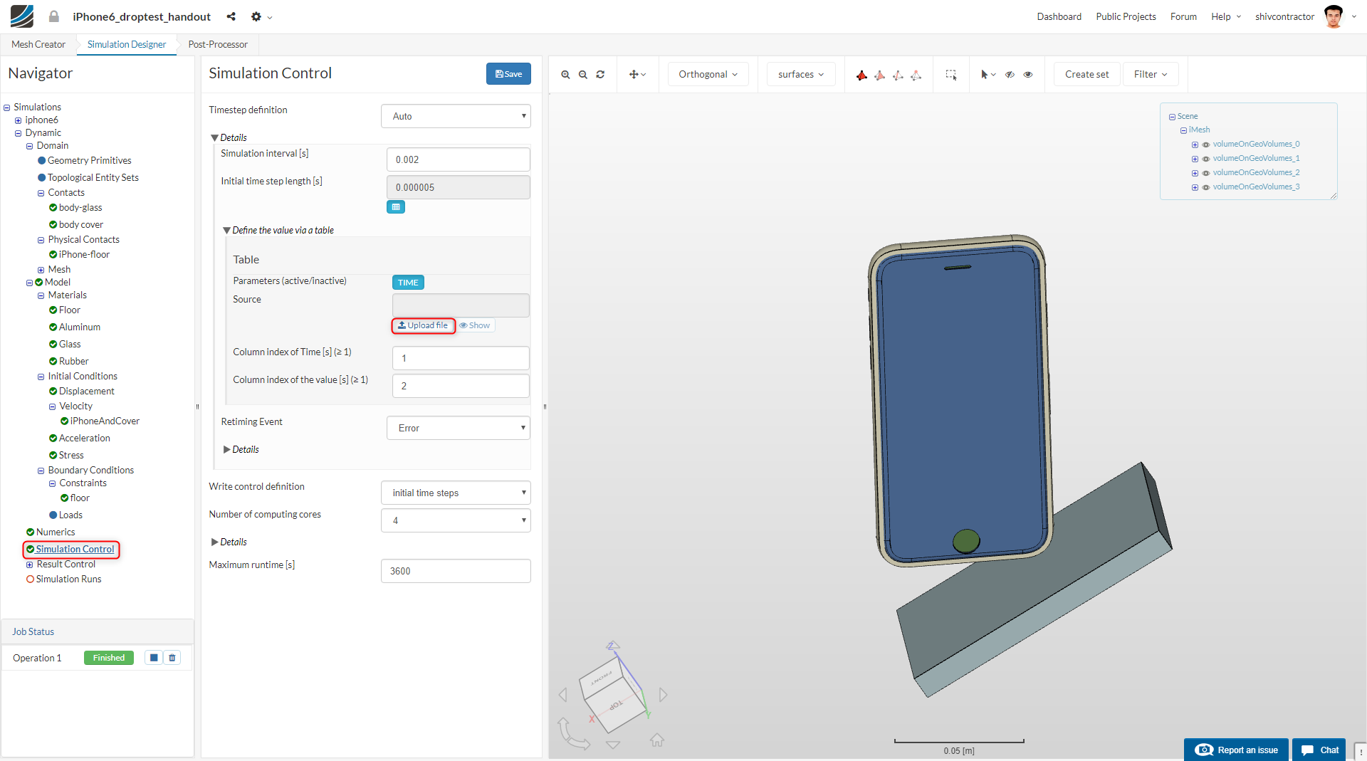
Simulation Control
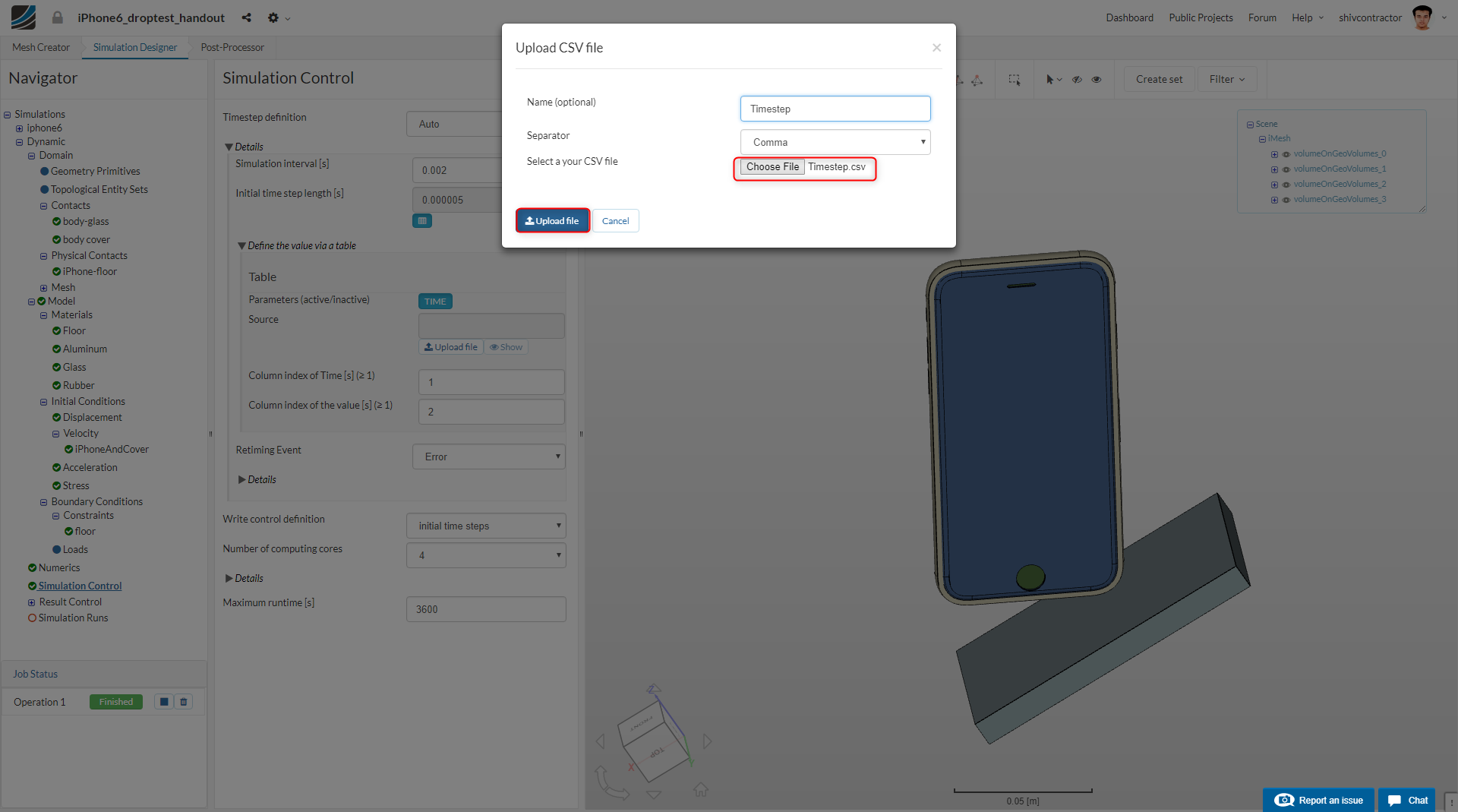
You may now define the Simulation Control. Set the Simulation Interval to 0.002 and the Initial timestep length to 0.000005. A file that defines a ramped time step is to be uploaded. This file makes our simulation run quickly until the iPhone reaches the ground and reduces the time step on impact. To upload the files, use the link below and follow the instructions as shown in the below images.
https://docs.google.com/spreadsheets/d/1fbSRvwUirU957oD8-YArJyOS7g8VKBEVRzHAWayvuSs/edit?usp=sharing
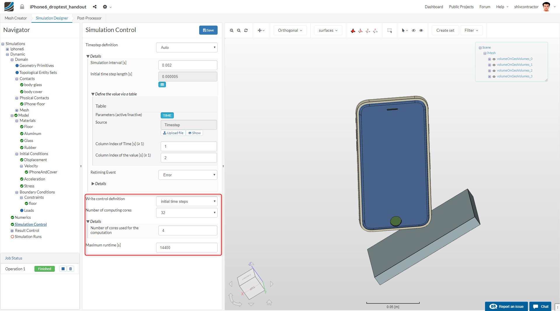
The uploaded file will appear in the Navigator Pane. Now, set the Number of computing cores to 32 and the Number of cores used for computation to 4. Also, increase the Maximum Runtime to 14400.
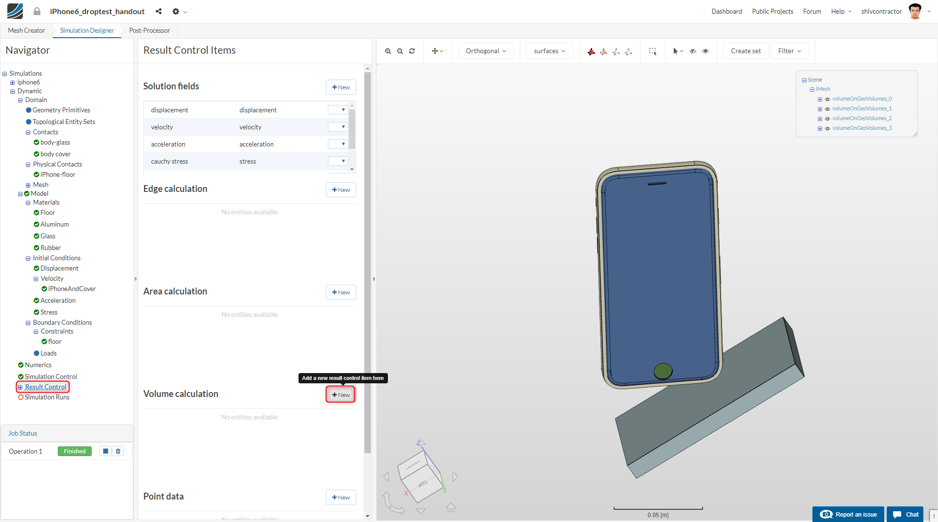
Result Control
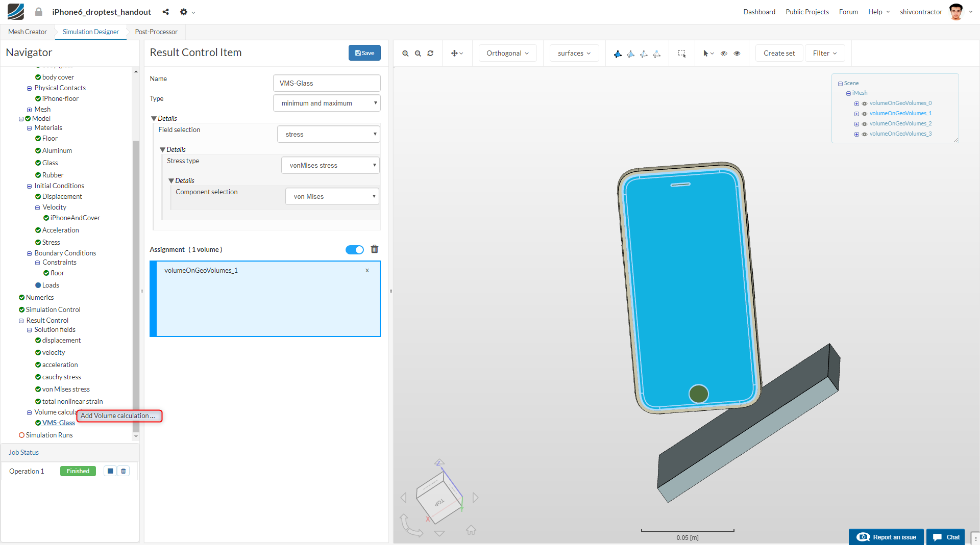
For an effective analysis of the results, it is imperative to monitor the solution fields with Result Control Items. In our case, we do it for the glass.
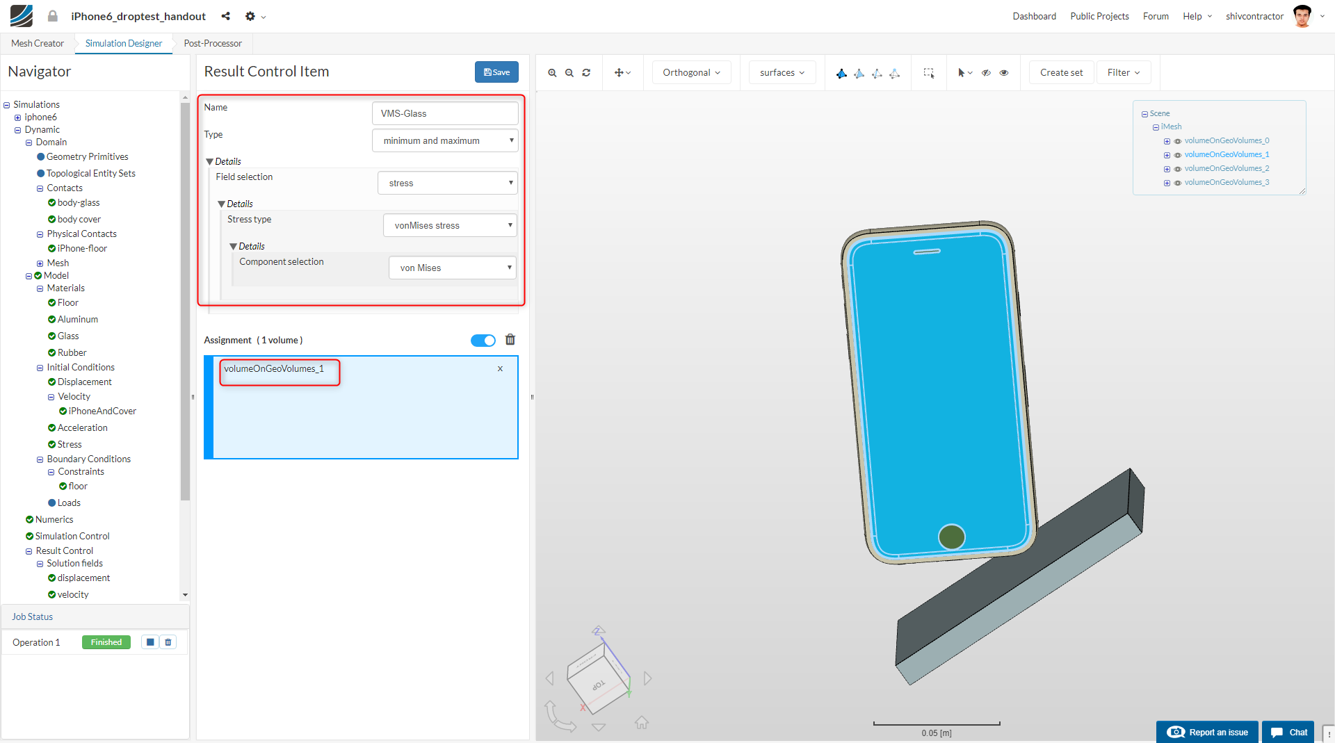
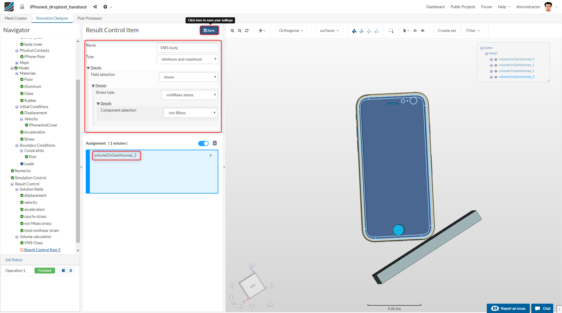
The second result control item is the body (Volume Calculation). You can add a new result control item by right clicking on the Volume Calculation option in the Navigator and selecting Add Volume Calculation.
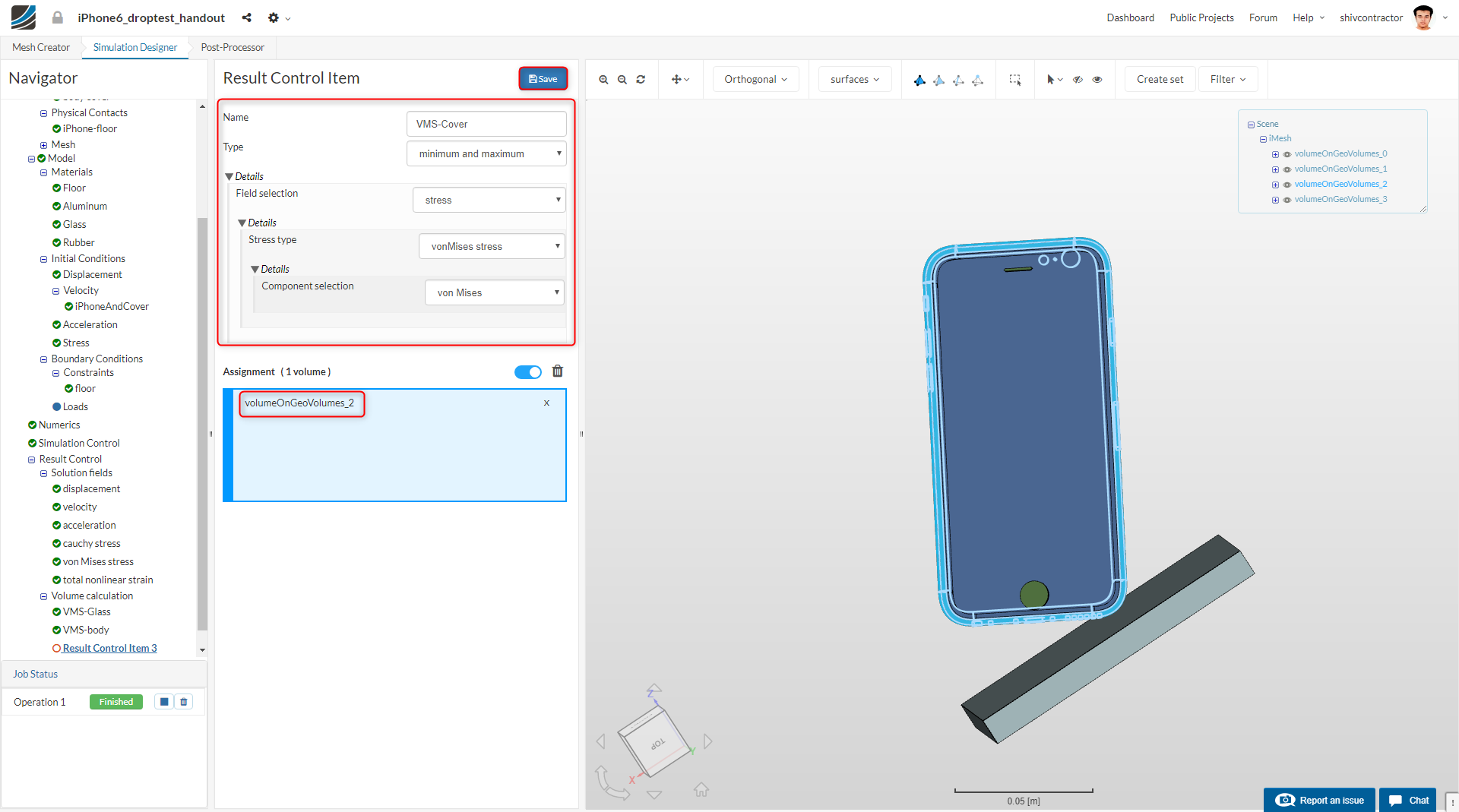
Similarly, add a third result control item and assign it to the cover of the iPhone.
Initiating the Simulation
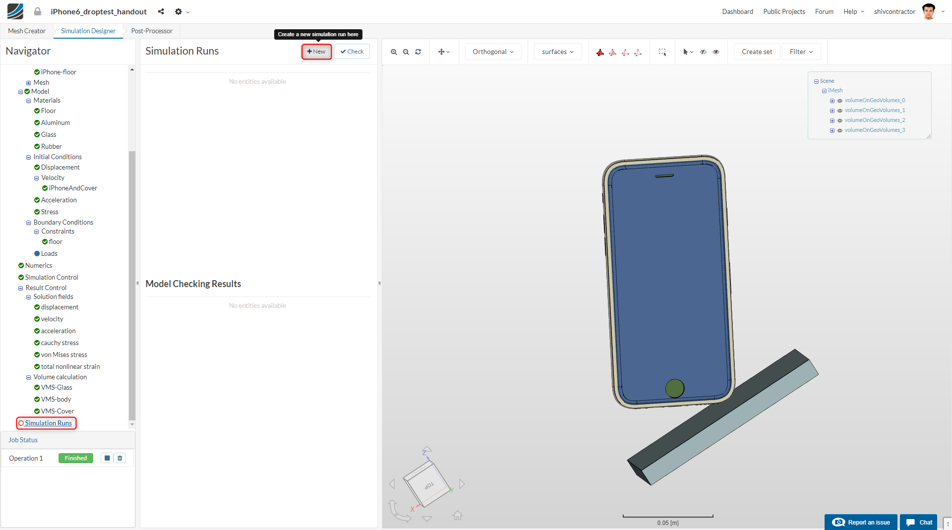
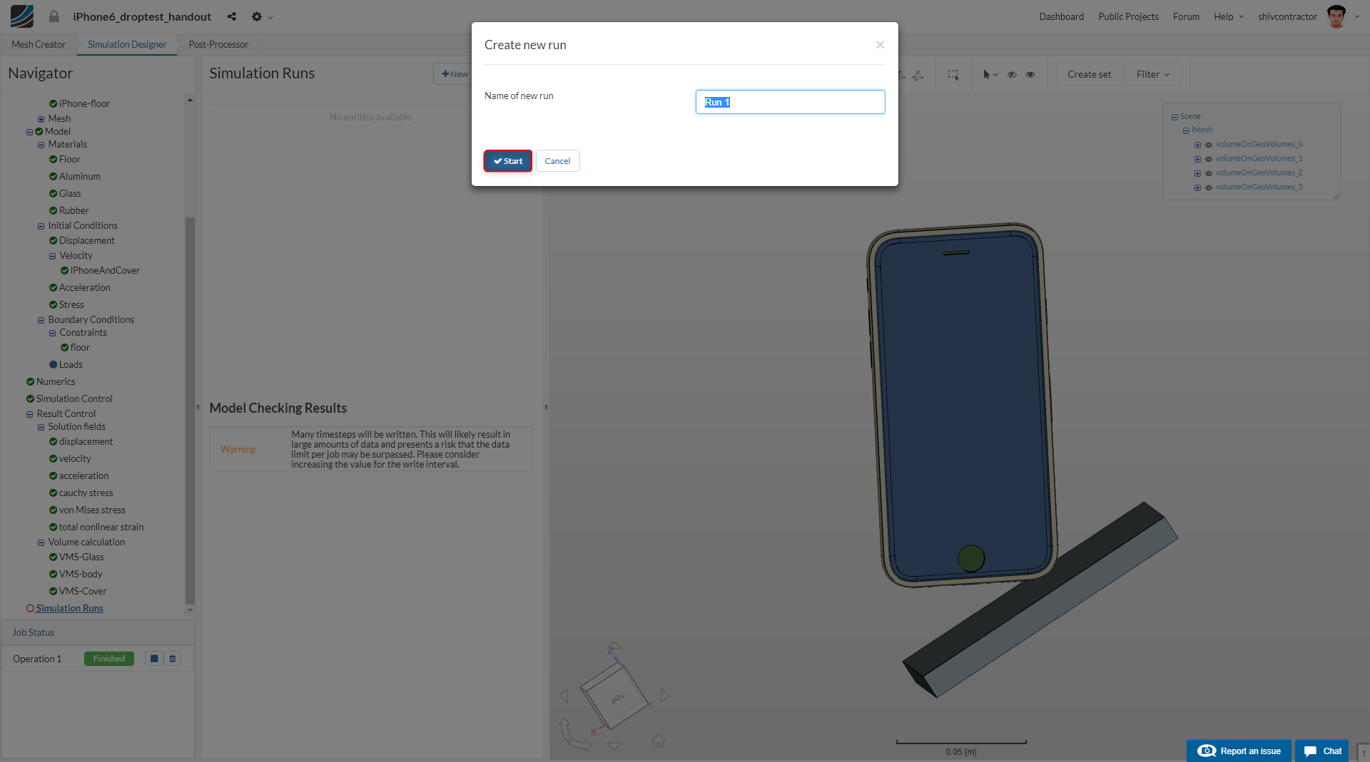
Create a new run by selecting the Simulation Runs tab in the Navigator and clicking on New.
Kindly note: You may receive the following warning when creating a simulation run:
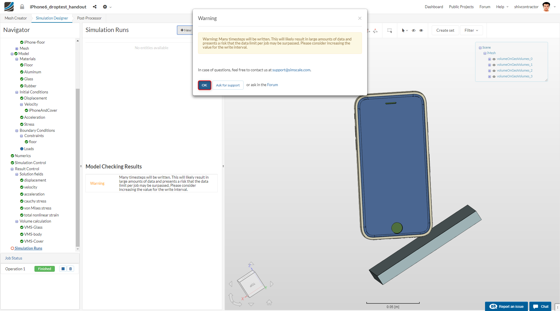
You may ignore this warning and proceed to the simulation by clicking OK.
You may Name the run as you like and Start the simulation.
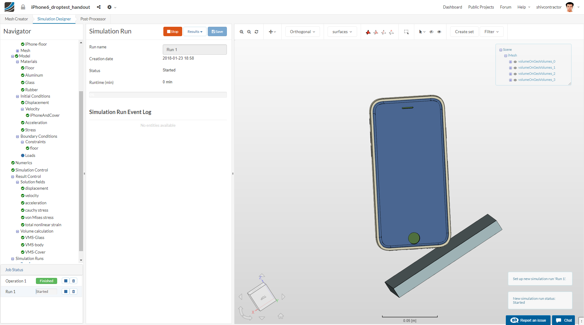
The simulation progress can be tracked in the bottom left of the viewer as shown in the figure below.
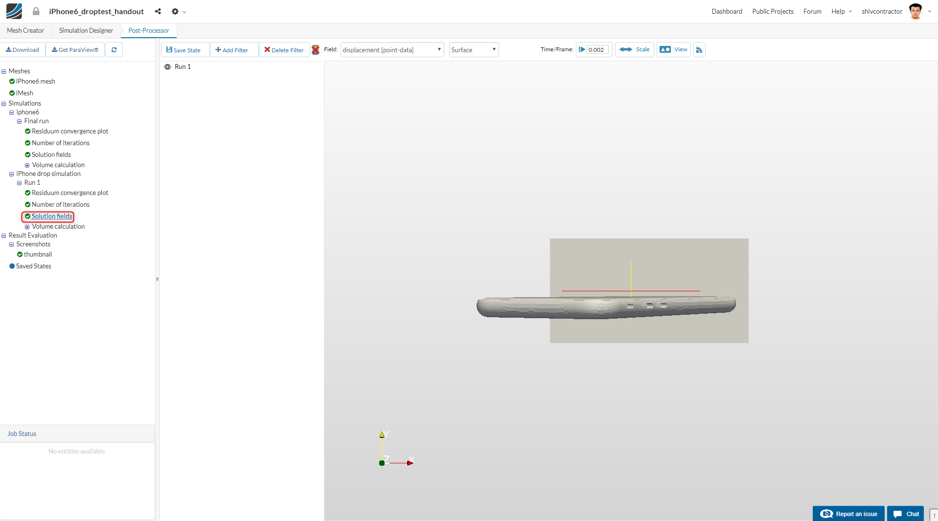
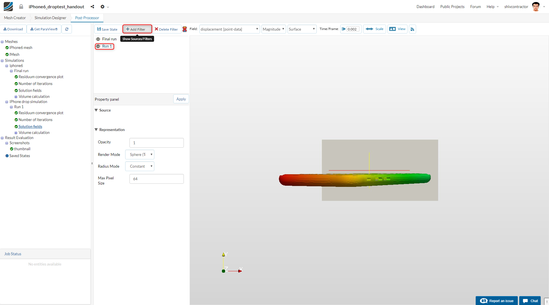
Post-Processing
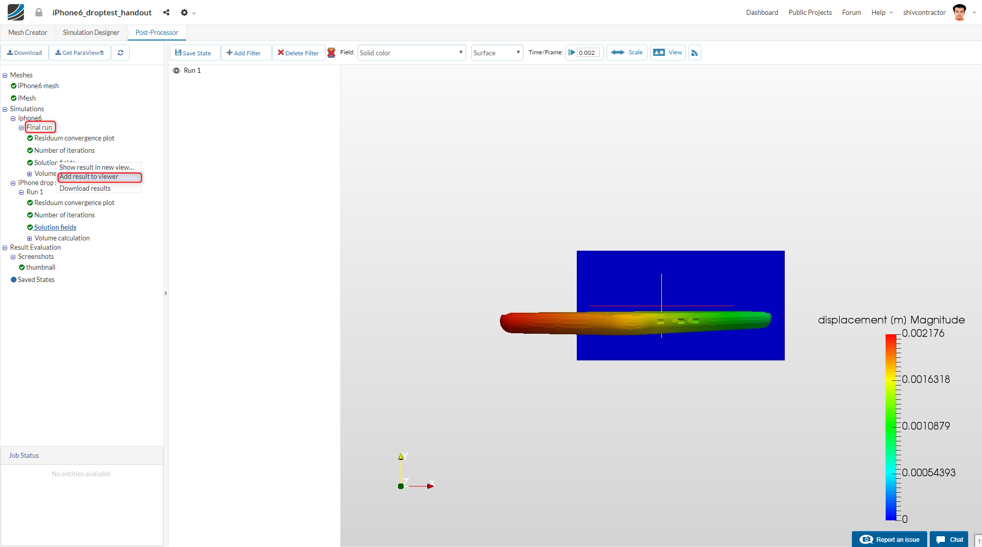
Open the Post-Processor tab from the workflow. To visualize your result in the viewer, select it in the Navigator and click on Solution Fields.
To add the provided simulation results to the viewer, right click on Final Run under iPhone6 and Add result to viewer.
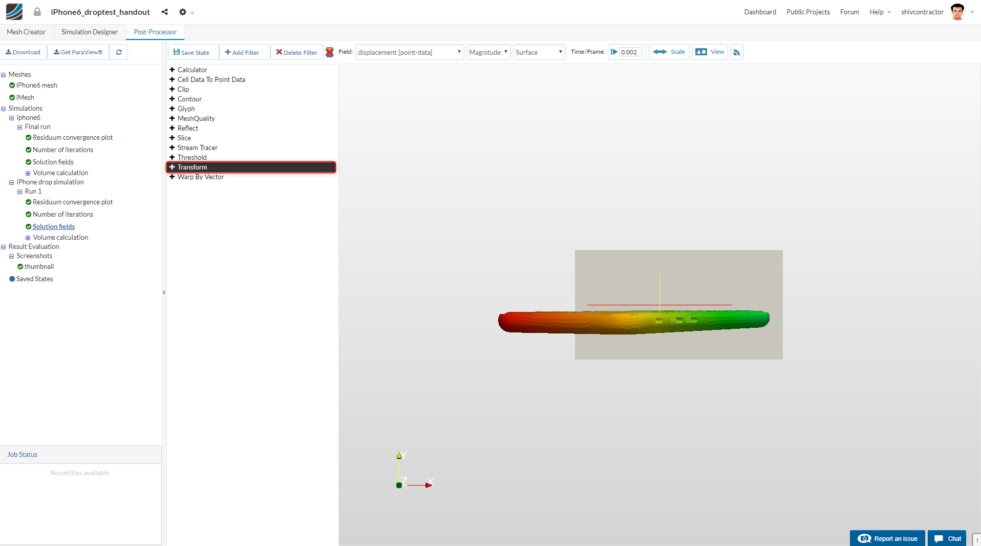
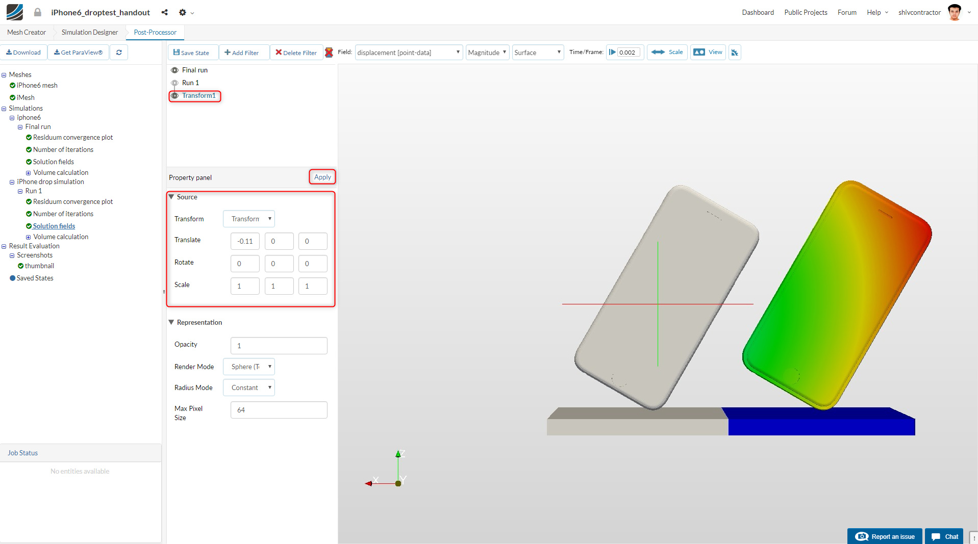
Transform filter:
The transform filter is a useful tool to qualitatively analyze two different results simultaneously. It may be added as follows:
Set the first column of Translate to -0.11 and click Apply as shown below.
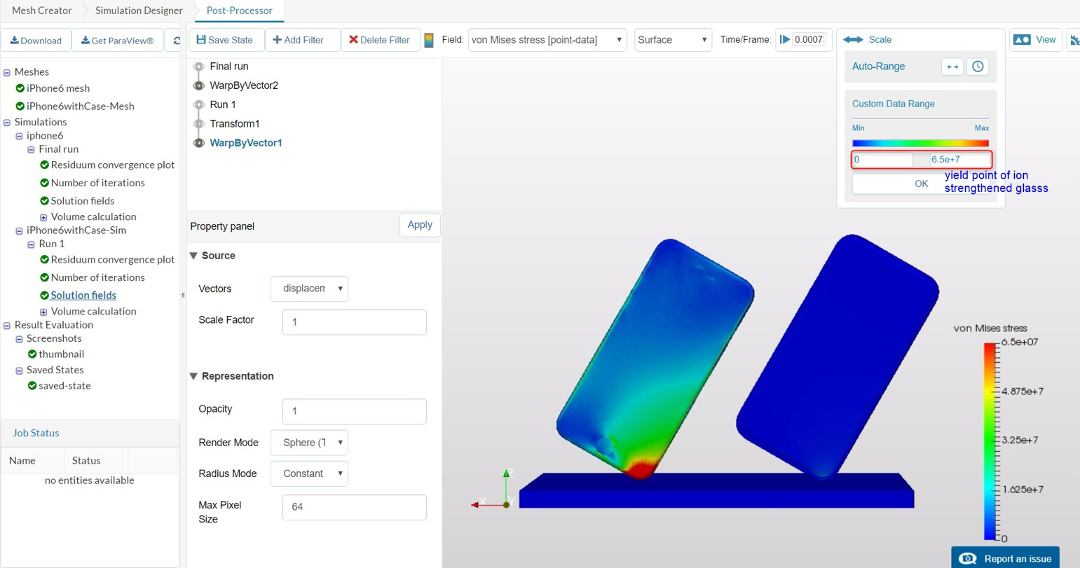
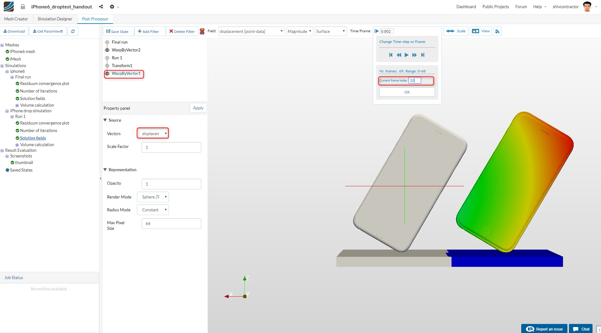
Warp by Vector:
This filter enables the user to dynamically visualize the displacement of each element. To add the filter to the iPhone with case, click on Transform and Add Filter. Select the Warp By Vector Filter.

After the result loads in the viewer, a distorted image may appear. Set the vectors to Displacement to resolve this. Also, change the Current Frame Index to 20 from the tool bar on the top of the viewer.
To add the filter to the iPhone, click on Final Run and Add Filter.
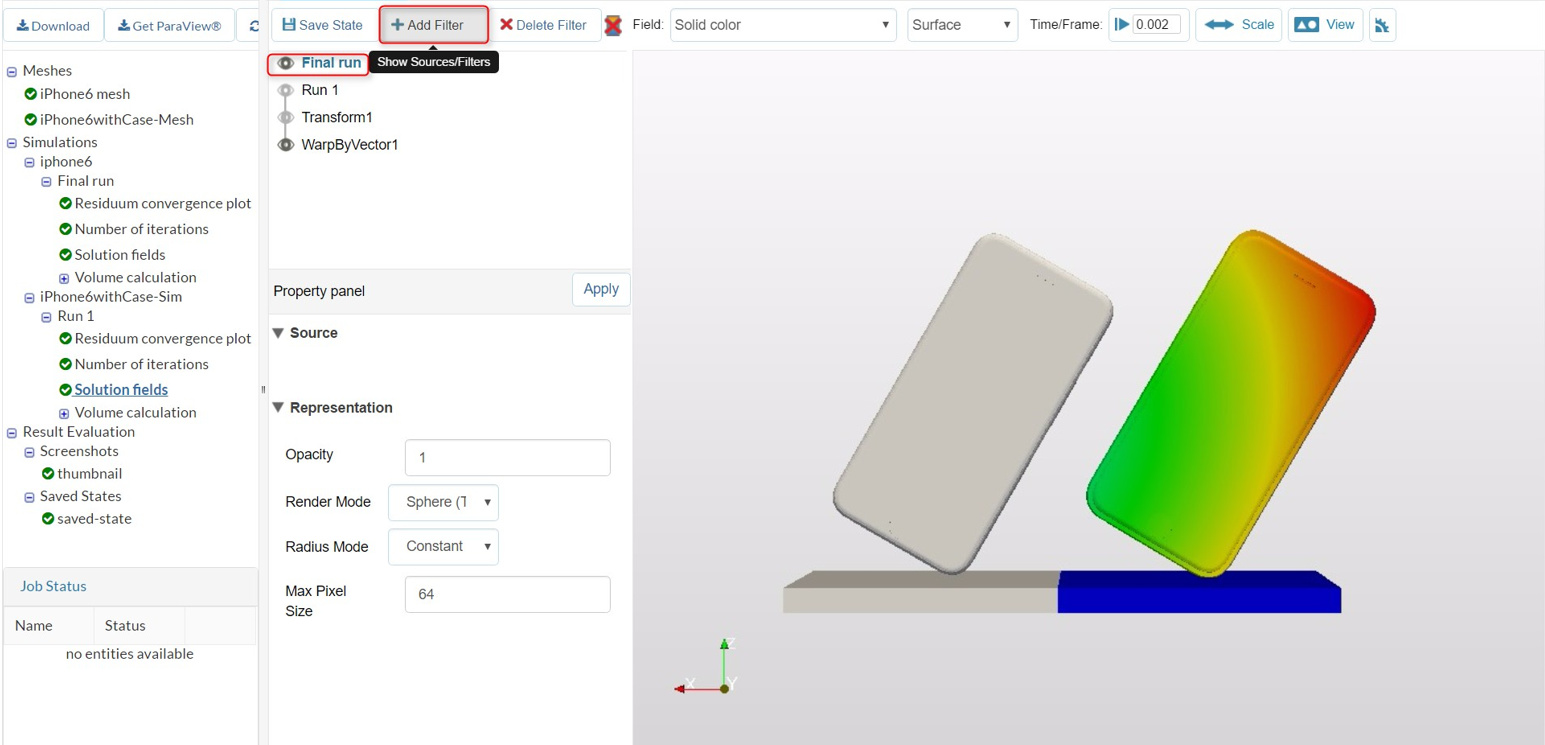
Select the filter, warp by vector.
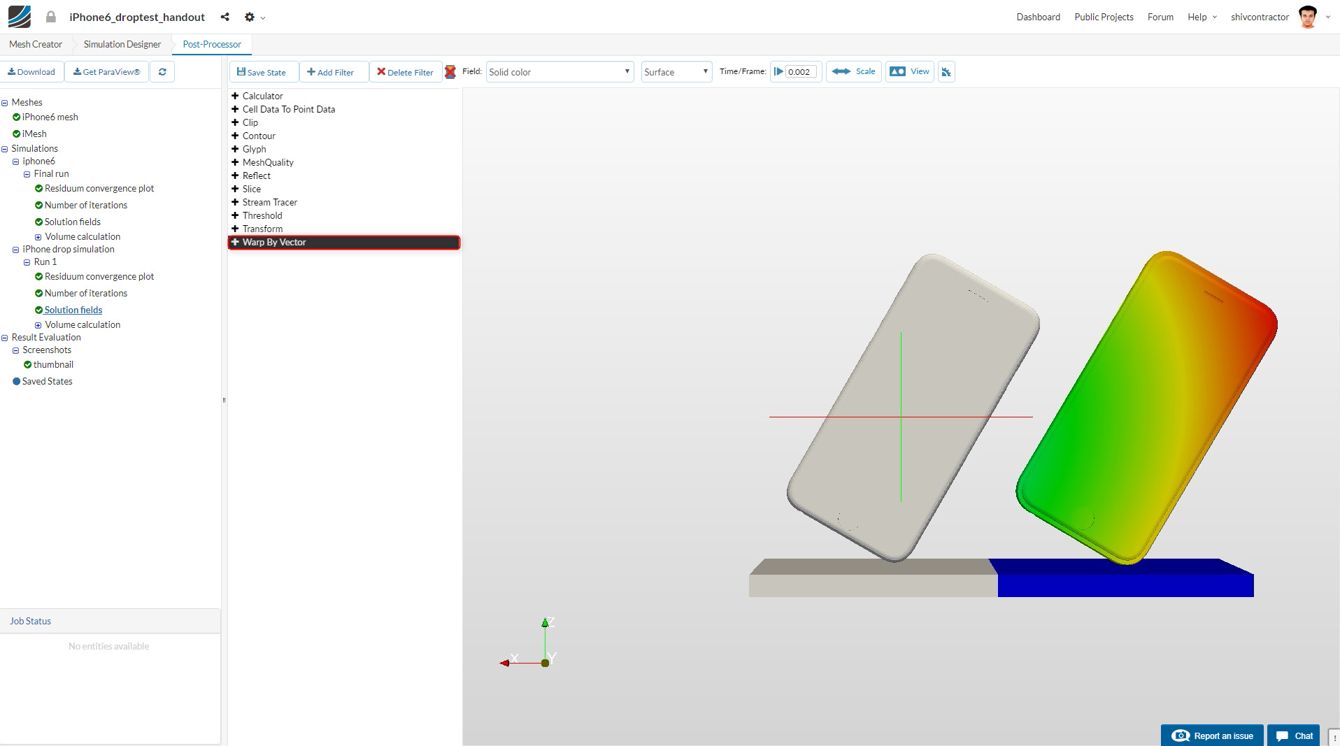
Select the Warp by Vector Filter again.
As shown previously, set the vectors to Displacement and change the Current Frame Index to 20.
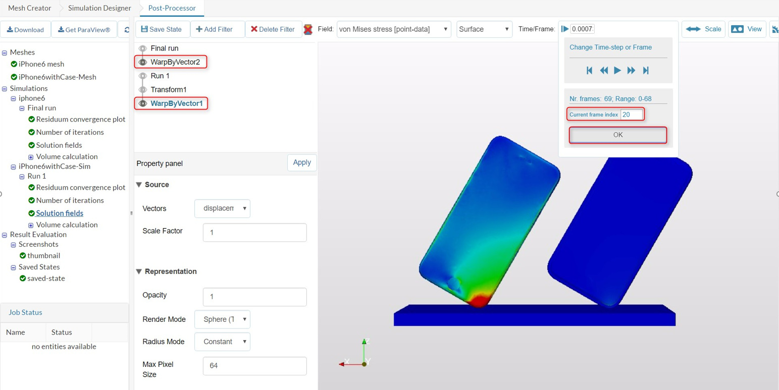
You may now visualize the stresses by limiting the range to 65 MPa which is the yield strength (or the breaking point) of the iPhone glass.