If I set up a simple vertical hollow tube (20mm OD, 16mm ID, 400mm long, aluminium) with a fixed constraint on the lower end face and a compressive load on the other which exceeds the critical Euler load (>>80kN) the simulation doesn’t obviously demonstrate Euler buckling. The only way to tell there is a problem is that, once the load exceeds the Euler critical load, the displacement becomes static. Is there a better way to visualise this?
Good evening @irving,
this is already on the roadmap of SimScale as mentioned by @ahmedhussain18 in this post.
@afischer or @dheiny might give you an insight into that upcoming feature.
Cheers,
Jousef
Thanks for that information & link. I note you consider this a 2d problem but that’s just an artifact of the way that @alabrazi presented his problem. Mine is ultimately a 3D problem as the columns are legs to a structure.
There is a more general point here - the representation of failure modes in SimScale. If I set up a simple bending of beam example and I increase the load the only indication I have of failure of the beam is when the displacement becomes non-linear. Or am I missing something?
@Jousef
Thanks, that’s a very useful approach.
It would be nice, in the future maybe, to see failure graphically represented in the WarpByVector filter (or, better, a dedicated ‘Failure’ filter) based on the material properties and a ‘safety factor’ value.
rgds,
Irving
I’m also interested in same, can you also notify me if this feature is on track?

Hi @gkotelnytskyy,
please don’t forget to vote for this feature here: Buckling analysis feature addition request
Best,
Richard
Is there some workaround before the feature is added.
I.e. applying small lateral force to the column – would it work to the same effect?
Hi @gkotelnytskyy,
as long as you know in which range the critical load will be. this might work.
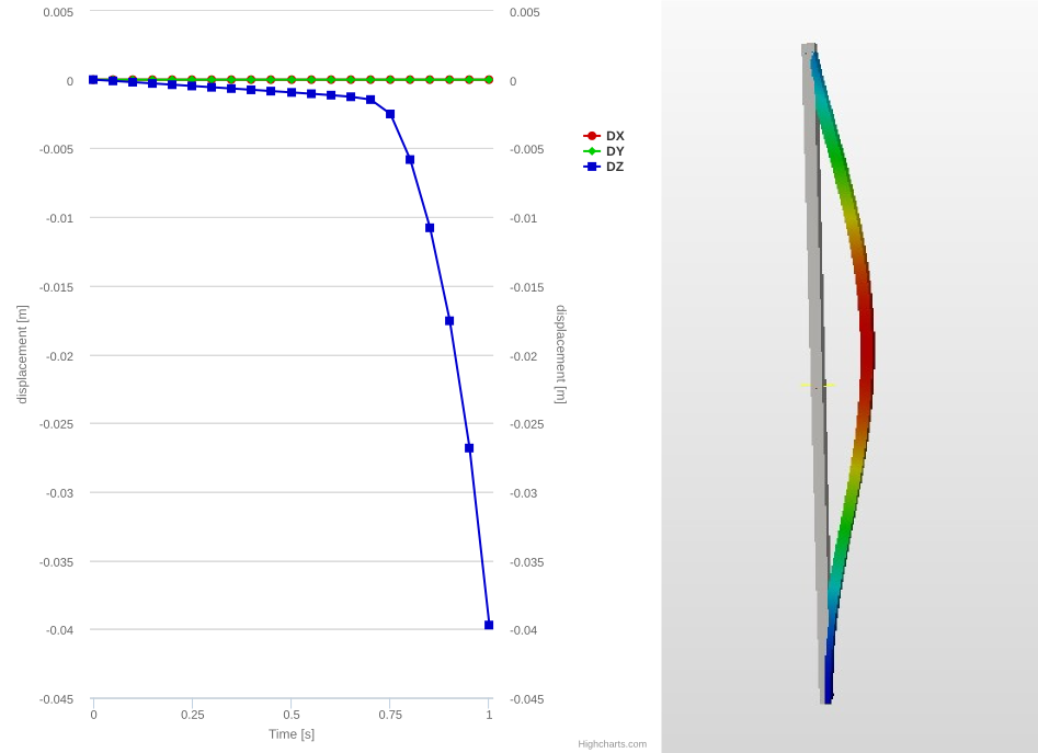
I made a small example, with a fixed end + pinned collumn under compressive load: Buckling Test by rszoeke | SimScale
From hand calculations the critical load should be about 30.31KN.
The nonlinear analysis shows a buckling behavior between load step 0.7 and 0.75, at an total applied of 40KN, whis is betwen 28KN and 30KN:
Best,
Richard
Thanks a lot, @rszoeke, this is the most helpful.
Why did you use non-linear simulation in your project? Isn’t buckling linear at first?
Hi @gkotelnytskyy,
this is exactly what this is about. As we don’t have “Euler buckling” available we need to go with a nonlinear analysis to be able to represent the change in geometric stiffness due to applied loadings and small geometric perturbations.
If we would have used a linear analysis, the above graph would stay linear for any given load.
Best,
Richard