Error Particles traces - Boundaries picking

Hello,

First of all, thank you for the great job with Simscale. I would not ever imagine I would get to a result in such little time as a beginner. It is really amazing so thank you. I hope prices are great :).
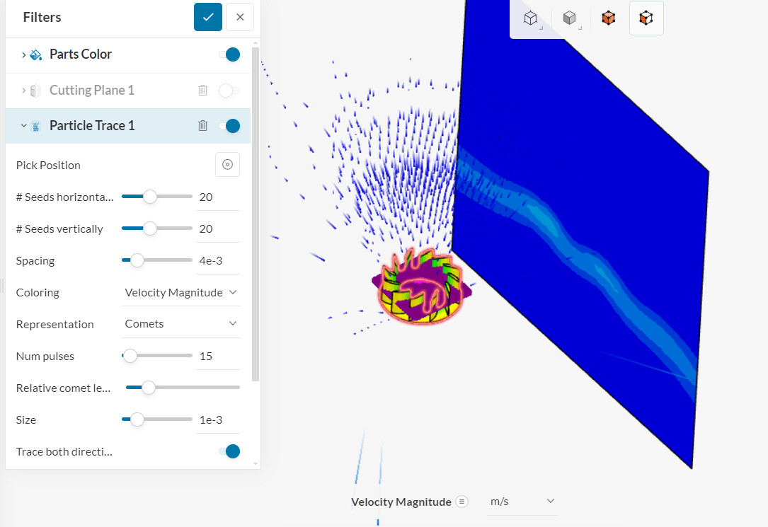
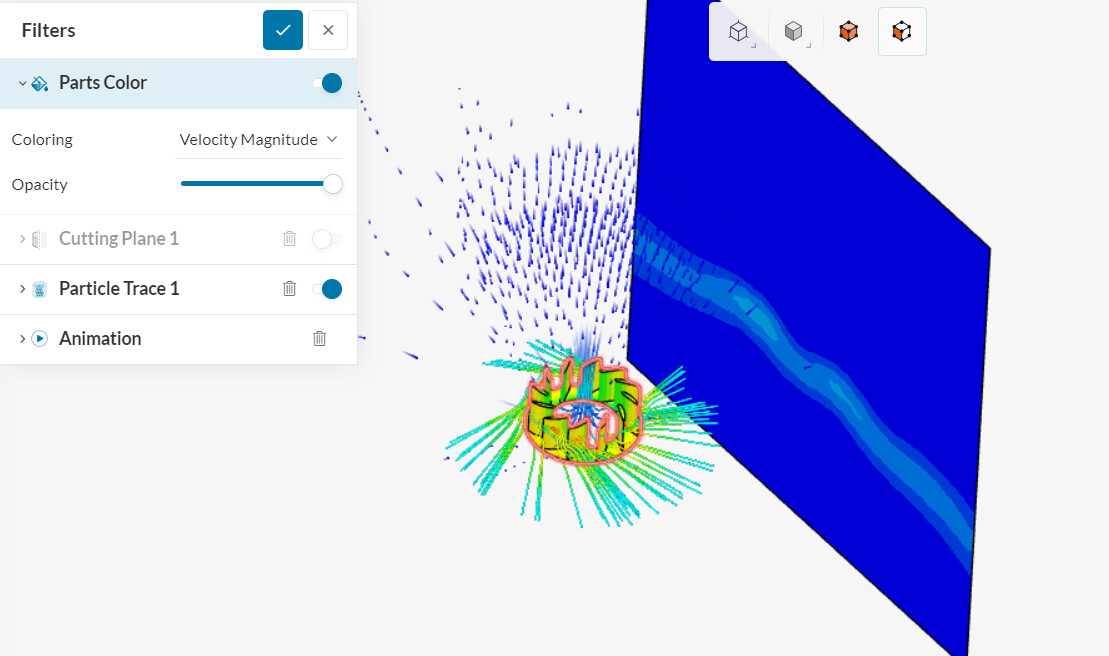
I encounter issue with the particles traces in my design.
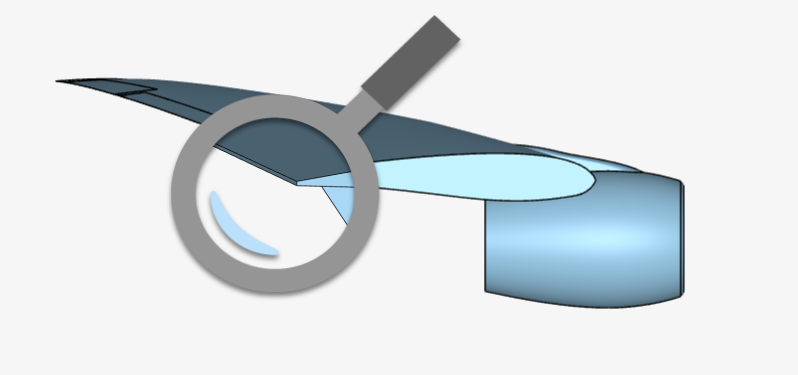
The goal is to simulate the rotation of a fan in an indoor low turbulence environment and to observe the move of air around and in it.

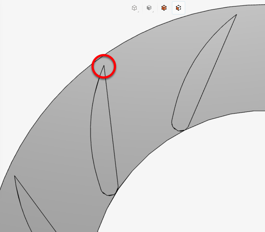
One the first simulation where I got some results I realise that the particles trace cylinders simply disappear in the fan blades.

After looking around I presume that the boundaries are the issue : Wall no slip (fan) + custom pressure inlet outlet ( flow) so I do another simulation with 3 boundaries assigning faces to pressure Inlet And Pressure outlet + Wall for the fan
Same issue arise. I also observe an loss of velocity of the fan.

As I didn’t understand the cause of the issue I try despite the initial advise to remove the rotational cylinder to set instead the fan’ boundary as a rotational wall .I try once the boundaries for the flow box as Pressure Inlet And Pressure Outlet and once as custom pressure inlet and outlet, And in theses configuration with the rotational wall, miracle it seem to work.
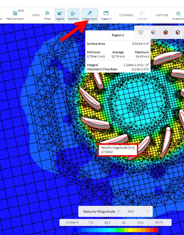
But - I observe each time an even bigger loss of velocity. The velocity magnitude dropped at the end considerably by a factor of 3 more. So I am really wondering if I did things right. I have to change the legend drastically to make appear some colors… I got from 36m/s to 2m/s

Can you kindly review the simulation and confirm that it is correct this way?
The boundaries are a tricky part because there is no special entrance of air. It is just a fan turning into air, not forced, normal conditions. So despite the particles traces seems to works into the last simulations, the fan on the other side doesn’t seem to work anymore. Thank you for your help.

Hi @Kouz, sorry for the delay and thanks for posting at our forum!

Looking at your simulation, it seems like you have a problem with the convergence of your model (even if the final results were given, there were bad values for the residuals).

To solve that issue, you can apply the workflow provided by this tutorial. That problem seems to be caused by the low quality of the generated mesh, which in turn happened because of some unwanted features of the CAD model. In order to inspect your mesh quality, take a look at this tutorial.

If you take a look at the Volume Ratio, for example, you can see that it’s way outside the desirable range:

Under the “Mesh quality” option, we can take a look where the bad cells are, and we find out they are near the tips of the model:

If we inspect the mesh using a cutting plane in the post-processor, we see that the distorted elements start to form near the tips of the blades:

That probably is due to the fact that the edges are very sharp

Following the steps provided in the first tutorial, you will notice an interesting aspect which is that the trailling edge of the airfoil is cut:

so that the mesh for the boundary layer is more comfortably generated. In your case, the blades’ edges are sharp, which makes the generation of mesh around it difficult.

As a final remark regarding the velocity you mentioned, it’s always important to keep in mind the results you’re expecting. In your case, the velocity at the tip of the blade is expected to be something like

\mathrm{v_{tip}} = \omega \mathrm{R}

Since your \omega = 600 \; \mathrm{rad/s} and the radius is \mathrm{R} \approx 5 \mathrm{cm}, the expected velocity at the tip should be \mathrm{v_{tip}} \approx 30 \; \mathrm{m/s}, which is near the value we encounter when looking the velocity with a probe point:

1 Like

Hi,

On the particle trace side of things: when particle traces hit a solid wall (i.e. a no-slip wall), they will ‘disappear’ from the viewer, but they are still accounted for from a mathematical perspective in the simulation.

As a tip: you can use a cutting plane as a seed face for your traces. This might give you a better visualization.

On a side note: I would have expected this equipment to be simulated with a rotating zone, not with a rotating wall. So your first link looks better than the other ones.

Cheers

1 Like

Thank you Igor, Ricardo,
Can the mesh improvement will improve the rendering of the visualisation? Or in the shown example it doesn’t really matter as long as the simulation could go through?
This is interesting Ricardo, indeed presenting the turbine correctly so that behaviour is correctly understood by a buyer is important. I regret that slip walls are presenting less good rendering than others despite their mathematical value. Is there any other wall or boundary , that would give correct particles traces without disappearance from the viewer? Even without considering mathematical values for only correct visualisation? ( cutting wall are a good tip but despite having tried quite a few times, can’t get a satisfying result )
When you say" looks better", does it means "should be correct ? :stuck_out_tongue:
Thank you and looking forward to reading from you.

By “the first link looks better than the others” I mean that the setup is more adequate and the results look physical to me (I’m not referring to accuracy, as I haven’t run any tests - i.e. see this article).

Using slip walls on the turbine doesn’t make sense to me, since the blades are physical walls, meaning that relative velocity = 0 on them. With that being said, traces will still disappear when they touch a wall (this is expected). I’d suggest playing with the trace filter settings to improve visualization, as well as looking at quantitative data (torque/power, etc.).