hello sir
i am finishing my research and raising the title of uav wing comparison. I’m still confused with the drag coefficient. please help me thanks sir.
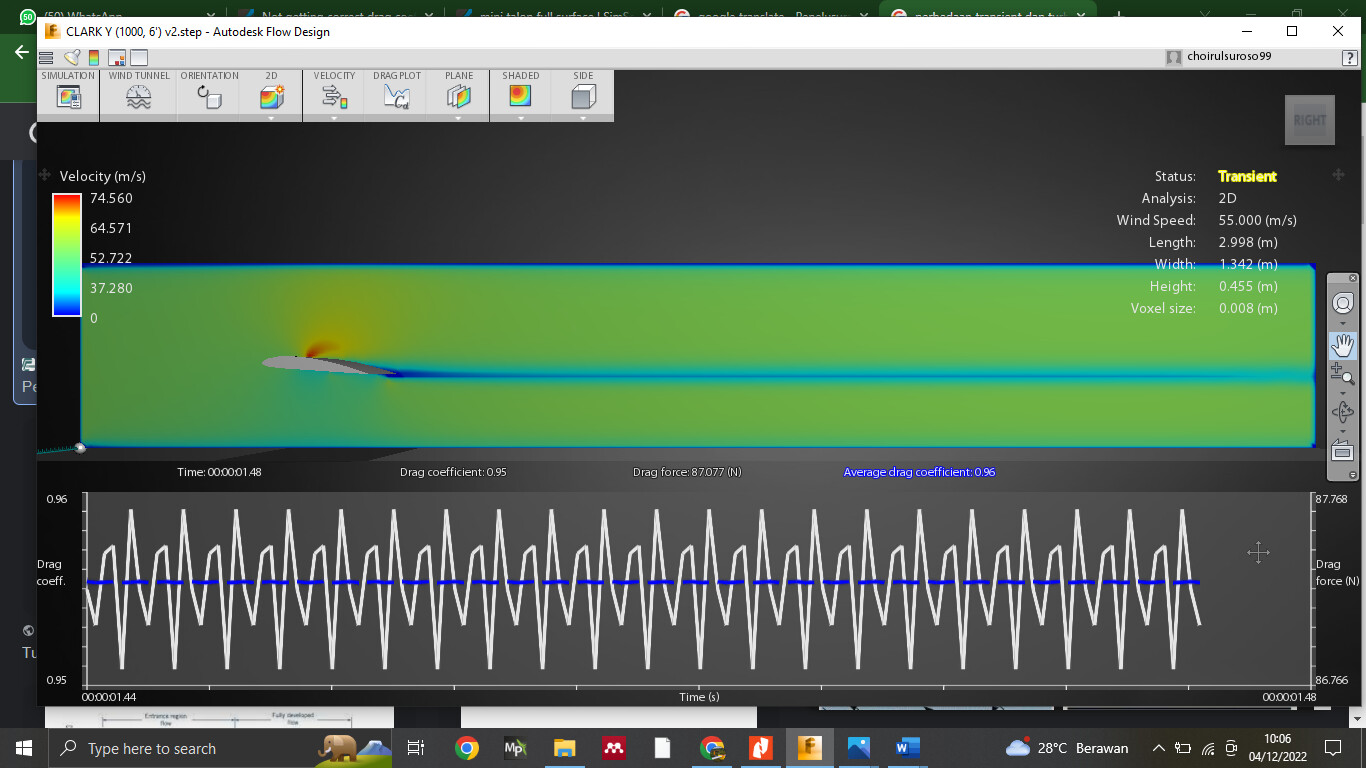
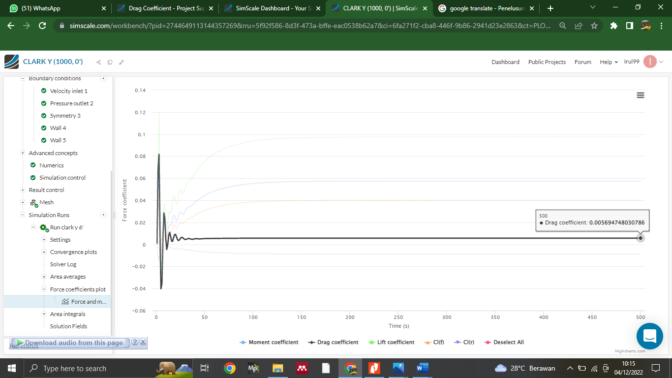
where I get the correct coefficient value, I simulate with simscale to get a drag coefficient of 0.00569, while trying on Autodesk Fluid Design to get a drag coefficient value of 0.95
Hey @Irul99 , thanks for posting this. Having a quick look into your project I’ve noticed that the reference values (area, length, moment point of interest etc.) are not conveniently set in result control. Could you please make sure that you’re using correct reference values to non-dimensionalize flow coefficients in both softwares?
Another thing I’ve also noticed is that you’re using a 2D simulation type in Autodesk. With the current setup in SimScale, you’re also counting for the 3D effects as well. (vortices forming near the tip of the wings, increasing the drag due to lift) In order to avoid that, please cover both sides of the wing with either a symmetry plane or a slip-wall boundary.
hallo sir.
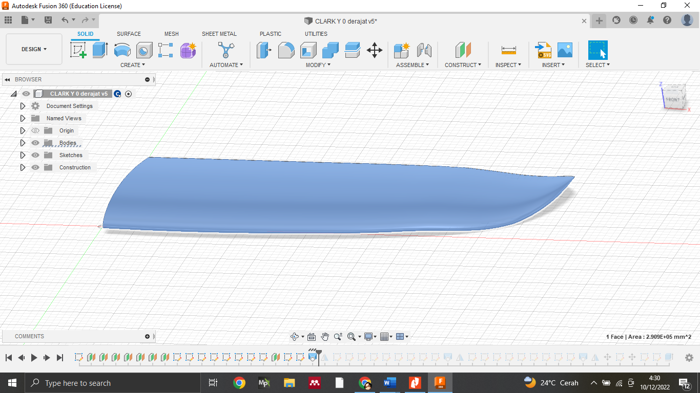
I just finished my final project simulation, here I’ve tried to read the references I got regarding the lift coefficient and drag coefficient, I want to ask your opinion, sir, is the process I’m working on correct? I want to know the lift and drag to compare with other wings, for the wing area I measure the front impact surface only the air intake and the airfoil chord.
I really hope for an explanation from you if there are suggestions I am very happy
regards, choirul
Hello @choirul , common approach is to use the wing area that is seen from top. For rectangular wings it’s going to be (chord)x(span) however, for this kind of sweeped wings it’s good to take use of your CAD software and calculate the reference area accordingly.
One other thing that I’ve noticed in your result control:
-Moment center is picked as (0,0,0) which correspnds to the leading edge of the wing. Usual approach to calculate the moment around wings is to pick a point located at the quarter of the root chord. (0, 0.25xchord, 0)
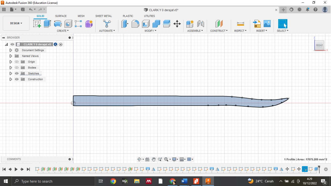
I have followed the article that SBlock shared and I understand it is the front view of the wing. I apologize if the reading is wrong, here I include a picture. please choose the correct image, sir. thanks
hallo sir.
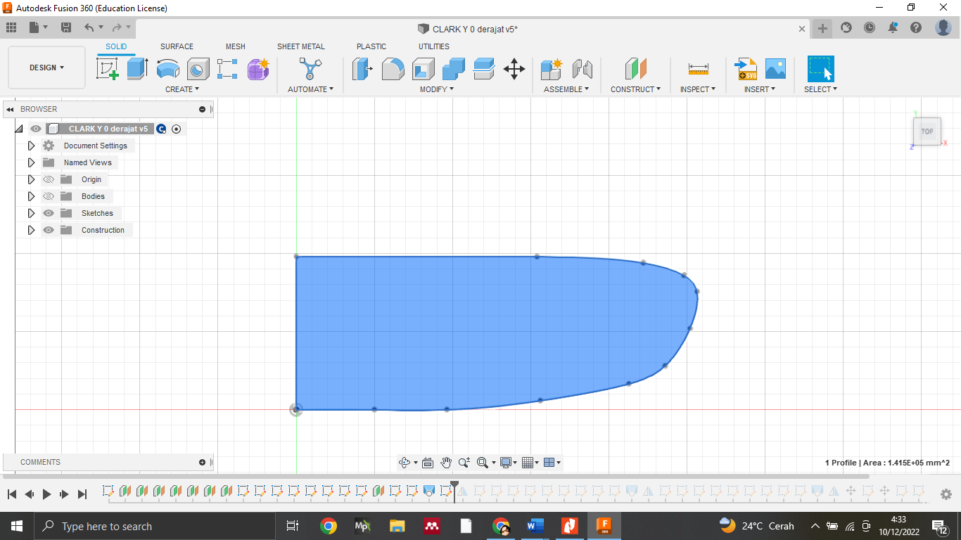
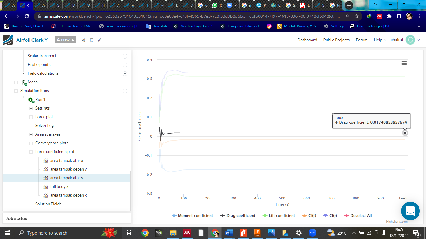
this is the work I’ve done, I’m still confused about which value is correct in determining the lift and drag on this airfoil. I entered 3 different values for the area, there is an area that looks at the top of the wing, an area that looks at the front of the wing, and an area that looks at the full body of the wing. from the references that I have read many different areas, some say from the front view and also from the top view. I really need your help sir. thanks
best regards.
choirul
I’d like to make a few things clear before we proceed with the reference area definition. First of all, we need to understand the need of non-dimensionalization of forces in aerodynamic simulations. Non-dimensionalization allows you to compare resultant forces properly regardless of the scale of application and to reduce the need of large number of simulations. In theory, designer is free to follow any convention (e.g. using side/top/front view) while defining the necessary parameters (e.g. reference area, reference length) as long as they stick with the same convention during the whole design process. However, there are already a set of conventions that are determined in each industrial application that we are recommended to follow.
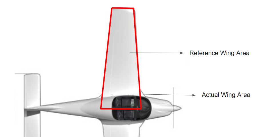
In aerospace applications, usual convention is to use the top view of the wing as the reference area. Using a simplified trapezoidal shape to represent the reference area for swept or rounded wings is an acceptable approach in early design stages. In the figure below, you’ll see how the reference wing area of a Tecnam p2002 can be calculated:
Please be aware that here, the reference wing is imaginary and extends to the fuselage of the aircraft. If you’re not working with a full aircraft configuration, you can follow the same procedure with only top view of the wing.
there are some that i read, but i can’t find where they got them. because I also calculated with the formula but the results are very much different.
my research compares lift and drag to determine which airfoil I will use later.
Just to be on the same page, are you interested only in the 2D affects of the airfoil or would you rather investigate the whole wing? At the moment, you’re not only seeing the performance of the 2D section of the airfoil, but also the affects of whole wing parameters. (sweep, taper, winglet structure, aspect ratio of the wing etc.) Unless the article or documents are presenting simulation results of the 3D wing geometry as well, this might be the cause of the difference.
If you could provide any links to your references, I’d be happy to help with your approach.
I see, could you refer to my previous post and share the reference if possible? If not possible, please make sure that whole simulation experiment follow the same procedure as the one presented in the reference. (Including the geometry) Best!
thank you sir, for now I just want to compare the amount of drag and lift based on AOA to choose which wing I will use for my uav plane later.
best regards
choirul
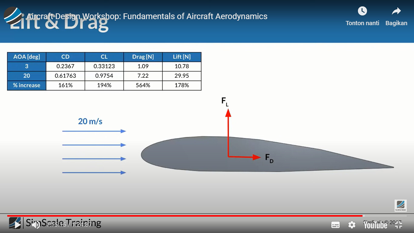
This is rather an old project. However, I believe the forces are calculated in SimScale platform as mentioned in previous minutes, and then non-dimensionalized accordingly. It’s almost as the same as your methodology at the moment.
A few notes here to avoid confussion: Please be aware two simulations are performed in this workshop with different angle of attacts. This means that direction of lift and drag coefficients should be adjusted according to the angle of attack value. Drag force should be represented in parallel to flow direction, and lift force should be perpendicular to flow direction.