I have run the simulation of cfd analysis but the convergence plot is not converging and want to know whether if i am going wrong somewhere.
I am particularly referring to the simulation " Stationary Fine "
but similiar convergence trend is obtained for all the cases…can anyone help me out please ?
The simulation you are referring to has converged. Some remarks from my side:
Why do you choose the bottom wall to be no-slip?
You can use two custom boundary conditions with one defining the BC of the propeller and the other one the bounding boxes. An example can be found here: Propeller AMI.
The velocity you put in is not going through the propeller as it should
It should be the negative x-direction and you have defined the geometry to be stationary so far. I do not think that using a moving wall velocity of the bounding box is a good substitute for the AMI/MRF approach. So you should consider working with that. That’s why you have probably opened up another post.
Is it converged ? But the tolerance is given as 0.000001 and shouldnt all the convergence lines go below that for convergence to reach ? I saw it in some of the sample projects so thatswhy asking.
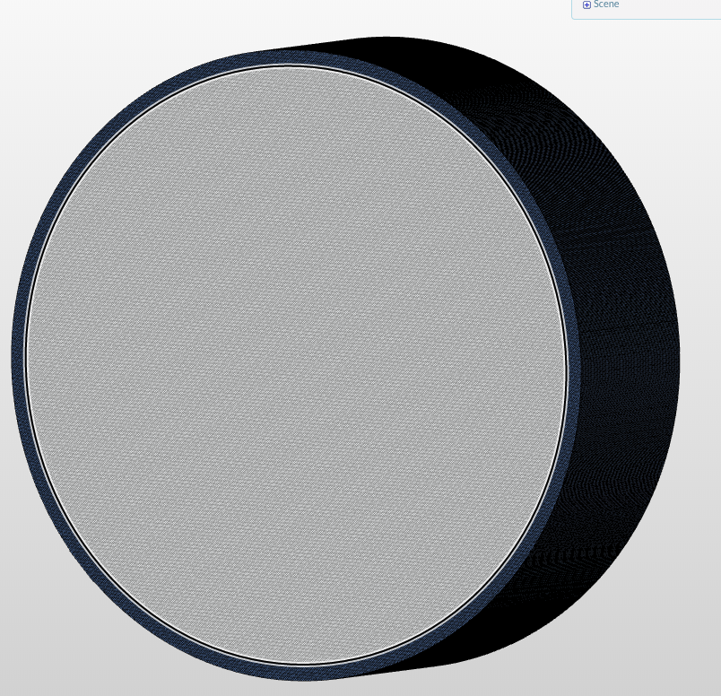
Actually @jousefm its not a propeller its basically a kind of tyre with spokes and in order to create road conditions i am giving no slip wall to the bottom layer and tyre. Also to mention those conditions are mentioned in the reference paper i m validating
And yes for the condition where the tyre is rotating with respect to ground i have planned to put
Moving wall Velocity - Bottom Layer
Rotating wall velocity - Outer surface of tyre
Rotating Zone cell condition - To the spokes and hub
the rest of the conditions as it is.
Do you feel it will be the correct approach or if you can suggest something else i will be really greatful to you
Really looked like a propeller though Now it makes sense! Do you mind sharing the paper here again? Would be great also that others can have a look at it and I want to see what the results there are saying.
For the boundary conditions (BCs) you could use:
Freestream BC: Custom BC with Inlet-Outlet for velocity, fixed value for pressure (0 Pa) and adapt k&omega values
Wall BC with slip on top and bottom (bottom can also be no-slip if you want to capture boundary layer effects - consider using slip when viscous effects are negligible or the mesh size is much bigger than the boundary layer)
For the wall you could indeed use the rotating wall velocity adapting the values for the rotation axis etc.
Sure @jousefm iw ill share the paper, dont have a soft copy of it yet.
As for results for the stationary case i am getting values of coefficients of drag and lift as 0.996 and 0.684. Whereas in the paper they are getting as 0.868 and 0.618. So i am getting a 14.6% and 10% error but the reasons for that could be because they have use RNG K Epsilon model and we are using Transition KW SST and they’ve conducted on ansys fluent whereas i am using simscale. So that in future to all my juniors i can suggest using simscale. That’s one of the reason that i keep asking so many doubts because i want my doubts t be crystal clear so that i can clear doubts of others. In a way i am trying to promote simscale you can say
Now coming back to the boundary conditions you mentioned. I tried for the rotating case of the tyre applying the same conditions as you suggest but the error is coming alot approx 35 % and also as i mentioned i saw in one of the Formula SAE workshop session that to capture the flow around the rotating spokes/rims they create a MRF region just around the spok. So when i am trying to do that and give meshing ( This brings me back to the other POST ) Mesh error is coming. All the conditions i have kept same but still its coming. Soo please can you help me out with it. Another constraint is that i cannot change the base mesh box size rest all stuff can be altered, well at the end i want my result. so please can you help me out with the meshing.
Sharing link of mesh error - https://www.simscale.com/workbench/?pid=430864919459540414#tab_0-0
Also can you please answer this :-
Is it converged ? But the tolerance is given as 0.000001 and shouldnt all the convergence lines go below that for convergence to reach ? I saw it in some of the sample projects so thatswhy asking.
If you have experimental data, do compare it against that rather than say another simulation. You never know how far off their values are. With that being said, literature I’ve read through generally agree that K-omega SST and RNG K-esp are quite good in predicting your needed values. For the K-omega SST model in particular, a full resolution solution with a y+ of less than 1 would ensure you obtain highly accurate results. Of course, you will need additional computational power in order to mesh and simulate a grid that fine.
With regards to your Formula SAE simulation, I’m not experienced in it so other will be more equipped to give you tips on this!
Convergence criteria is subjective and relates back to literature concerning what is deemed as converged. This can vary but in general a residual of 1E-4 is deemed as loosely converged, 1E-5 as well converged and 1E-6 as ideal convergence. So based on previous studies that you’ve mentioned if the residuals do not go below 1E-5 as you’ve mentioned then it is not converged. Why is it not converged can be due to your numerics or mesh typically.
Thanks a lot for jumping in so quick Barry (@Get_Barried)!
@simscale7yahoo - I totally agree with Barry here and especially if you are working with forces you can use them as your convergence criterion. Convergence itself depends on the mesh quality as Barry already said and should be measured with physical quantities as just proposed. Sometimes converged solutions have a nice graph but the results are “numerical garbage” so better be skeptical in any case.
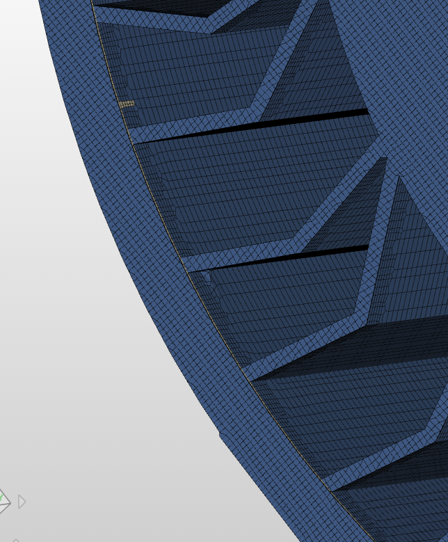
@jousefm perhaps if you or any other member of your team can help me with why i am getting meshing error when i am trying to create a MRF Region to capture the flow around rotating spokes. I will be really grateful
Sharing link of mesh error - https://www.simscale.com/workbench/?pid=430864919459540414#tab_0-0
I got the meshing but it really looks odd in my opinion and I do not think that it would make sense to give it a spin and waste core hours on a simulation. @1318980 & @Get_Barried, any comments on the mesh quality and if it is legit? I would have probably picked the side faces for the MRF zone and not put a cylinder right in the middle of the geometry but I might be mistaken here and your approach could also work.
Hey @jousefm thanks for spending time on it to mesh it. It seems like youve done in your profile the meshing, can i please have a look at the mesh settings which you gave ? Because no matter what changes i am doing to my settings it is not meshing and is displaying with an error message.
Also it will be really helpful if @Get_Barried or @1318980 can jump in to give their suggestions
Also i would like to add i was talking about this
Formula SAE where they have done for wheels, so if this can ring any bells and can be adopted to my project by someone i will be really grateful
Waiting for my colleagues to jump in here and give some suggestions The method I proposed was exactly what you posted - just mimicking the workshops exercise.
Hey @jousefm actually whenever i am clicking on the " CFD Mesh Tyre " nothing is happening
I don’t know why, can you post the complete link or something else so that i can have access to it.
Yes it will be really helpful if you can ask your colleagues to jump in and please help out
Talking about the method you proposed - So you mean to say that i should make changes to my cad geometry correct ? Can you be a little more specific with that please ? I didn’t quite get what you meant by " picked the side faces for the MRF zone and not put a cylinder right in the middle of the geometry"
Should work now I proposed to use the same approach as the in the Formula1 workshop where we pick one face and rotate it as you may have seen but let’s see what the others have to say
Hi @simscale7yahoo and @jousefm, I am not sure what is happening with the MRF. Looking at the latest project link from Jousef, it seems an MRF zone is created but with an additional shell? I think the MRF is too tight to the tyre, in the FSAE project the MRF was in the dish of the rim, allowing a solid to be able to mesh around the spokes. Here we have the MRF almost flush with the spokes. I think it would be worth extending the MRF symmetrically along the spinning axis, This will allow us to a single MRF.
Then as suggested a rotating wall can be applied to the outside of the wheel.
Hope this answers your question, and let me know if you still have trouble.
Hello Darren @1318980 first of all thankyou so much for showing interest in my project.
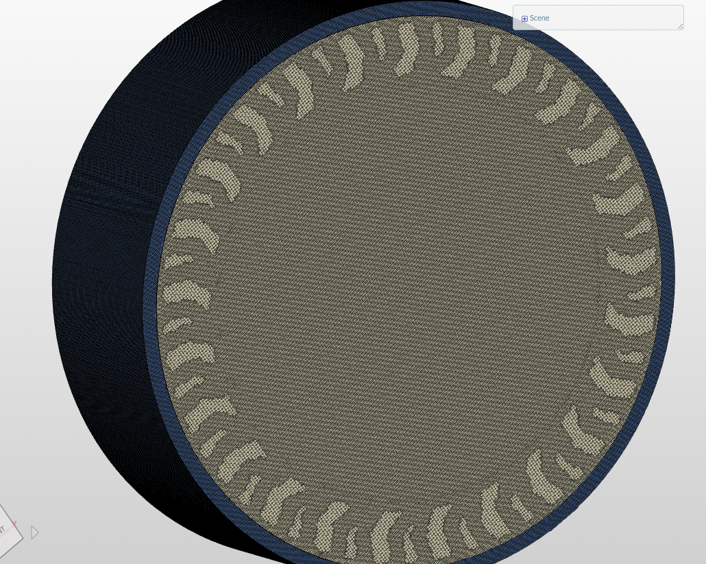
i think i somewhat got what you’re trying to say. In my case the spokes are intersecting with the outer tyre ( tread ) part. So my approach for modelling is that first i am creating normally my tyre and then i am creating a cylinder just the same diameter as the end of the spokes and assembling them both.
So firstly is my this approach correct ? I hope its not an issue if the MRF region is intersecting with the spokes or tyre.
Check out this link for the above geometry ( tweelrot_asm ) i am talking about and if its correct or not
Now coming back to what you suggested is that along the spinning axis if i extend my Cylinder region it might work correct ? I will model it and share over here if still meshing error occurs in that. Please keep checking this Forum Thread, i would really require your help throughout the process
Thankyou so much to complete Simscale team once again!