I am trying to simulate a shell and tube heat exchanger for a small cogeneration unit I am building from a 5kVA diesel genset. It’s just a personal project at the moment, and the heat exchanger is oversized on purpose. I just want to simulate it out of curiosity.
I have no previous experience with simulation software, so maybe I just made some stupid basic mistake.
I used this tutorial as a starting point and just changed some of the values: Conjugate Heat Transfer in U-Tube Heat Exchanger | SimScale
I had to increase the water flow rate a lot, because in the tutorial the 0.01kg/s comes out to just 36 L/h. The pump I am using is rated at 900 L/h and since I am obviously adding some resistance I put 400 L/h (0.11 kg/s) to be on the low side.
I left the flow rate of the gas as is for now, because I am not sure what the exhaust flow rate of the engine is and how to calculate it. I am sure its possible to get a rough estimate using the fuel consumption, cylinder displacement and RPMs, but I have to look into it some more. If someone here has a simple formula or can do the calculation quickly, I would be very thankful. The fuel consumption is 1.8 L at max load, displacement is 418cm³ and it’s running at 3000RPM.
Other than that I just changed some of the temperatures.
I am not sure if air is even the best material, because the exhaust gas is obviously not air. Is there a better alternative or is air close enough?
The error I am getting is:
Maximum number of iterations exceeded when calculating temperature from a thermodynamic potential. This may be caused by low-quality mesh producing unrealistic pressure in a few cells or inappropriate boundary conditions, fluid properties or time step. Inspect fields for large values in the last time step.
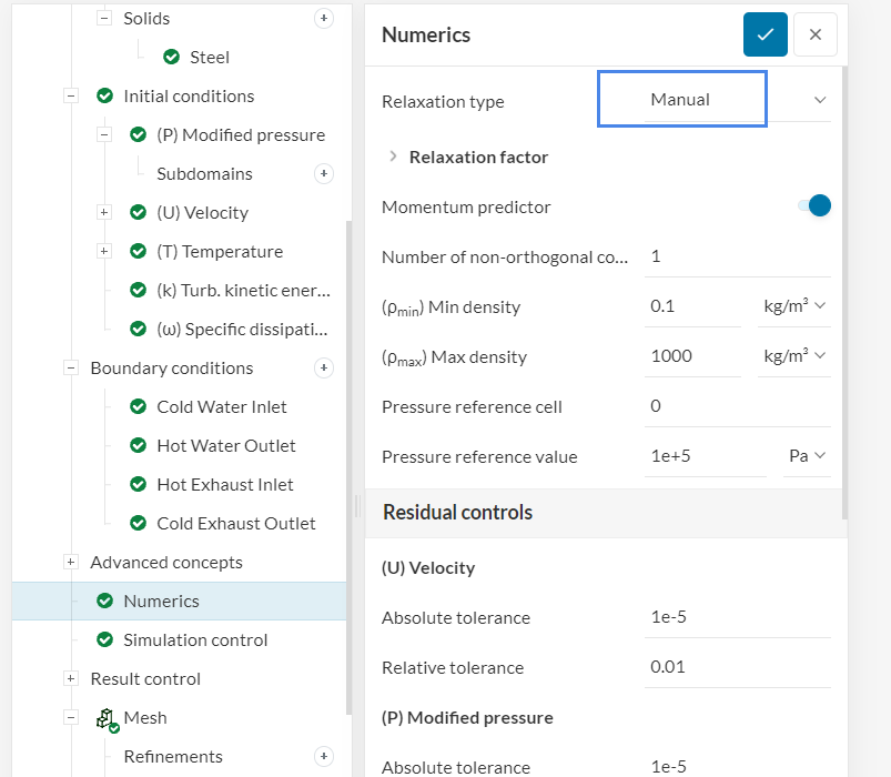
I already tried to increase the quality of the mesh and played around with some other settings, but I don’t really know what I’m doing.
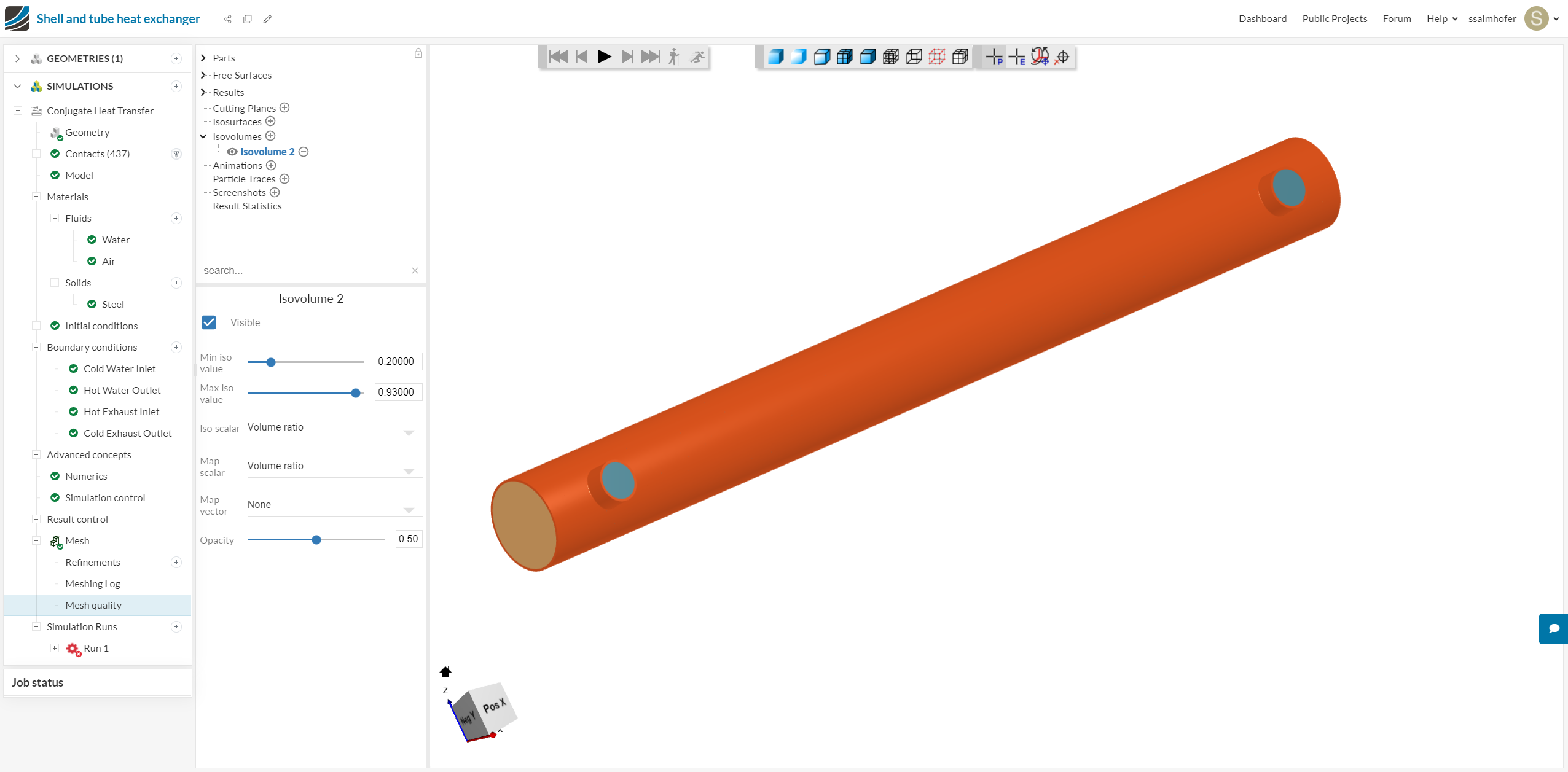
Hi there, it seems that the issue is mesh-related, I suggest you try to visualize the results as a start, to investigate whether there are bad cells. A way to do this is by using isovolumes, as described here: How to Check and Improve Mesh Quality | SimScale
Let me know about your findings, and make sure to add an Imprint operation too.
I checked the links and tried to use the isovolumes filter, but I can’t get it to work. I am not really sure what it is, but I tried to set it up like it says but I cant even set the min and max values correctly because it only goes to 1 for me. I thought it might be a percentage, so I set it to 0.20 and 0.93 instead but I still don’t see anything like on the site:
It did read a bit further about mesh quality though. What I found out is that it might be bad that my CAD file (Fusion 360) consists of multiple bodies, because the meshing could create some voids between the parts. So I combined them all into one body in Fusion and because I read sharp corners are bad as well, I threw in some small fillets on all internal edges. In reality I will braze it together, so there will be filets too, so might not be a bad idea anyway in case it makes a difference for the water flow.
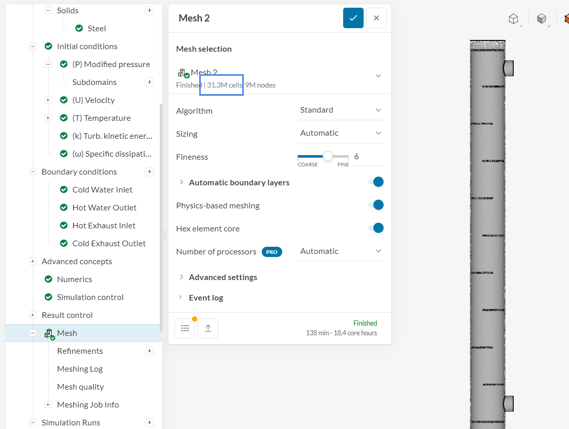
Then I re ran the mesh and tried the simulation, but still get the same error…
I’m sorry for the stupid questions, but I don’t know what I have to set there and what I’m actually looking for. This is my first ever simulation project. Could you please give me some more details on how I can find the issue?
PS: it would be a good idea to use a coarser mesh. The current mesh has more than 30 million elements and it probably won’t run all the way until the end, given the community plan runtime limitations.