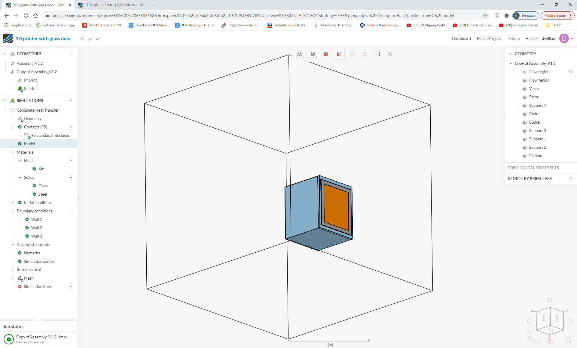
Hi there This is probably because some faces belong to more than one region (as they are in contact).
Maybe you can create your external flow volume in a way that it is not touching the edge of the 3D printer?
If anyone else has a suggestion, feel free to contribute
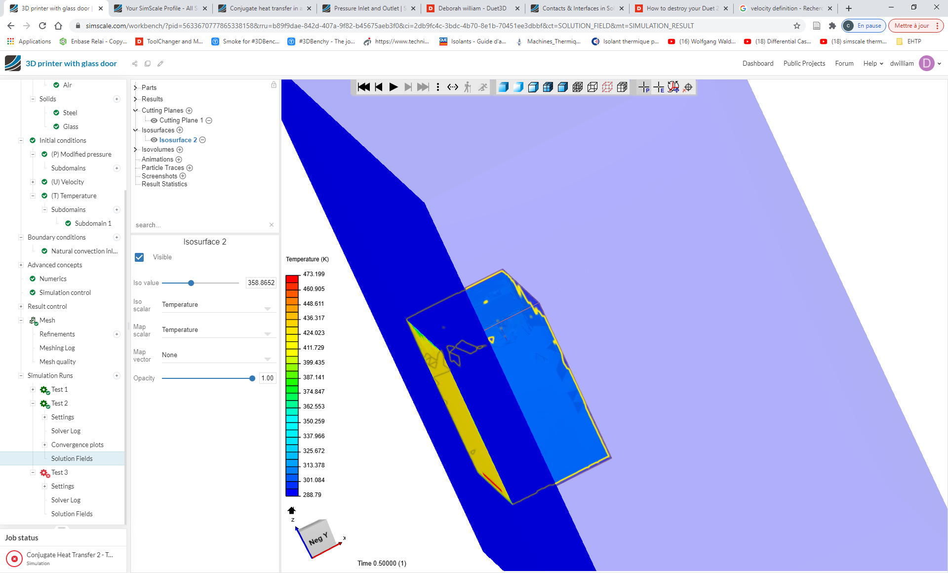
Thank you for your help, i was able to run the simulation but, i have another problem.
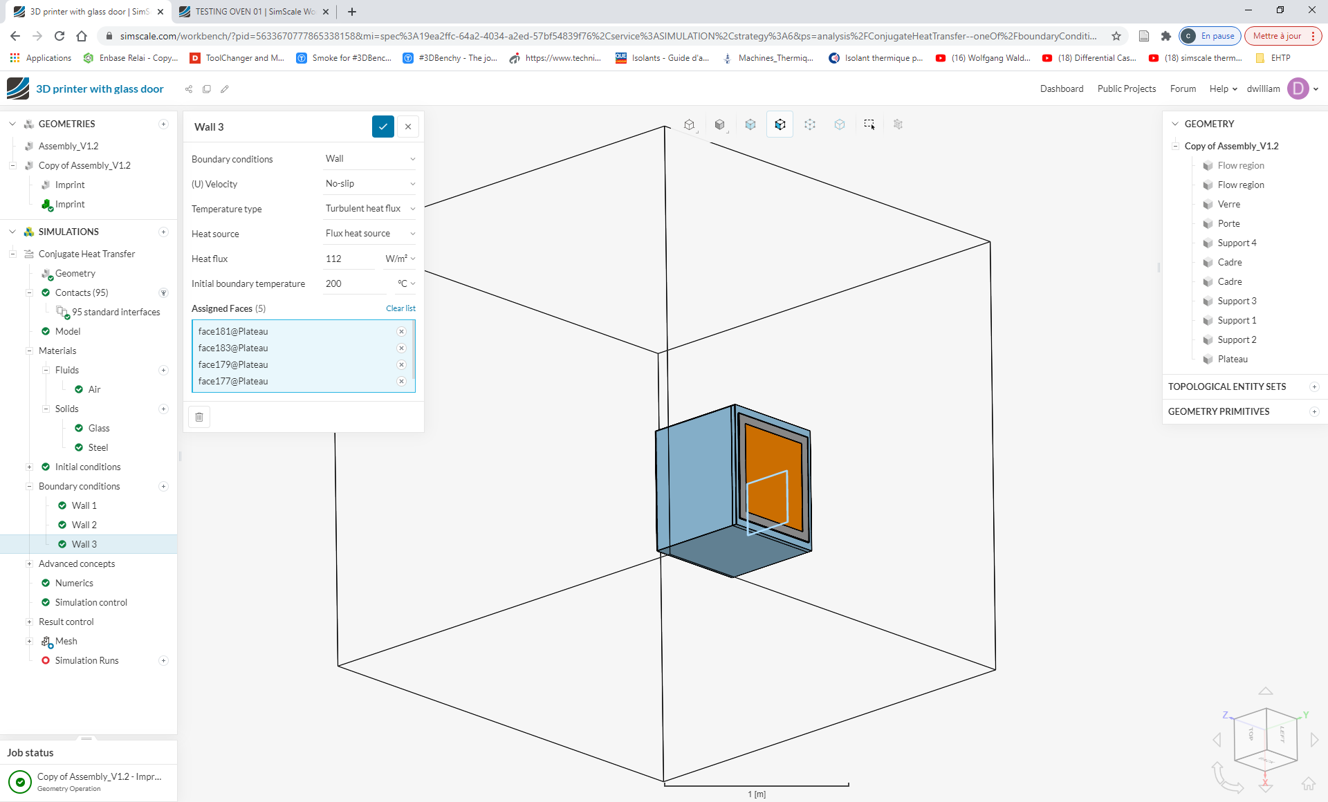
I think that i didn’t choose the right boundaries, you see i calculated that I should have a temperature of at least 149°C (422°K) at the edge of the steel’s faces, but when I look at the results it shows 85°C (358°K) for the hottest part.
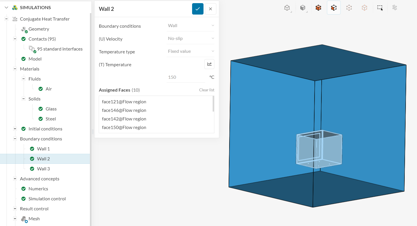
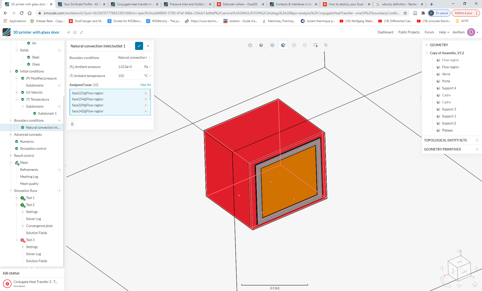
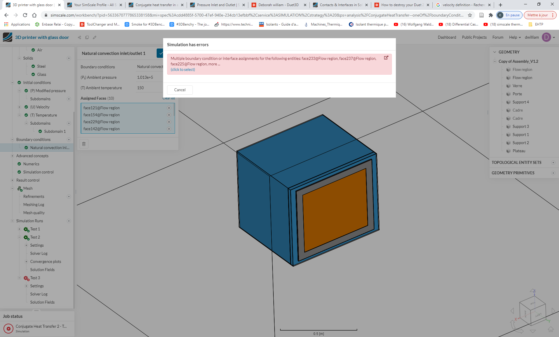
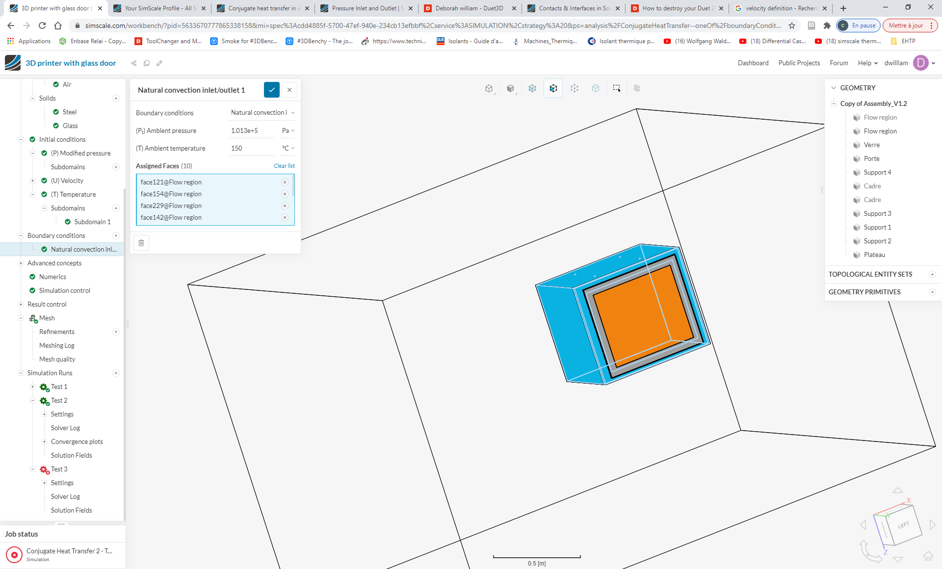
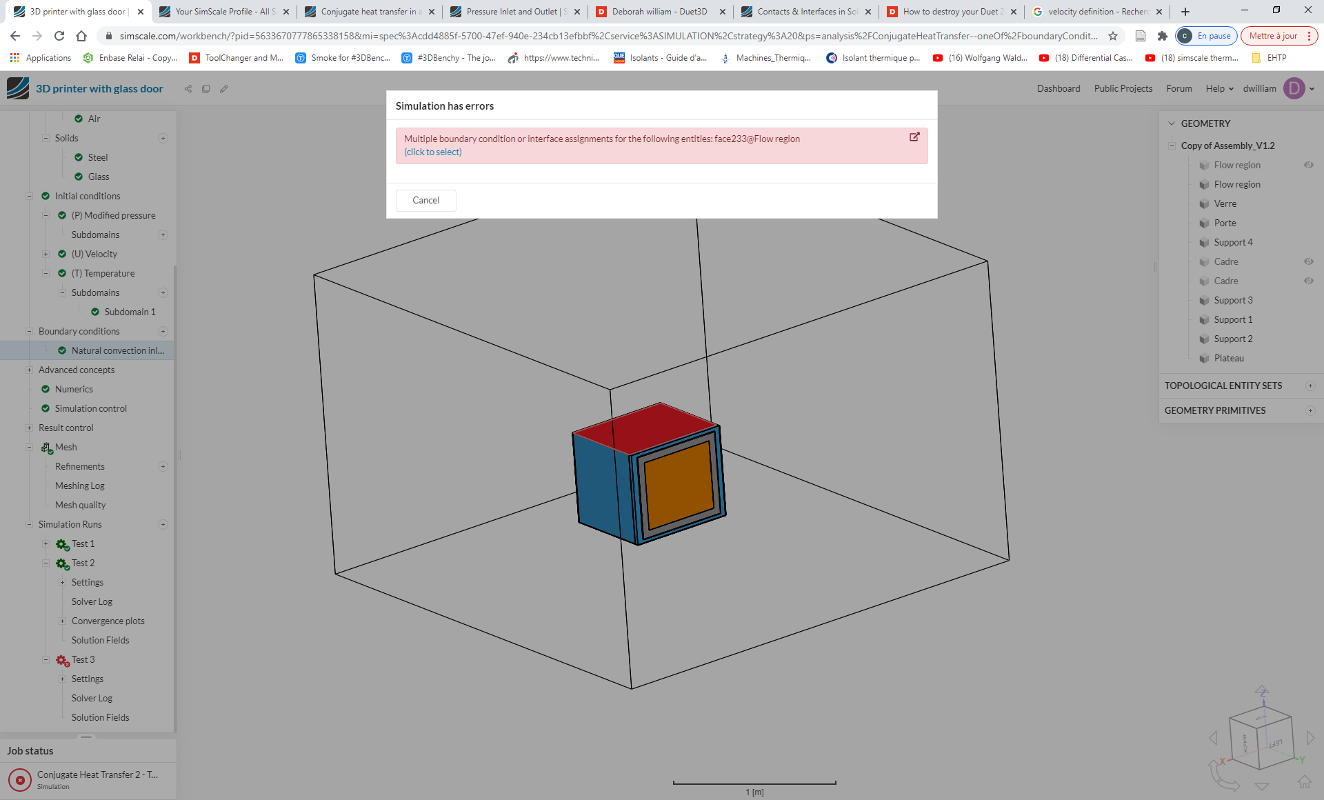
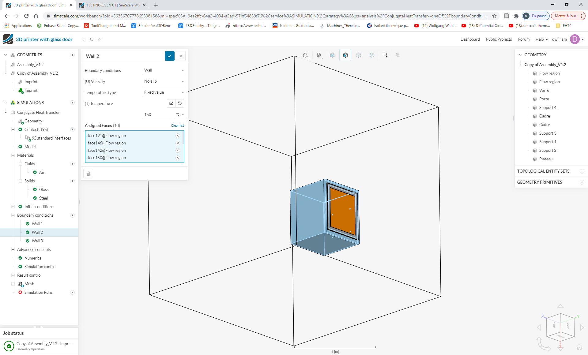
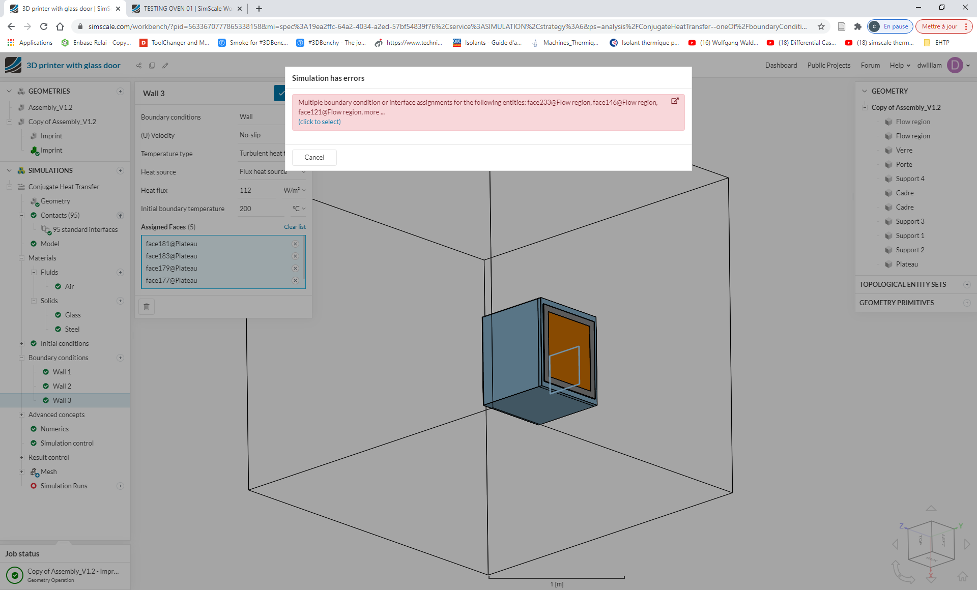
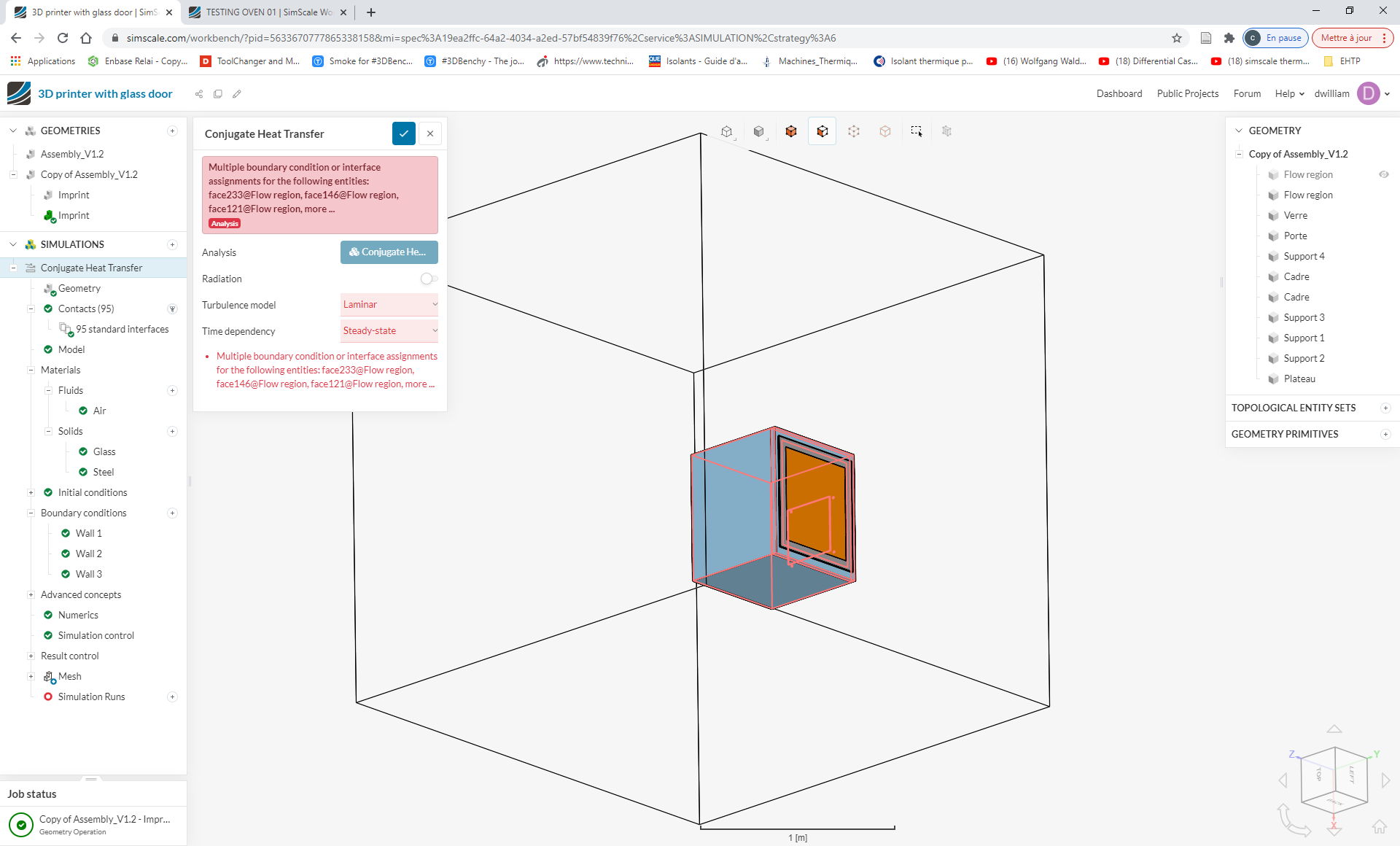
I try to turn of the boundaries of 20°C on the outside flow region that is surrounding the printer and adding a natural convection of 150°C to the flow region inside but when I try to launch the simulation I have this error.
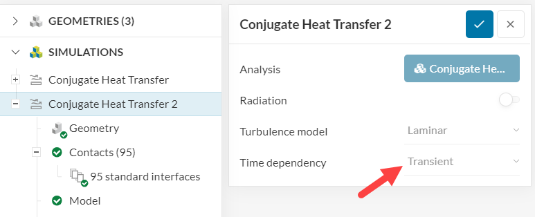
I noticed that you are currently running the case as a transient simulation. Is this a requirement for your analysis? Or would you be interested in the equilibrium state of the system?
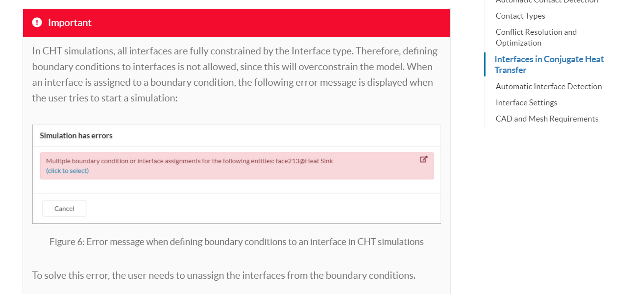
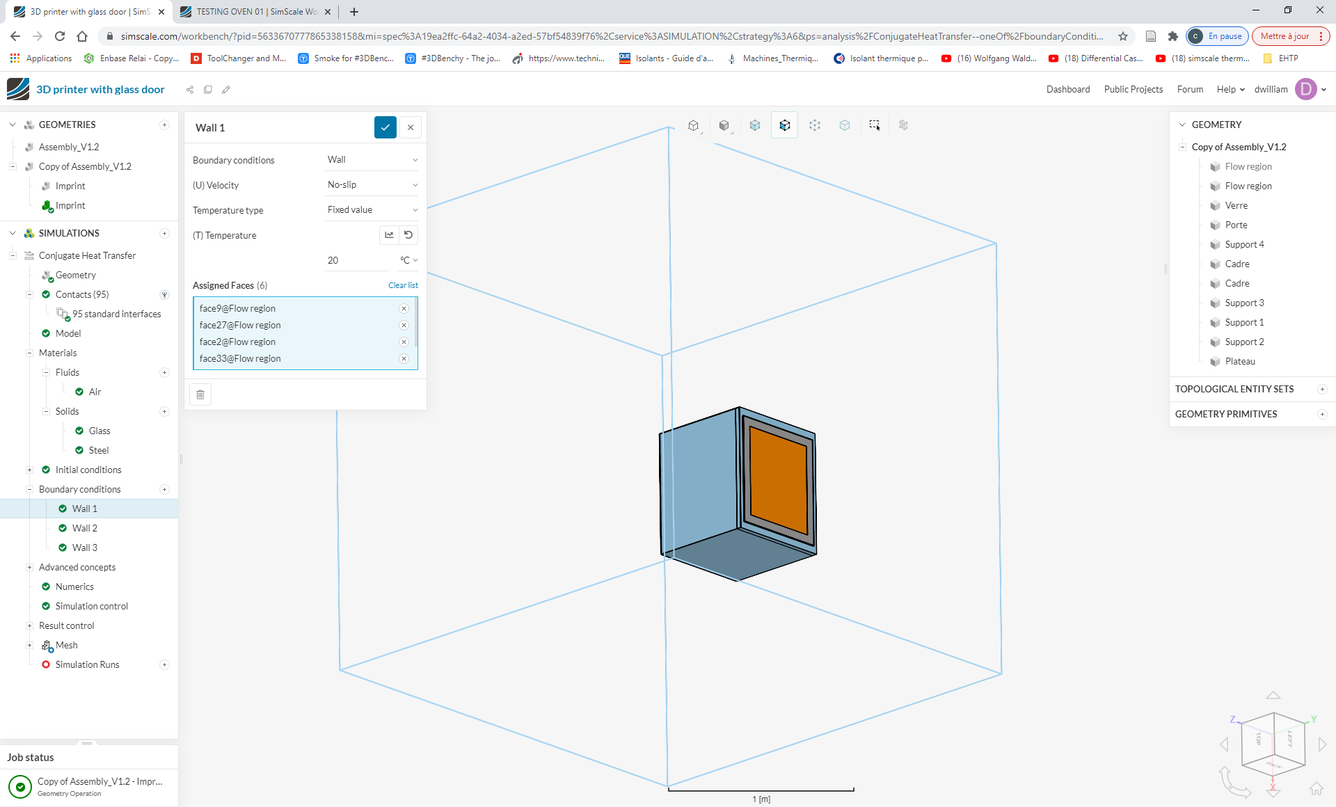
Furthermore, as the documentation page that I linked states, defining a boundary condition to an interface (i.e. the interface between two volumes) overconstrains the system and causes the error that you are facing.
In short, the only faces that can receive a boundary condition are the boundaries of your geometry (i.e. the 6 external bounding box faces of your flow region). The other faces cannot receive a boundary condition.
I’d suggest that you go through the LED natural convection cooling tutorial, which should provide you good insights with respect to the set up.
 This is probably because some faces belong to more than one region (as they are in contact).