Hi everyone
I’m trying to simulate a CFD flow over a rotating propeller but I’m not too sure about the rotating zone which I’ve to create. Any ideas? https://www.simscale.com/workbench/?pid=4390718115295170910#tab_0-0
Thanks
Melissa
Hi everyone
I’m trying to simulate a CFD flow over a rotating propeller but I’m not too sure about the rotating zone which I’ve to create. Any ideas? https://www.simscale.com/workbench/?pid=4390718115295170910#tab_0-0
Thanks
Melissa
Hi @msheu!
I will have a look at your project later on and will come back to you with some suggestions.
Best,
Jousef
Hi again @msheu!
If you want to use MRF zones you would need to build another “cylinder”. The following project demonstrates well what you have to do in order to have the geometry set up in a correct manner: Propeller CFD Simulation
Please also make sure to get rid of the overlapping surfaces in the middle of your propeller. Let me know how things go.
Best,
Jousef
Hi @jousefm
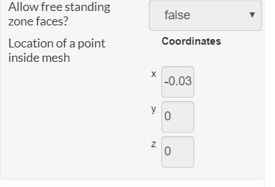
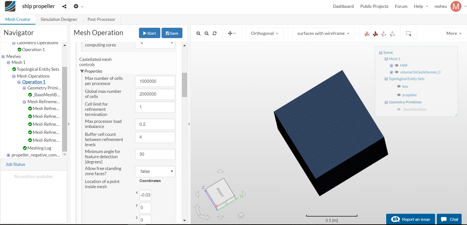
I’m following closely to the ship propeller case. However, how do I locate the point inside the mesh under the hex-dominant parametric function?
Thanks
Melissa
Hi Melissa,
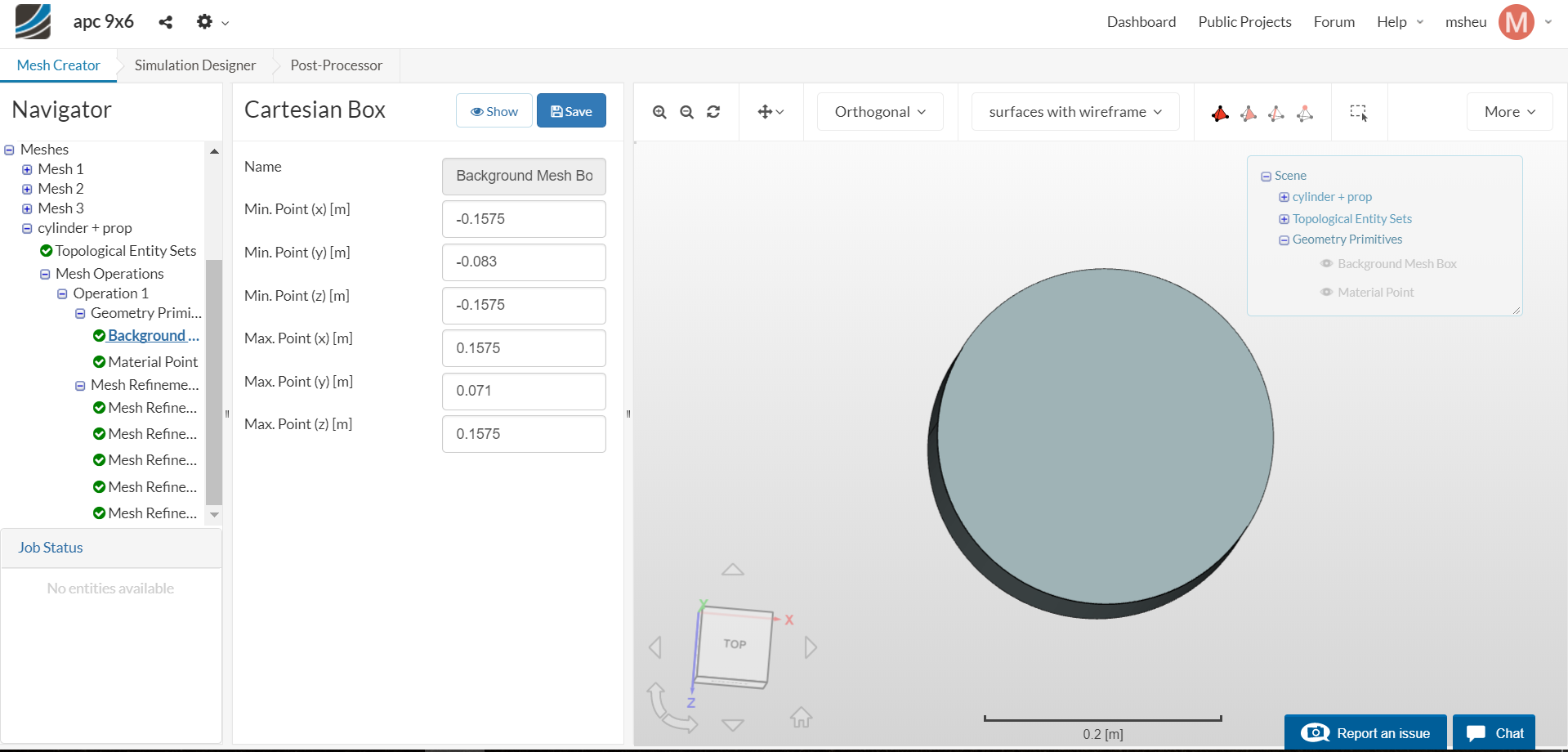
Under geometry primitives, there is a material point primitive.
I looked at your project and I’m not sure it has imported as the correct size, do you know it is only 0.28mm in the biggest dimension?
Kind regards,
Darren
Hi Darren
You mentioned material point primitive, but I can’t seem to delete it and change it to a cartesian box like how propeller case. The background mesh box and material point are mandatory geometry primitives. Any ideas?
Also, I have removed the scaling factor in my geometry.
Thanks
Melissa
Hi Melissa,
Yes they are mandatory for both internal and external flows, otherwise we wouldn’t know where to start and finish the meshing in space, or which region to mesh.
For this case you will have a multi region mesh, I normally put my material point outside the rotating region but inside the bounding box.
Kind regards,
Darren
Hi Darren
Do you know how to remove the cylinder in my meshing?
Thanks
Melissa
Hi Melissa,
Not sure what you mean by remove the cylinder, but I had a look at your project and it looks like you haven’t defined the cylinder as a zone. To do this you need select the faces of the cylinder and enable the cell zone option. Is this what you mean?
If not could you maybe show some images to demonstrate the issue?
Kind regards,
Darren
Hi Darren
Where do I go to enable the cell zone option? Because I’m new to this platform and I would appreciate it if you would show some images to demonstrate what you mean.
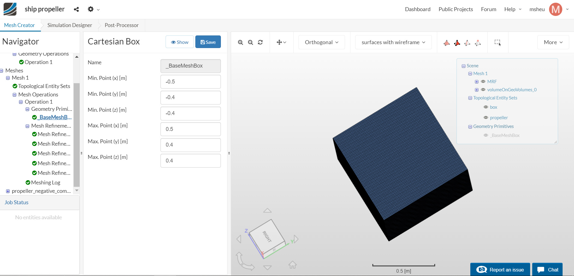
I’m modelling after this https://www.simscale.com/workbench/?pid=2122901296744115844#tab_0-0 and under his "Geometry Primitives’, he only has a cartesian box with his ship propeller inside it. He basically removed the cylinder which was present before that. So, I’m wondering how do I remove my cylinder?
Thanks
Melissa
Hi Melissa,
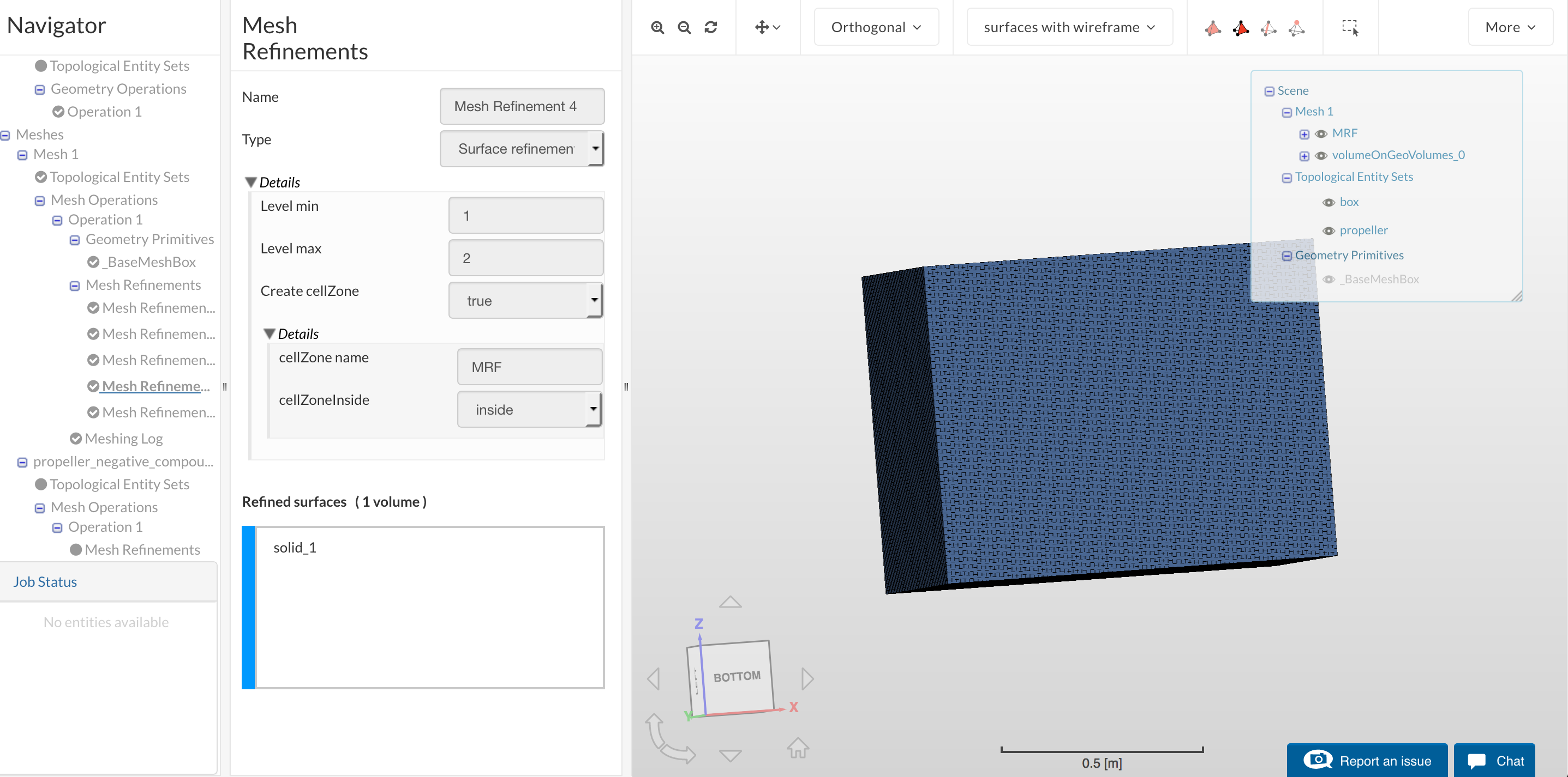
The cell zone is created by selecting all surfaces within a surface refinement and enabling the cell zone option. Surface refinements can be added through the refinement section of the node tree, here is a screenshot of your example:
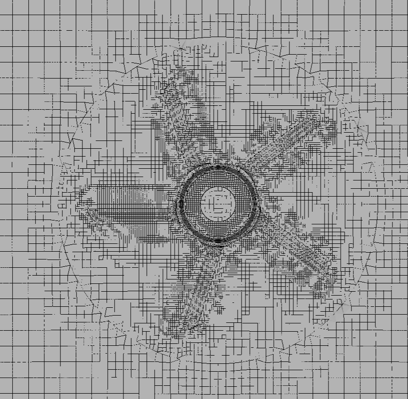
He didn’t remove the cylinder he used it to create the cell zone here:
Where you can just see the mesh cell zone interface around the prop.
Hope this helps,
Darren
Hi Darren
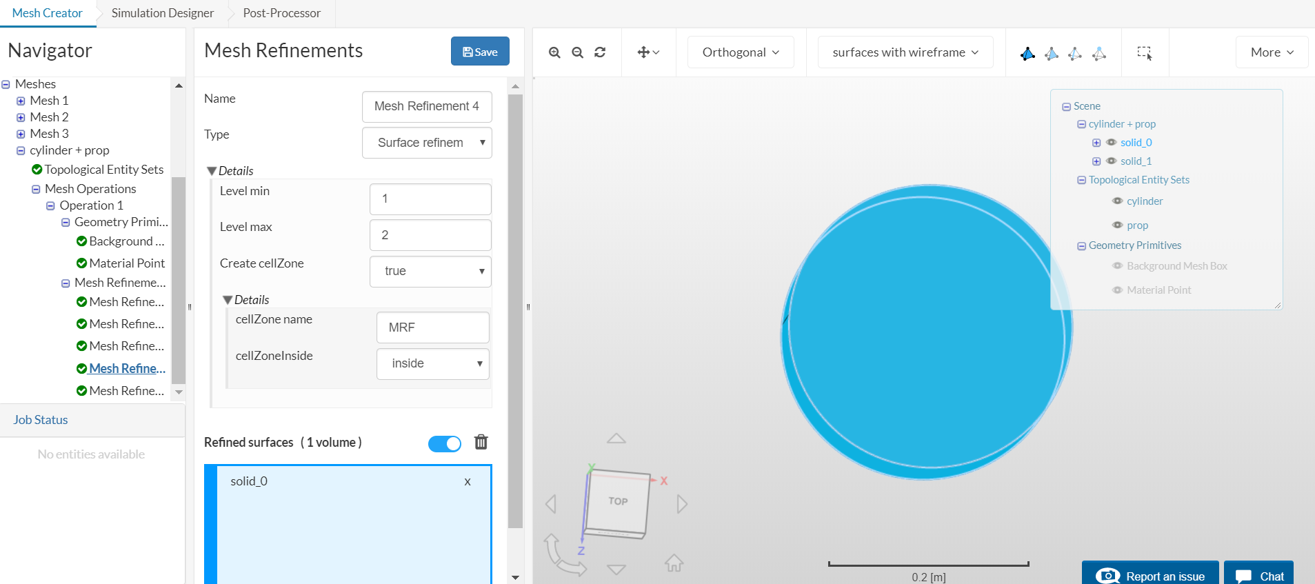
I’ve already enabled the cell zone option
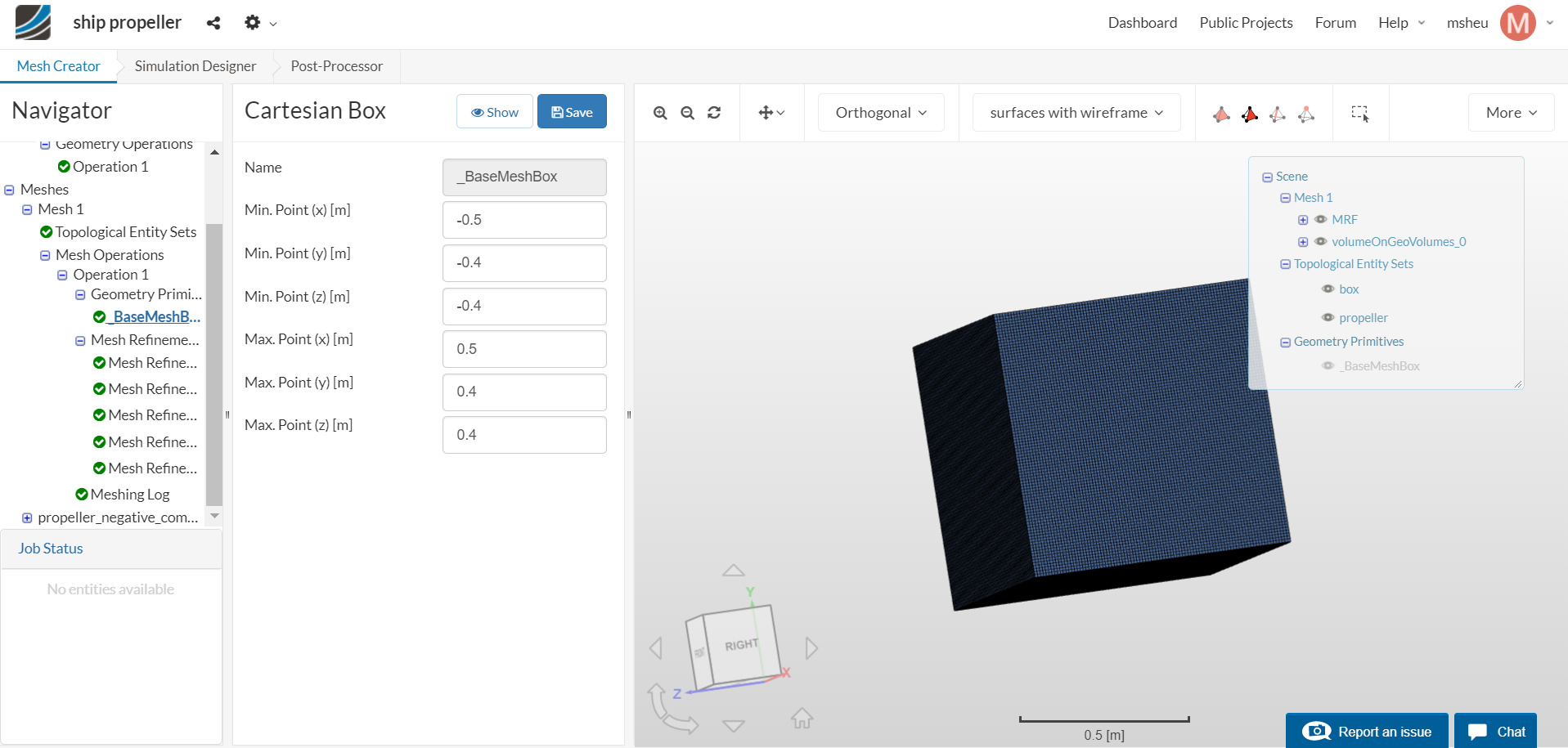
but I still don’t get why the cylinder and material point didn’t ‘disappear’ when I’m setting my background mesh box like his did.
This is his:
Any ideas?
Thanks
Melissa
Hi Melissa (@msheu)!
I think there might be a slight misunderstanding. You still need the bounding box as well as the material point to define your fluid domain. How else would you assign your boundary conditions later on? This is absolutely necessary as Darren (@1318980) already mentioned to define if you have an internal or external flow analysis. Does that make sense to you? Hope that explains it a bit. Feel free to ask if you want to know something or are still not sure about settings inside the workbench. Trying to help you out wherever we can 
Best,
Jousef
Hi Jousef
Thanks for clarifying but I’m just wondering why for his project, under ‘Geometry primitives’, only the base mesh box is shown? Where did the material point go? And when he applied that function, only the propeller is present in the box, or so it seems. Where did the cylinder go?
Regards
Melissa
Hi @msheu!
I am currently running a new mesh. I assume that you are using the “old” layout which created a bit of a confusion in this discussion. I will post the finished mesh asap to be at the same level and we may then continue with your simulation.
Update: Shared.
Best,
Jousef
Hi Jousef
I’ve already meshed my propeller. Can you help me check and see if this is what you meant?
Thanks
Melissa
Hi Melissa, in discussion with @jousefm as he noticed an issue where some odd behaviours occurred. However I have a successful mesh for you to use:
You might want to refine further the propeller, however, the basic setup is there, I might also be tempted to increase the bounding box size but that is up to you.
Good luck,
Darren
Hi Melissa, I would recommend using the setup as a basis only and adjust it to your need, the example isn’t what I would call simulation ready simply a good working starting point.
That said I would expect a mesh downloaded and reuploaded from SimScale to not have an issue, I’ll look into it and raise a ticket if necessary.
Kind regards,
Darren
Hi Melissa, just following up on this. After downloading the mesh I left it as a zip and reuploaded it with the OpenFOAM format and it all worked no issue.
Maybe you unzipped it or specified a different format?
Kind regards,
Darren