Hi Simscale Community,
I’m trying to set up a validated simulation environment for further testing using Ahmed Body with 25° slope.
I followed user Retsam’s Project pretty much to the point.
The only differences I can think of are:
-I didn’t use a rounded velocity inlet
-My coordinate system was twisted, which I adjusted for
-Center of rotation, probe points and the split faces for the finer mesh areas weren’t exactly the same, but close.
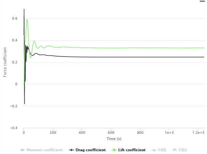
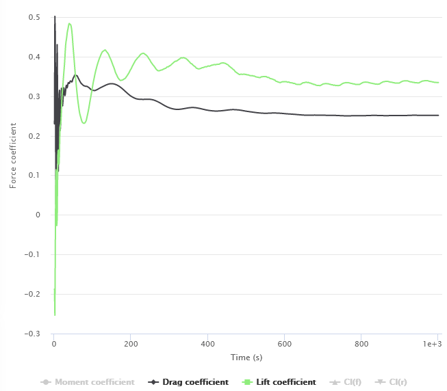
However, while Retsam’s results show a Drag Coefficient of 0.298 (experimental: 0.299) , my results are 0.246.
Another observation I made is that my Lift Coefficient of 0.329 is much closer to the experimental result of 0.345. As a side note, for my further studies I will only use the Drag Coefficient.
I used Retsam’s project as a current best practice. Are there any new recommended practices that have changed since then? I noticed he didn’t use the Hex element core feature, which I suppose would be more efficient? That said, I’m new to CFD with no prior experience.
Here is a Link to my Project
Best,
Jan
Hi!
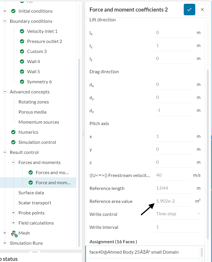
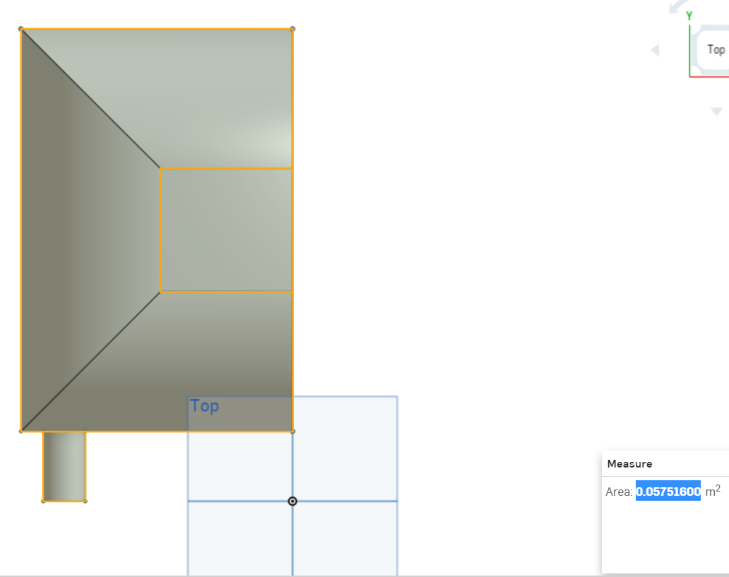
I have a question: how did you estimate the reference area value for the drag/lift coefficients control?
When having a look at it, I’m getting a different value than yours:
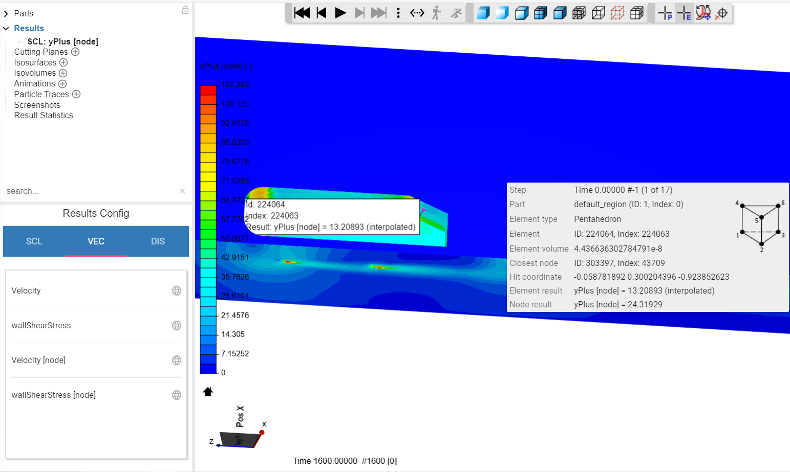
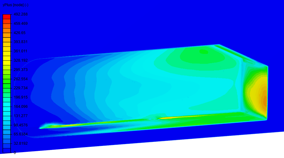
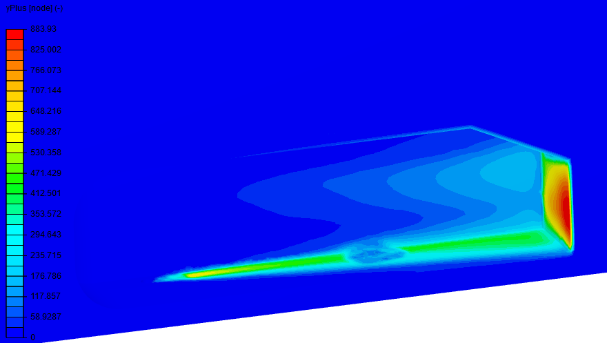
I would also recommend adjusting the layer settings a little better. Currently we have y+ values which are too low:
Having such low y+ values in the region where the air separates will definitely cause issues. Basically the boundary layers need to be a little thicker (30< y+ < 300 if you’d like to use wall functions) or much finer (y+ < 1 if you want to use full resolution).
PS: a validation case on the Ahmed Body was released not very long ago.
Cheers
Thanks for replying Ricardopg!
I used the value that Retsam used - just to reach the same result he did. Reference area of the whole Ahmed Body is about 0.115m², which is in accordance to your result. For further testing, I will use the right measurement.
But already in the forces plot I get very different results to Retsam.
Thanks, I didn’t check this before. I will increase the BL.
Retsam’s values look very similar to mine, I still wonder where that huge difference in Cd comes from.
My guess is that it’s some obvious oversight on my end, but so far I haven’t spotted it…
I will try to use the linked validation case next. The reason I didn’t use it before was the much higher cell number.
Best,
Jan
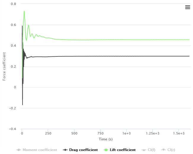
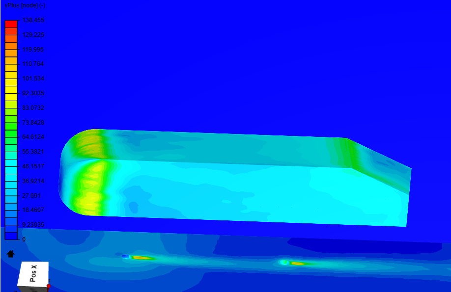
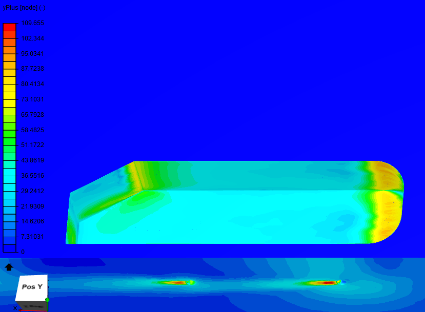
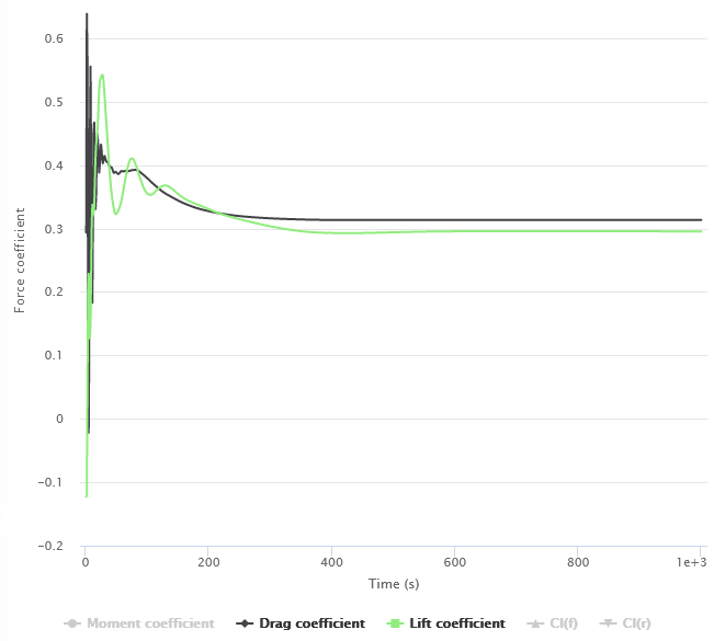
I did two more runs with 5x increased BL and 10x increased BL. I haven’t changed to the right reference area yet (the results are about 2.6 % off).
Most of the values seem to be between 30 to 300, especially in the BLx5 run, with a few exceptions on the front and back.
The results are vastly different and nowhere near the experimental values of 0.299.
The run with 5x increased Boundary Layers, where y+ seems to be mostly right, is around 0.25 again, just like my first run. What am I missing here? To just play around with the BL size to get to the desired results seems pointless.
I understand a good mesh is vital. To me, the mesh looks good enough and the mesh quality given in the Meshing Log should be fine too. Or do I have to further improve it somehow?
I’m also trying to set up the validation case. I noticed a lot of the input parameters are very different to the preset parameters (P, k, omega, even nu and rho in the material settings) - is this just to account for inaccuracies with OpenFOAM and to achieve “better” results or is there another reason?
(Link to my project.)
I’m still new to this and assuming I’m making rookie mistakes here. Can someone point me in the right direction?
Best,
Jan