I am simulating a fan duct (part fan for a 3d printer). Created the duct, the box around it, generated the open inner space and ran simulation using velocity inlet and pressure outlet gives nice results.
Being unsure whether specifying velocity or pressure at the inlet (a blower fan generates only so much pressure and restricting the outlet will thus reduce flow, I am however unsure whether velocity inlet would take this into account) would make a difference. I used the exact same setup and changed the velocity input to pressure input (keeping the pressure output). The simulation runs, I get into the solution fields workflow.
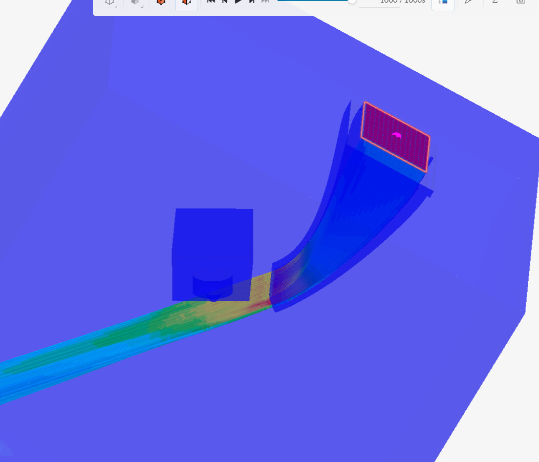
A bit difficult to capture in a screenshot, thats Why I put the link to the actual simulation. The first one I selected the inlet to get a particle trace. However on the second one if you rotate the box you see it has selected the internal face that was accidentally seen trough the inlet.
When I do the exact same thing in a previous simulation I do get the correct spot selected. The only difference is that I specified a velocity inlet in this case. In the case above a pressure inlet was selected. Other than the pressure vs velocity inlet there is no difference.
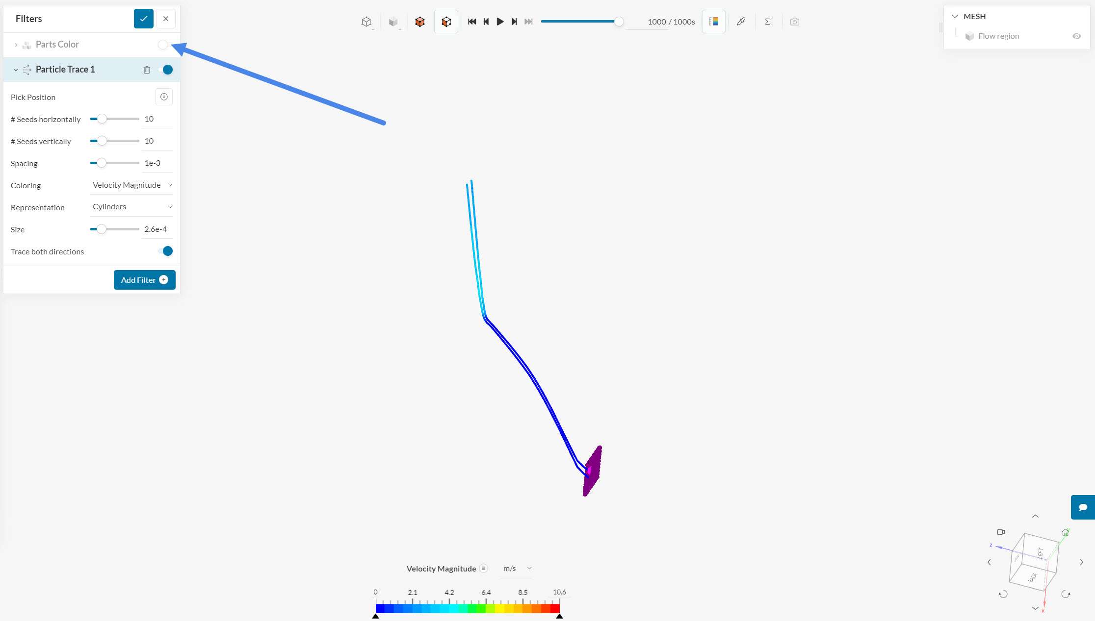
It is normal that the model disappears and only the streamlines stay visible when choosing the seed face. If you wish to view the model too, make sure you toggle on the Parts Color: