Aerospace Workshop 2 Session 1: Optimization of a wing - Part I Meshing
Recording
Aerospace Workshop II feat. EUROAVIA (Session 1) ― Aerodynamics of an Aircraft Wing
Exercise
The task is to optimize an aircraft wing with and without winglet.
For these cases we will use the Hex-Dominant Parametric meshing operation which provides full functionality to mesh complex geometries. The tutorial below will provide detailed steps on how to use each meshing feature to get a well resolved mesh.
Step-by-Step
Import the project by clicking the link below. (Crtl + Click to open in a new tab)
Click to Import the Homework Project
Once the project is imported, the workbench is automatically opened. Then follow the steps below for setting up an incompressible flow simulation .
Mesh-1 (Aircraft wing)
Please select the Aircraft_wing geometry in the left-hand side of the screen. Proceed by clicking on Create Simulation.
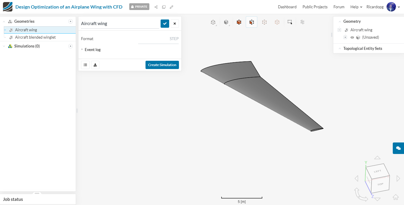
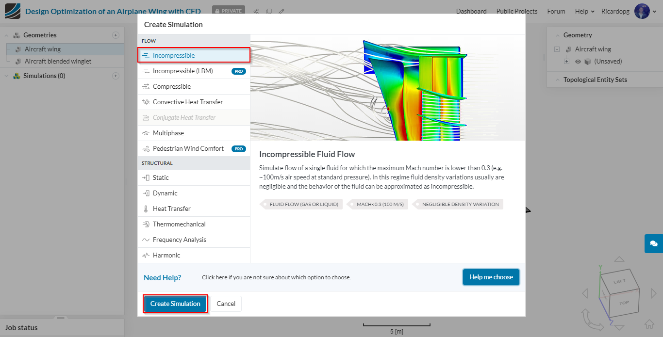
In the window that appears, select Incompressible and Create Simulation. The simulation tree will be loaded in the left panel.
Creating a mesh
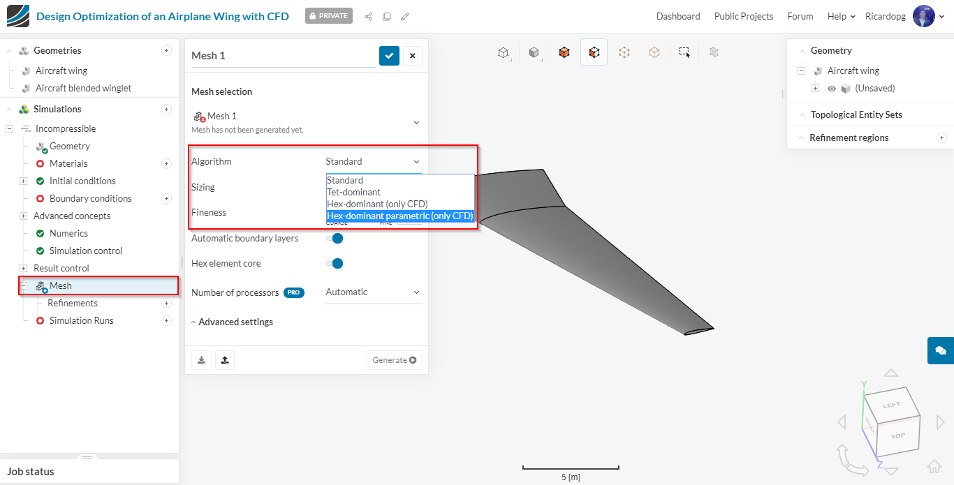
In the simulation tree, navigate to Mesh. The Standard meshing Algorithm is automatically selected. Please switch the Algorithm to Hex-Dominant Parametric (Only CFD). In this algorithm, cells are mostly hexahedral. Prisms, polyhedral, pyramids and tetrahedral cells may also be present in smaller quantities.
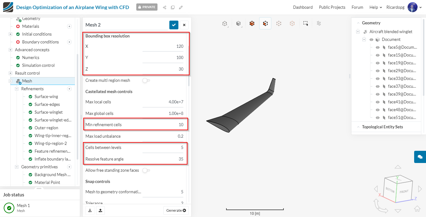
Adjust the Bounding box resolution as shown below:
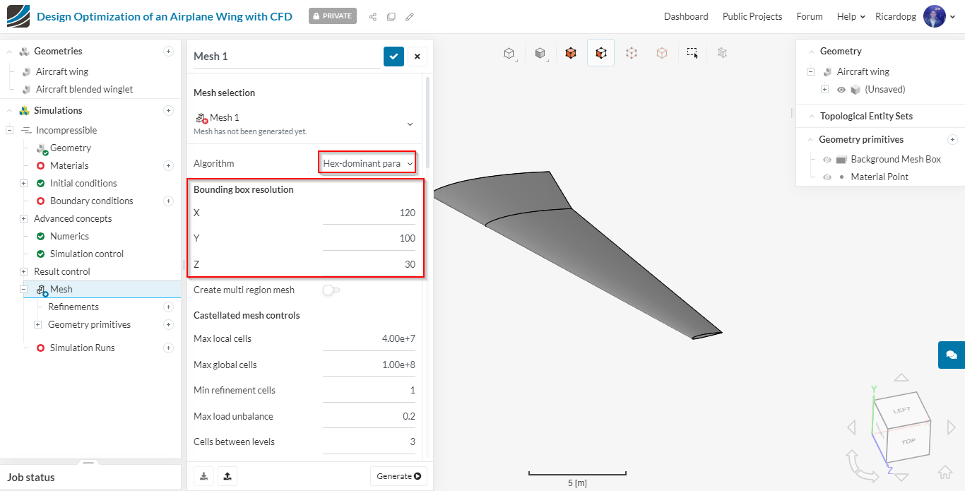
Now, in the simulation tree, under Mesh, please expand Geometry primitives. Two primitives are already set: Background Mesh Box and Material Point. Click on Background Mesh Box and edit the inputs as shown below. It is important that the domain boundaries are far from the wing, so they won’t interfere in the results.

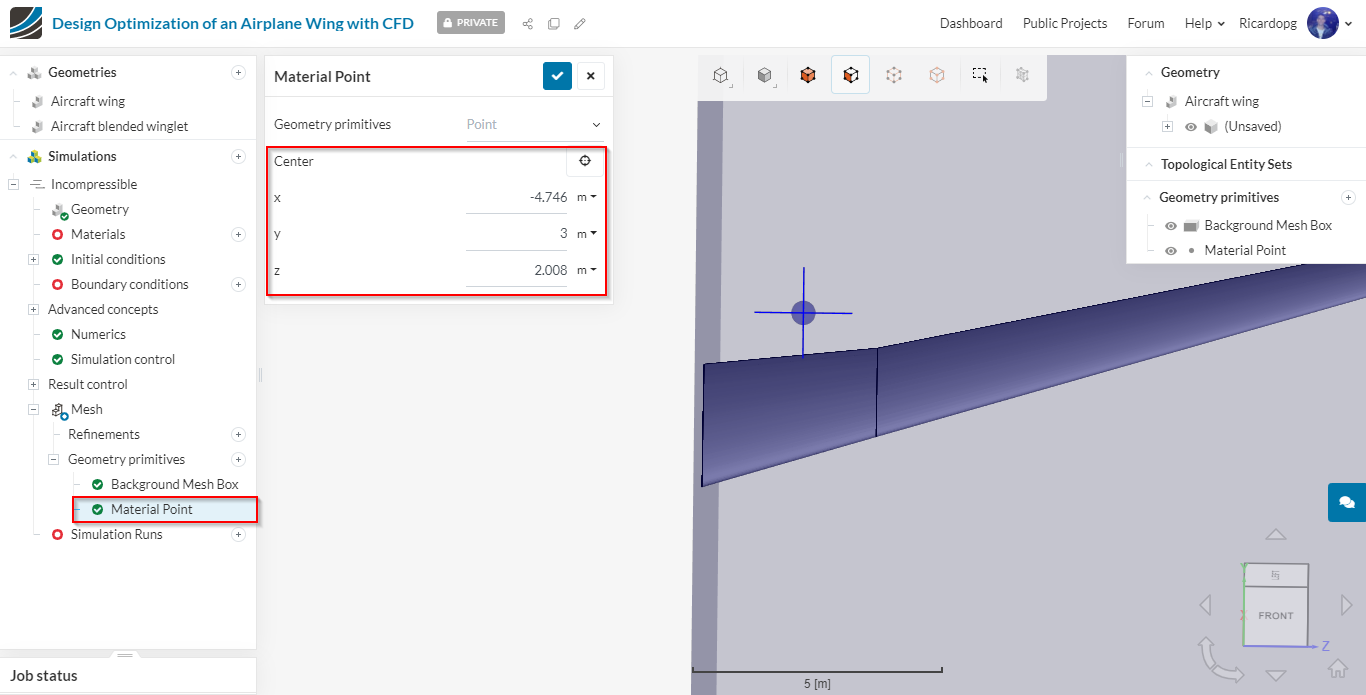
The Material Point tells the meshing algorithm which region will be meshed. If the material point is located inside the wing, only the inside will be meshed. As we are interested in the outside, we have to adjust the coordinates of the material point. For example, the following coordinates work:
Further primitives
- We will create 4 geometry primitives that will be used for mesh region refinements later in the meshing setup.
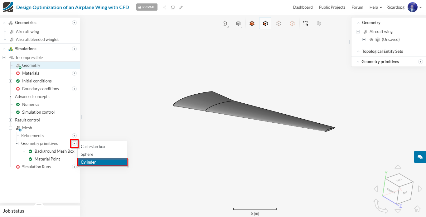
- To create a new primitive, click on the + icon next to ‘Geometry primitives’ and then select a ‘Cylinder’.
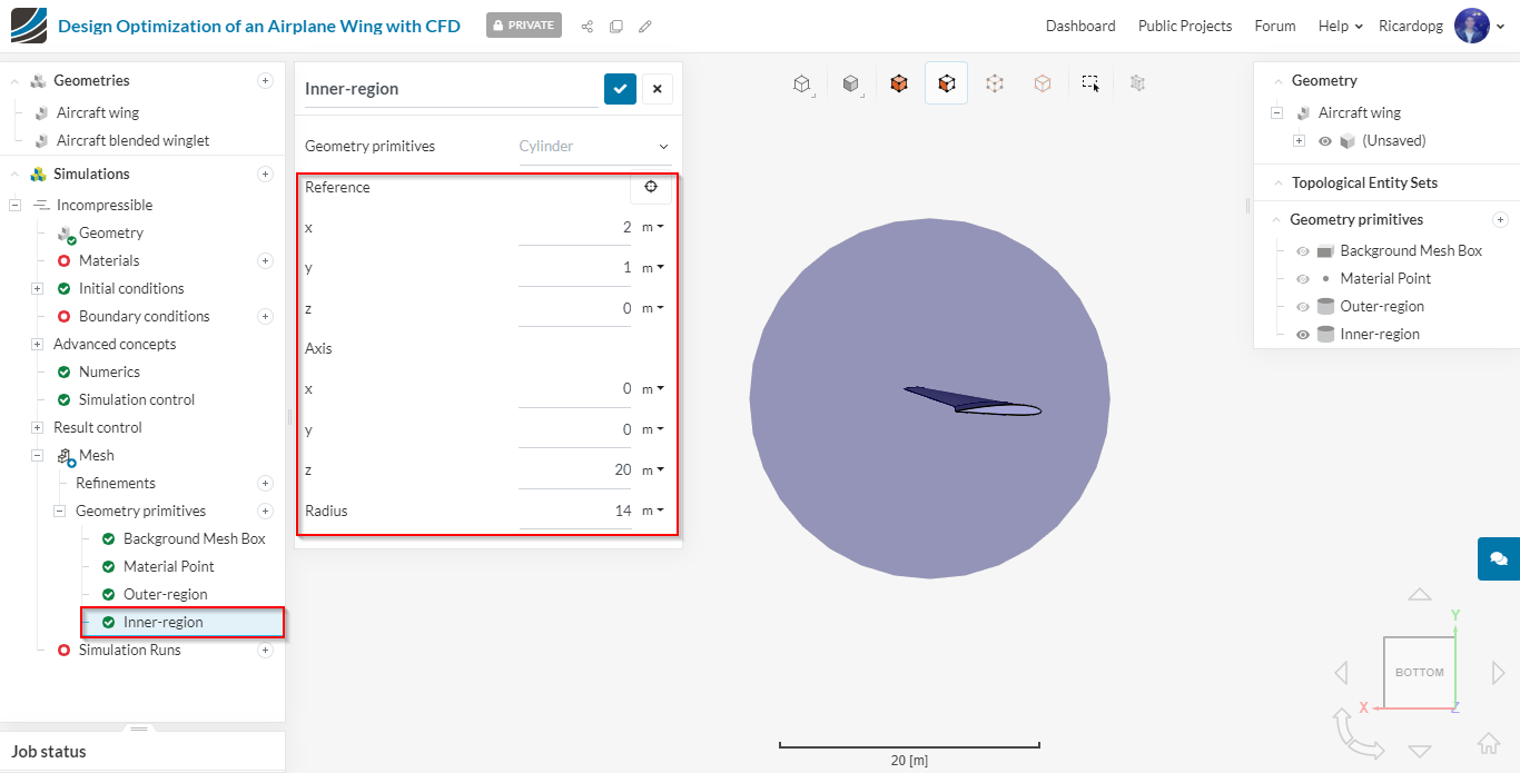
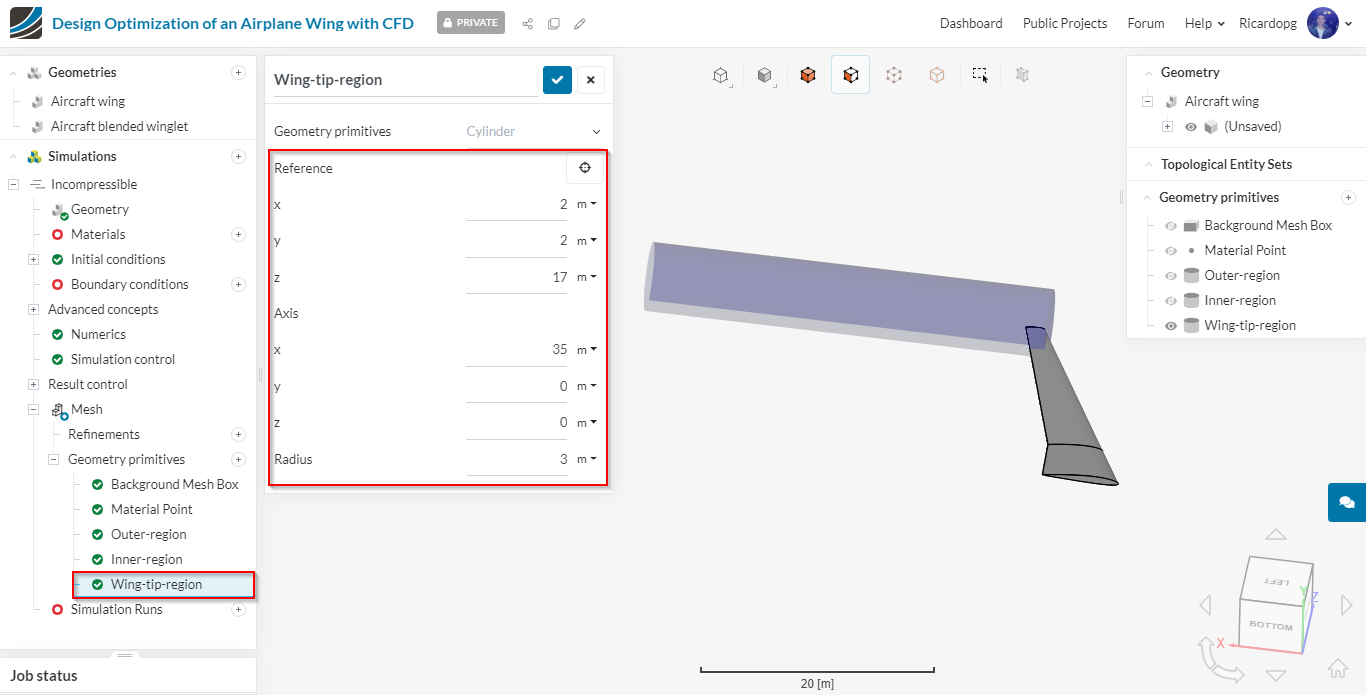
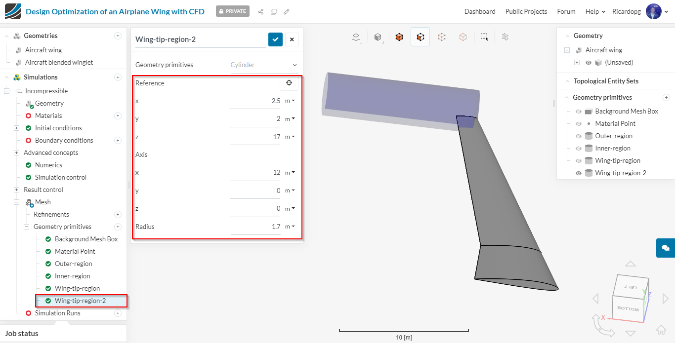
The table details the parameters for the 4 cylinder entities that are shown in the figures below.
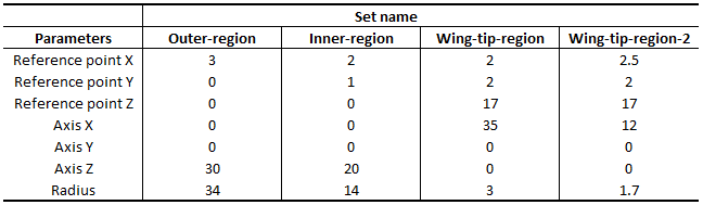
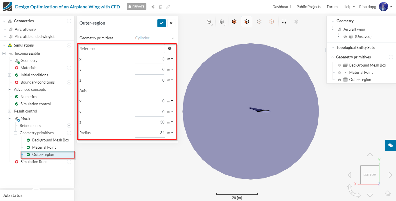
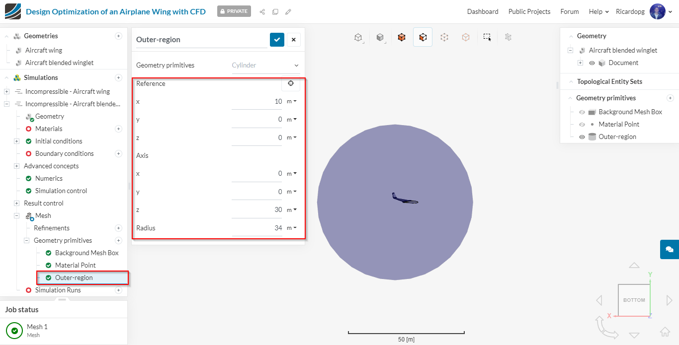
Outer-region geometry primitive:
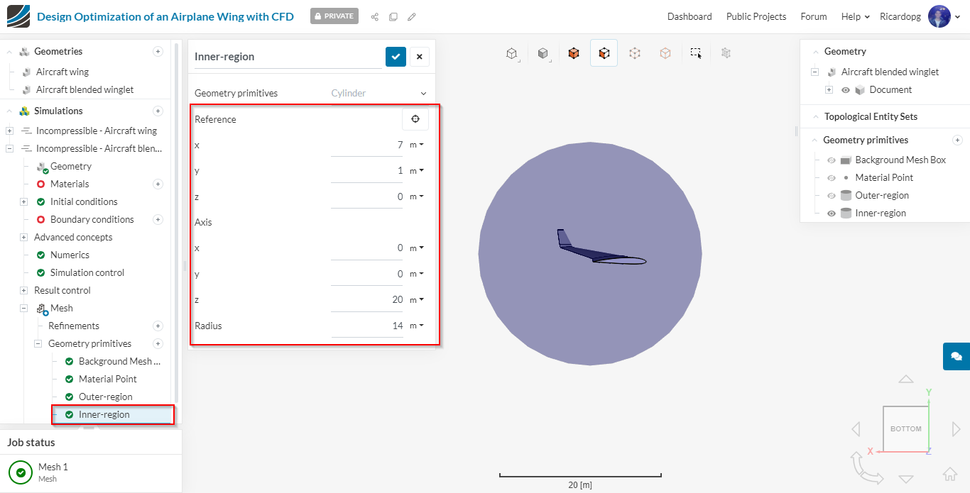
Inner-region geometry primitive:
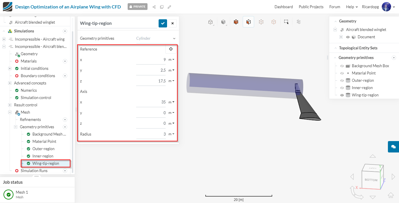
Wing-tip-region geometry primitive:
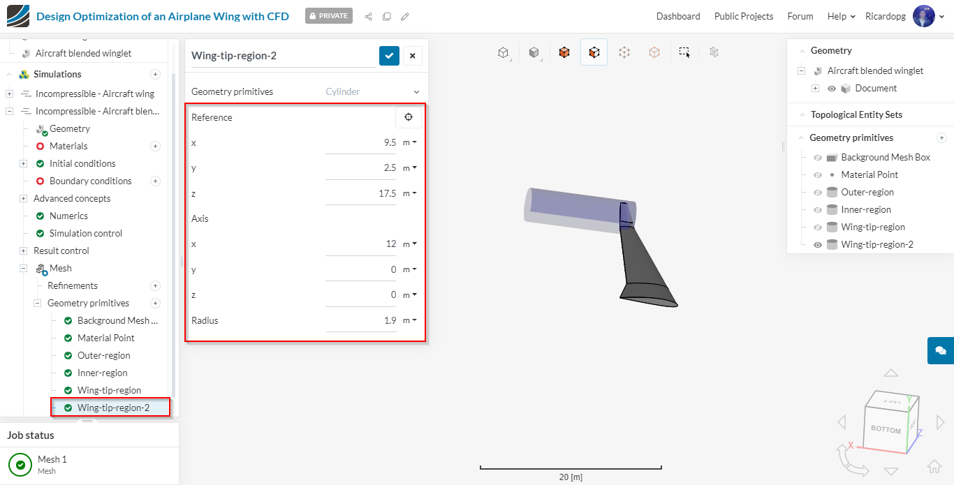
Wing-tip-region-2 geometry primitive:
Mesh Refinements
We will now add the necessary mesh refinements for the previously created geometry primitives, aswell as some face sets. To create a mesh refinement, click on Refinements just under Mesh and select the desired refinement type.
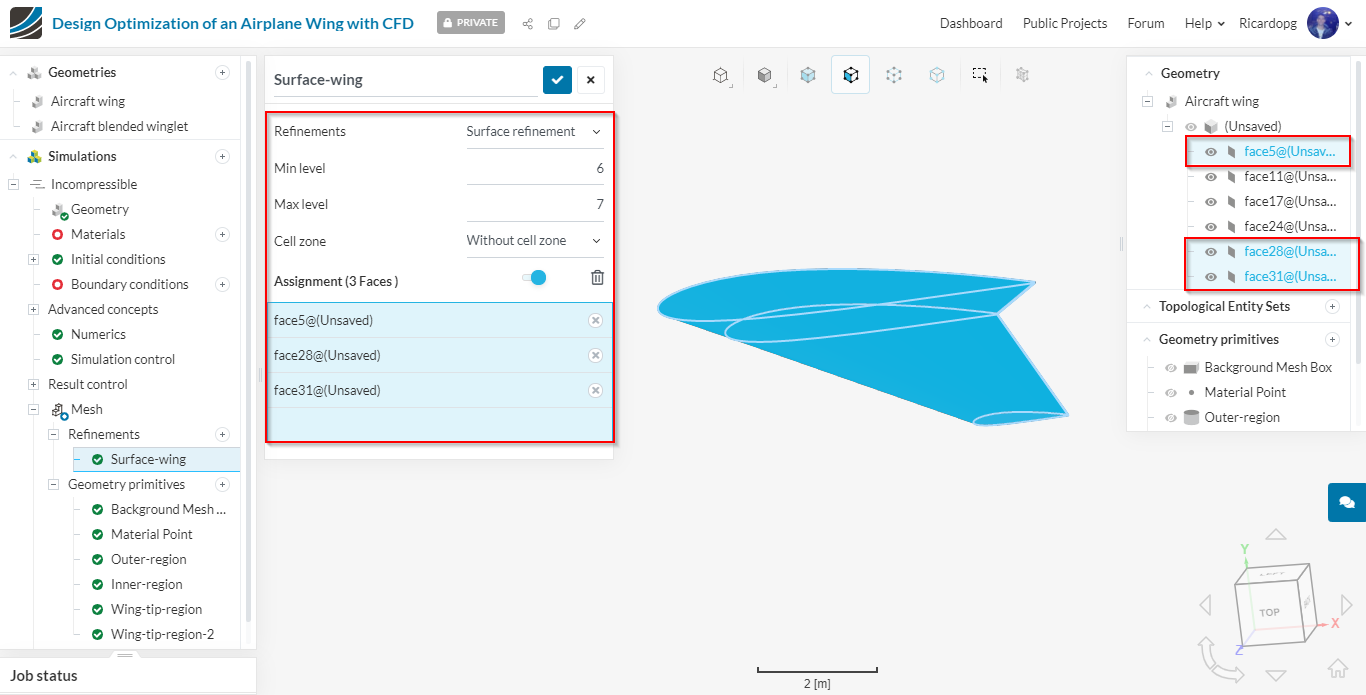
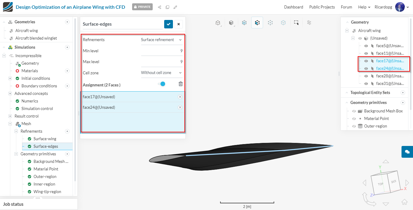
Surface refinements:
Surface-wing: this refinement will be used to refine the bigger surfaces of the wing.
Surface-edges: this refinement will be used to refine the small surfaces of the wing.
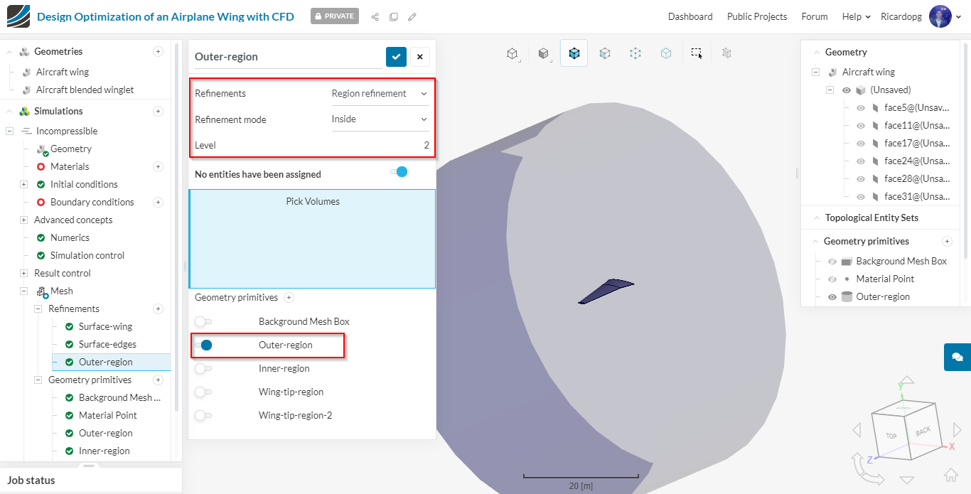
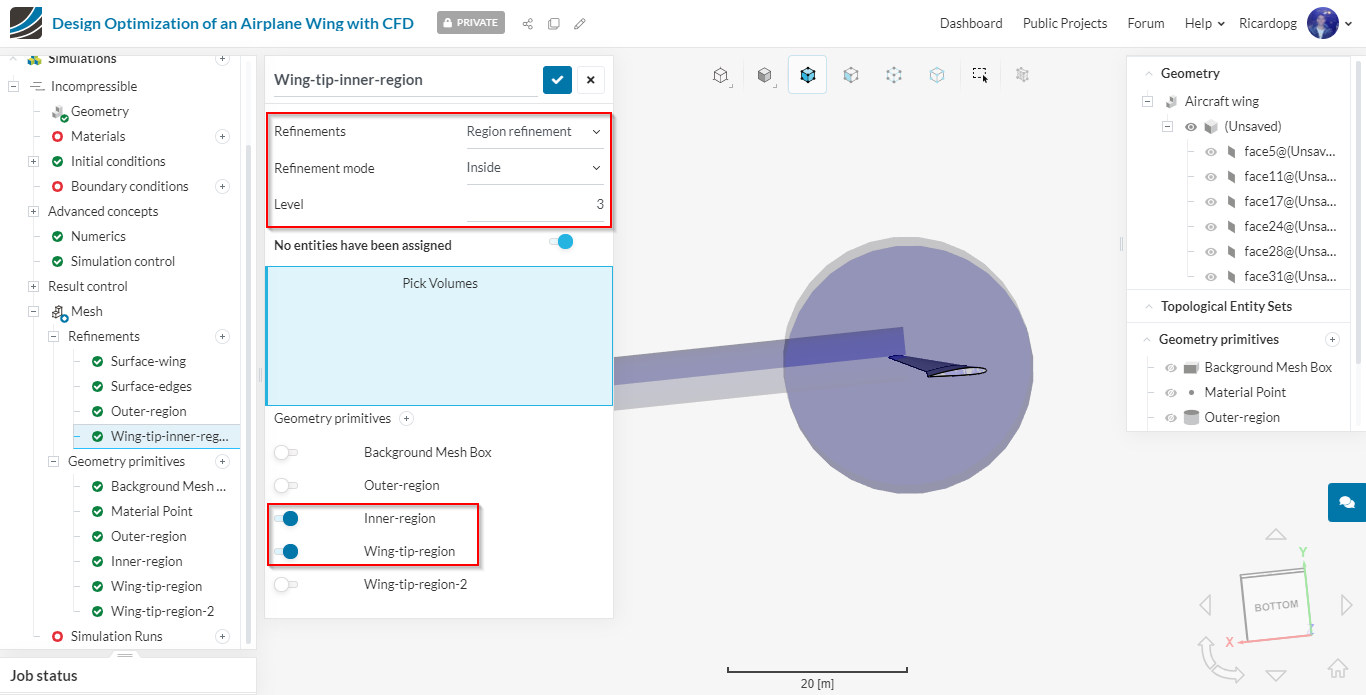
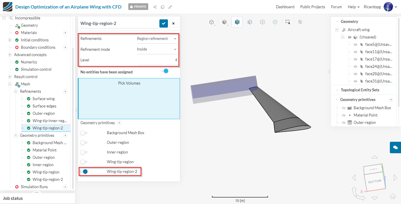
Region refinements: these refinements will refine the volume mesh. We will create 3 region refinements and assign them the previously created geometry primitives.
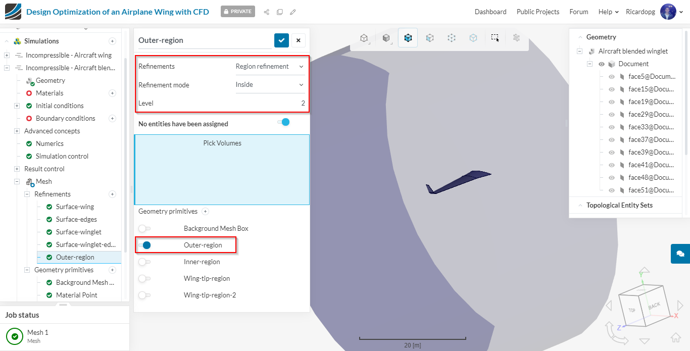
Outer region
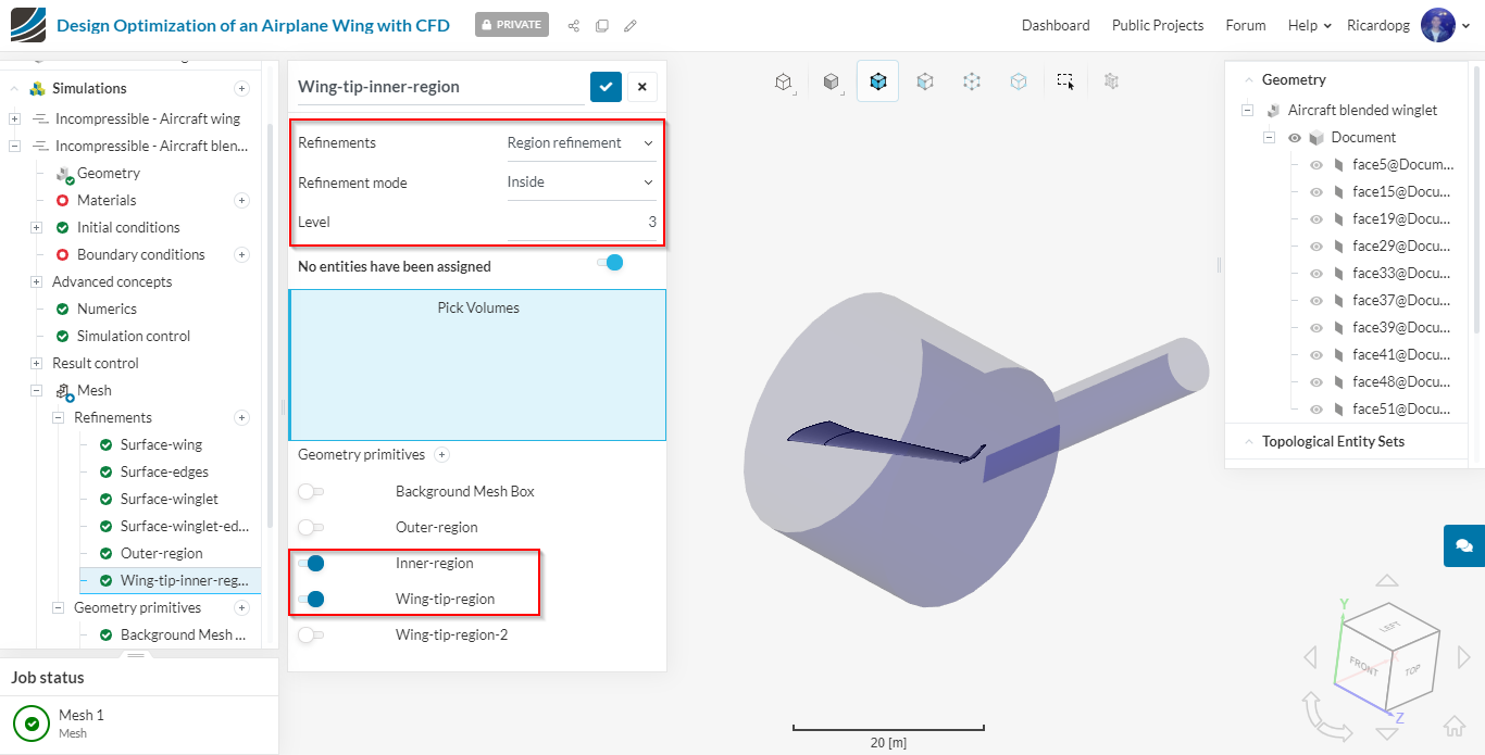
Wing-tip-inner-region
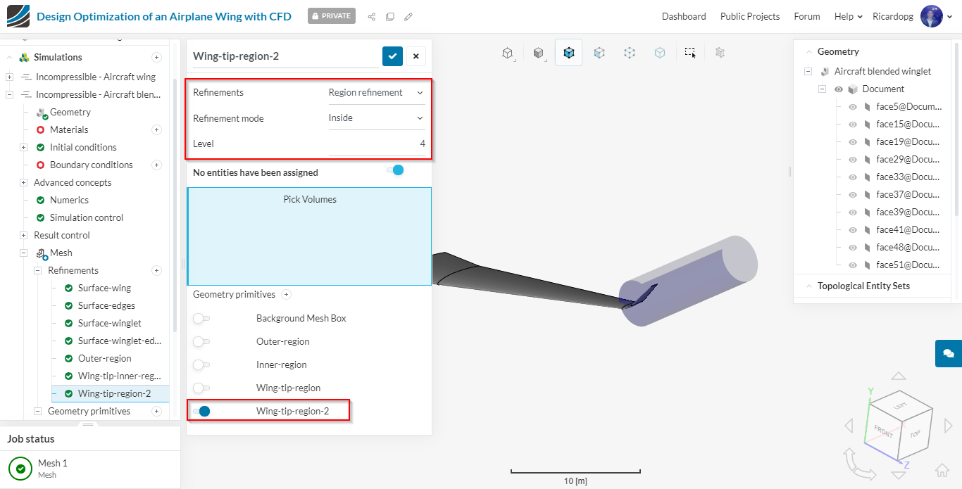
Wing-tip-region-2
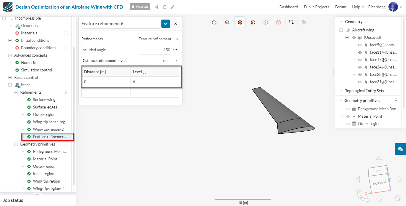
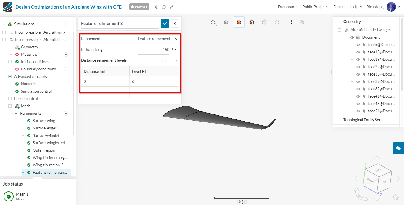
Feature refinement: this refinement will refine the area near edges. This is important to capture sharp corners.
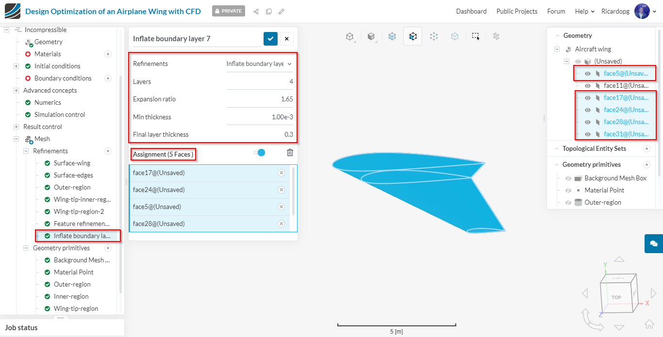
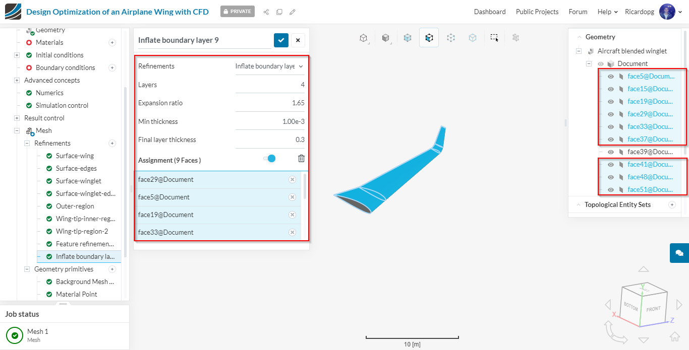
Inflate boundary layer: the layer refinement is important to capture the boundary layer near the wall. This will create layer cells following the surface curvature near the walls.
So please add an Inflate boundary layer refinement and set it up as follows:
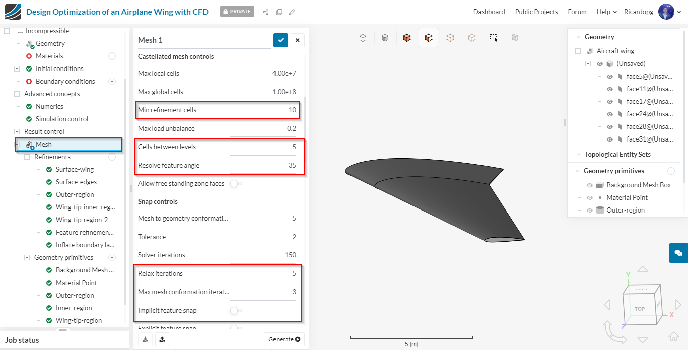
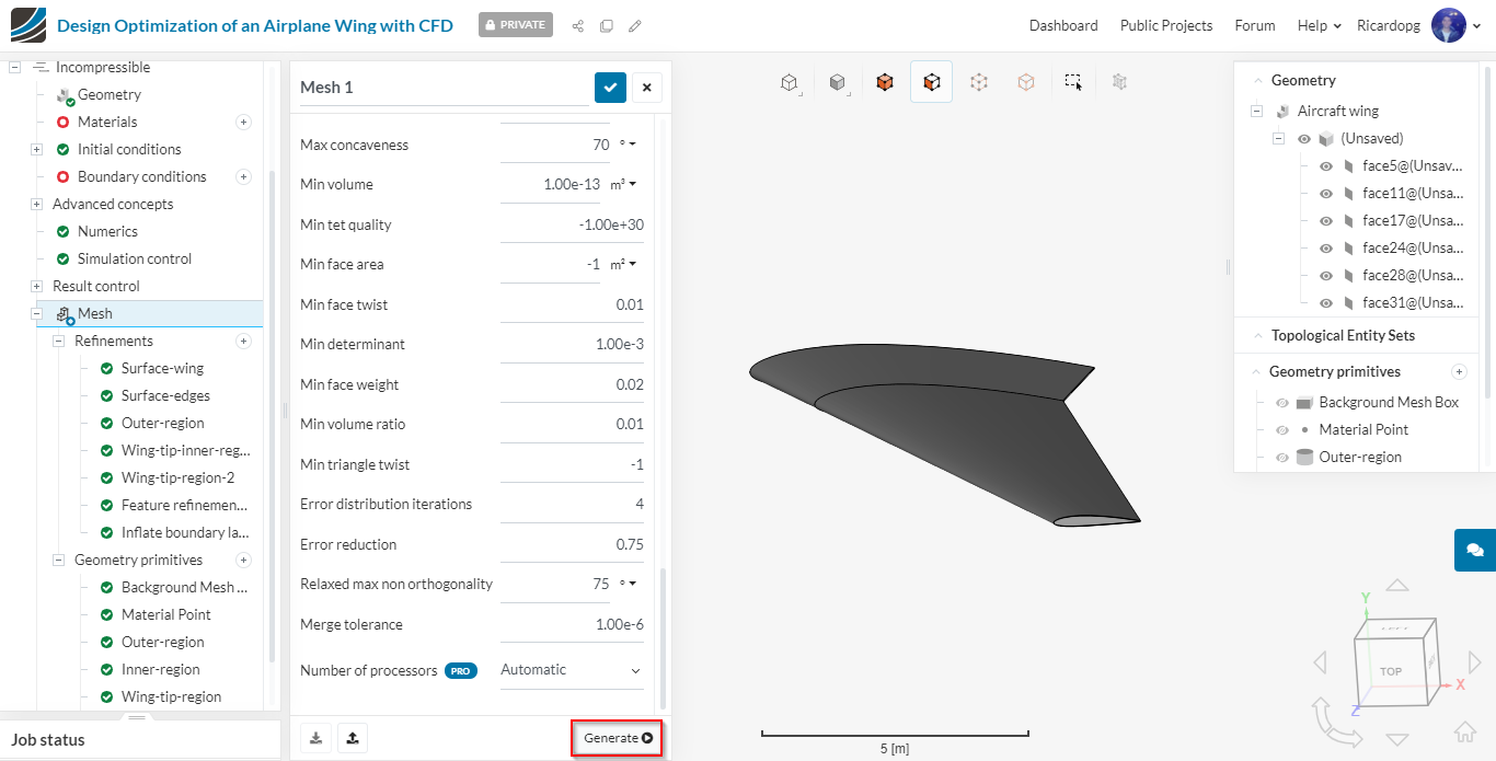
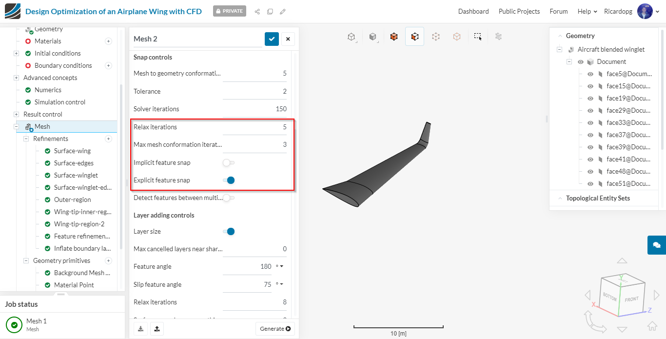
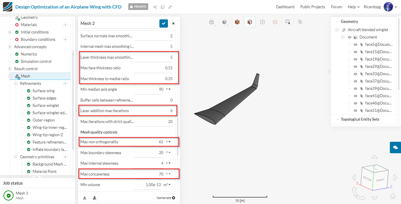
Lastly, we will change some parameters in the advanced settings by clicking on Mesh operation and scrolling in the settings panel as shown in figures below. This will help to get a good quality mesh for a complex geometry and get the appropriate y-plus value for the cases.
Only the highlighted parameters are different from default:
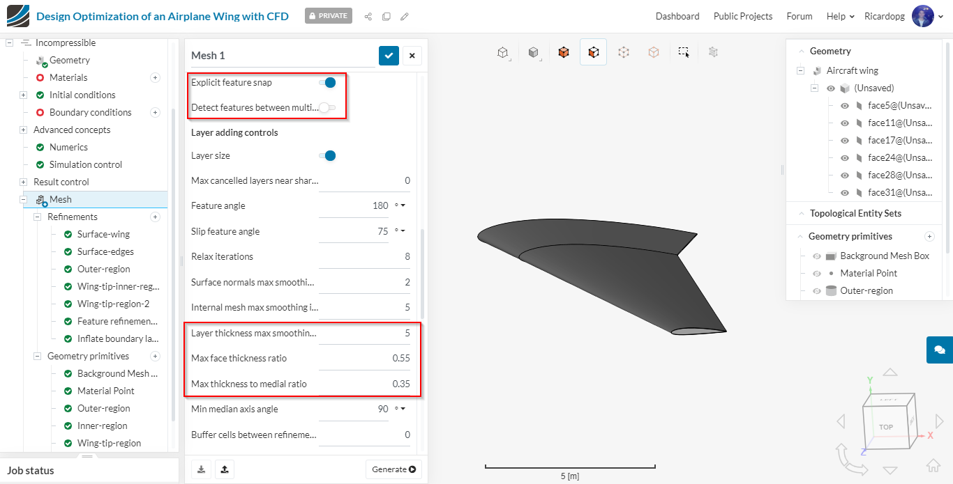
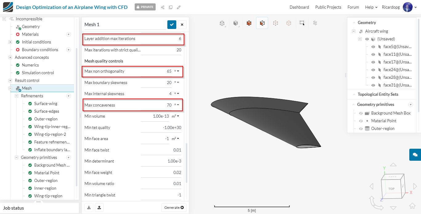
Remember to save the settings after changing the parameters by clicking on the blue mark.
The number of processor used is automatically determined based on the size of the job. Therefore, we can proceed to clicking Generate to create the mesh.
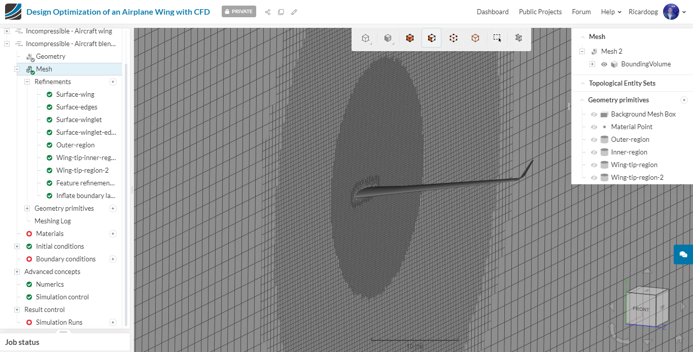
After the mesh finishes running, click on Use Mesh as Domain.
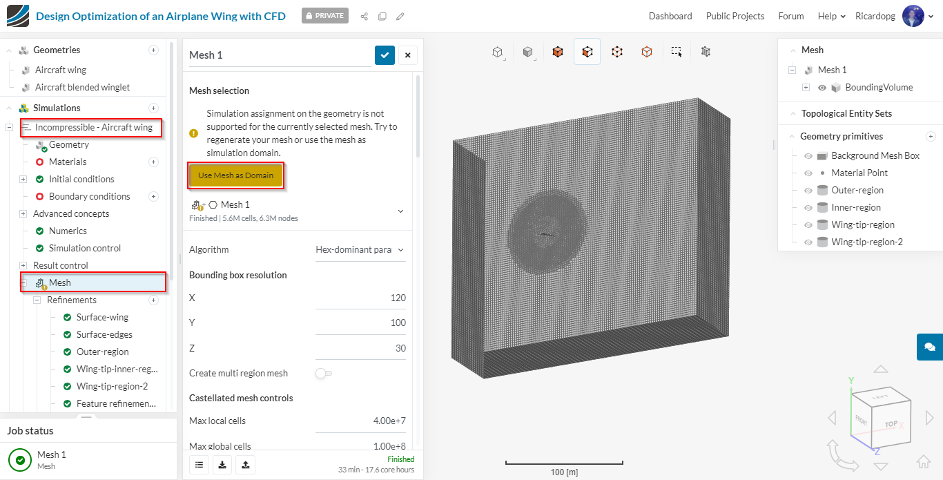
You can visually inspect the mesh aswell as check the Meshing log in the simulation tree for information regarding mesh quality.
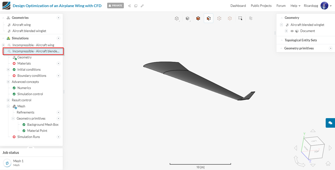
Mesh-2 (Aircraft blended winglet)
For the second mesh, please follow the same procedures as the previous case till the creation of Geometry primitives. By the time the geometry primitives are about to be created, the simulation tree should be looking like this:
Geometry primitives
The table below shows the parameters for the 4 cylinder primitives that will be created.
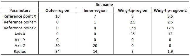
Outer-region geometry primitive
Inner-region geometry primitive:
Wing-tip-region geometry primitive:
Wing-tip-region-2 geometry primitive:
Mesh Refinements
We will now add the necessary mesh refinements for the previously created geometry primitives, aswell as some face sets. To create a mesh refinement, click on Refinements just under Mesh and select the desired refinement type.
Surface refinements:
Surface-wing: this refinement will be used to refine the bigger surfaces of the wing.
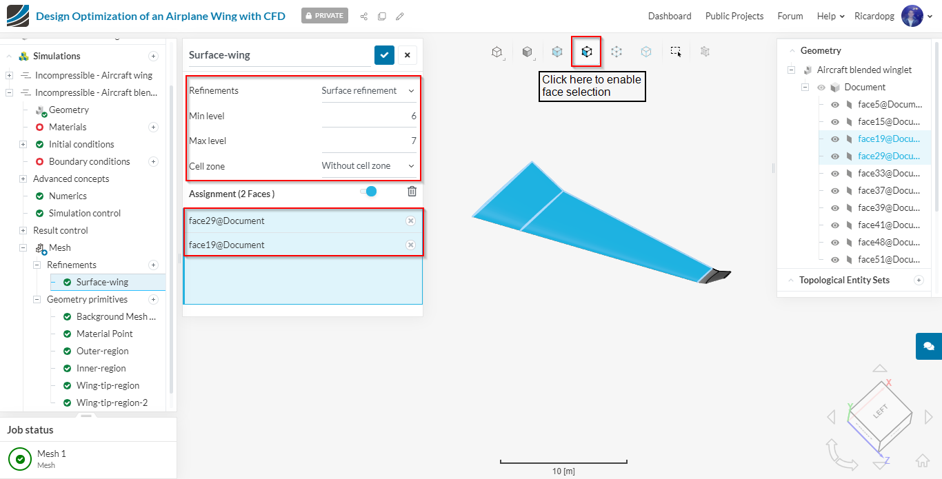
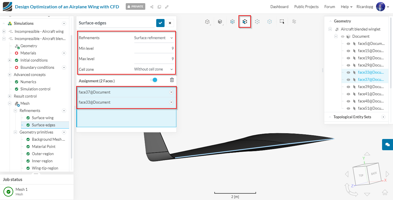
Surface-edges: this refinement will be used to refine the small surfaces of the wing.
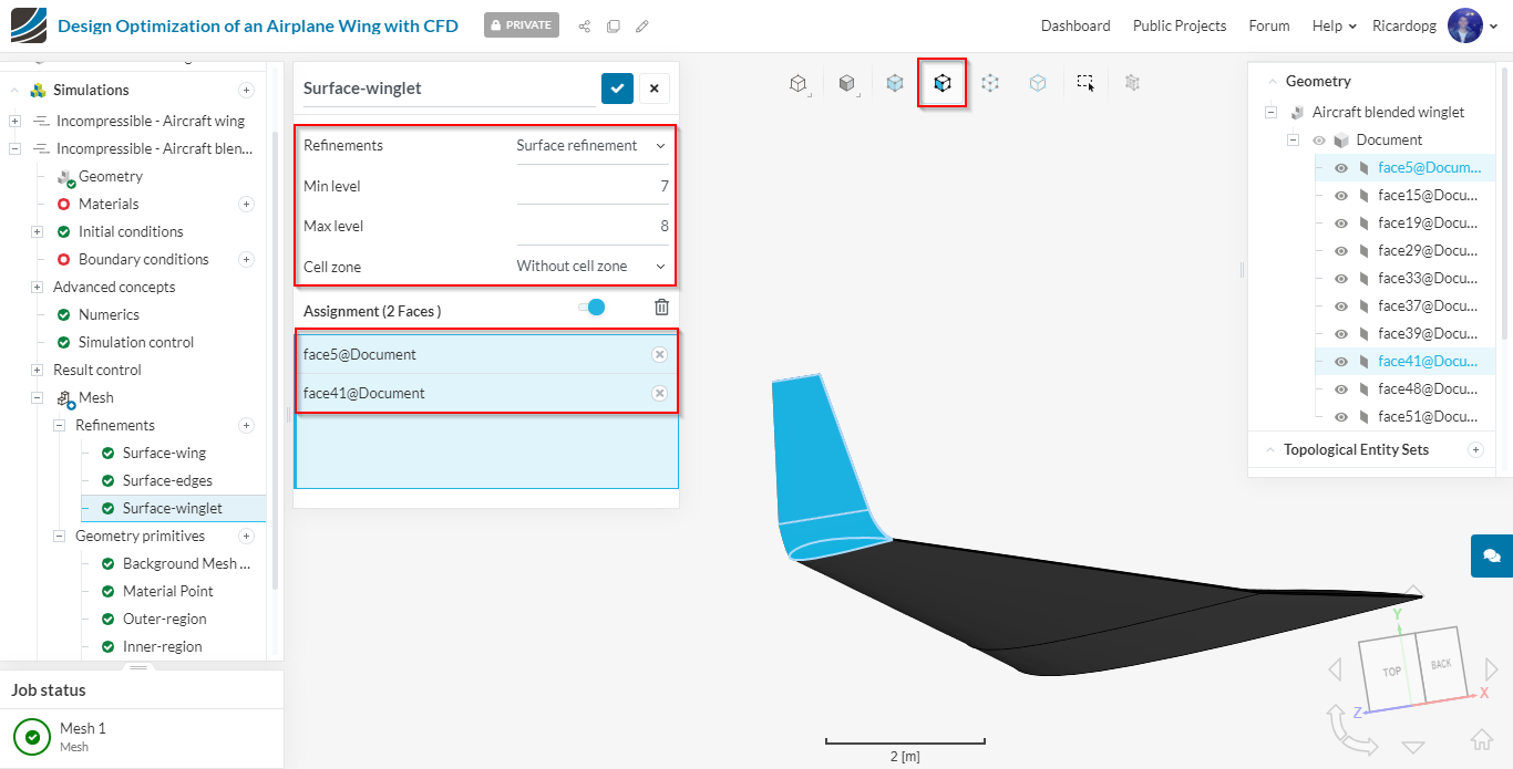
Surface-winglet: this refinement will be used to refine the bigger surfaces of the winglet.
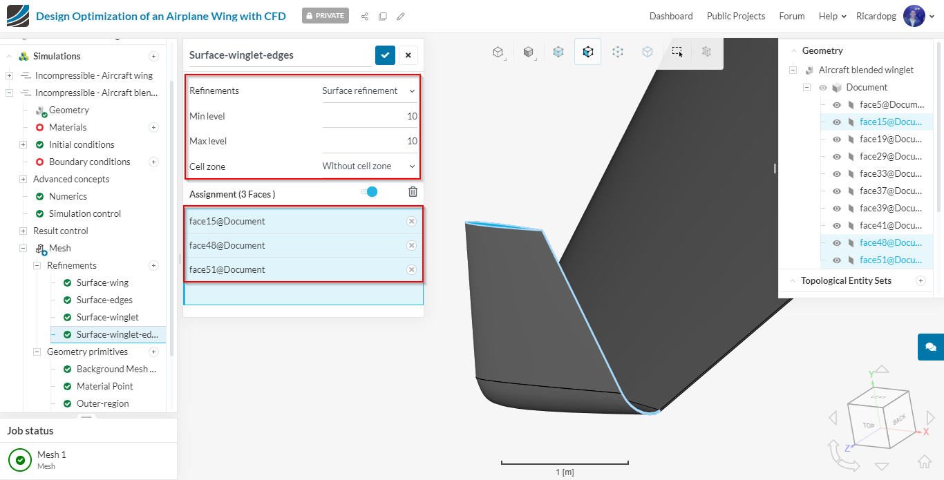
Surface-winglet-edges: this refinement will be used to refine the small surfaces of the winglet.
Region refinements: these refinements will refine the volume mesh. They are the same as the ones previously created for the geometry without a winglet.
Outer region
Wing-tip-inner-region
Wing-tip-region-2
Feature refinement: this refinement will refine the area near edges. This is important to capture sharp corners.
Inflate boundary layer: the layer refinement is important to capture the boundary layer near the wall. This will create layer cells following the surface curvature near the walls.
The Inflate boundary layer refinement is the same one from the previous geometry:
Please head over to the advanced mesh settings and adjust the parameters with the same inputs from the first mesh.
That’s all. Remember to save the changes before clicking on Generate.
Once done with both meshes, follow Session 1 - Part-II for the Simulation Setup.