Aerospace Workshop 2 Session-1 Homework
Recording

Homework submission
Submitting all three homework assignments will qualify you for a free Professional Training (value of 500€) as well as a certificate of participation.
Homework 1 - Deadline Date 09/29 at 12pm
Exercise
The task is to optimize an aircraft wing with and without winglet. The two geometries are as shown below.
For these cases we will use the “Hex-Dominant Parametric” meshing operation which provides full functionality to mesh complex geometries. The Tutorial below will provide detailed steps on how to use each meshing feature to get a well resolved mesh.
Step-by-Step
Import the project by clicking the link below. ( Crtl + Click to open in a new tab )
Click to Import the Homework Project
Once the project is imported, the workbench is automatically opened. Then follow the steps below for setting up an incompressible flow simulation.
Mesh-1 (Aircraft wings)
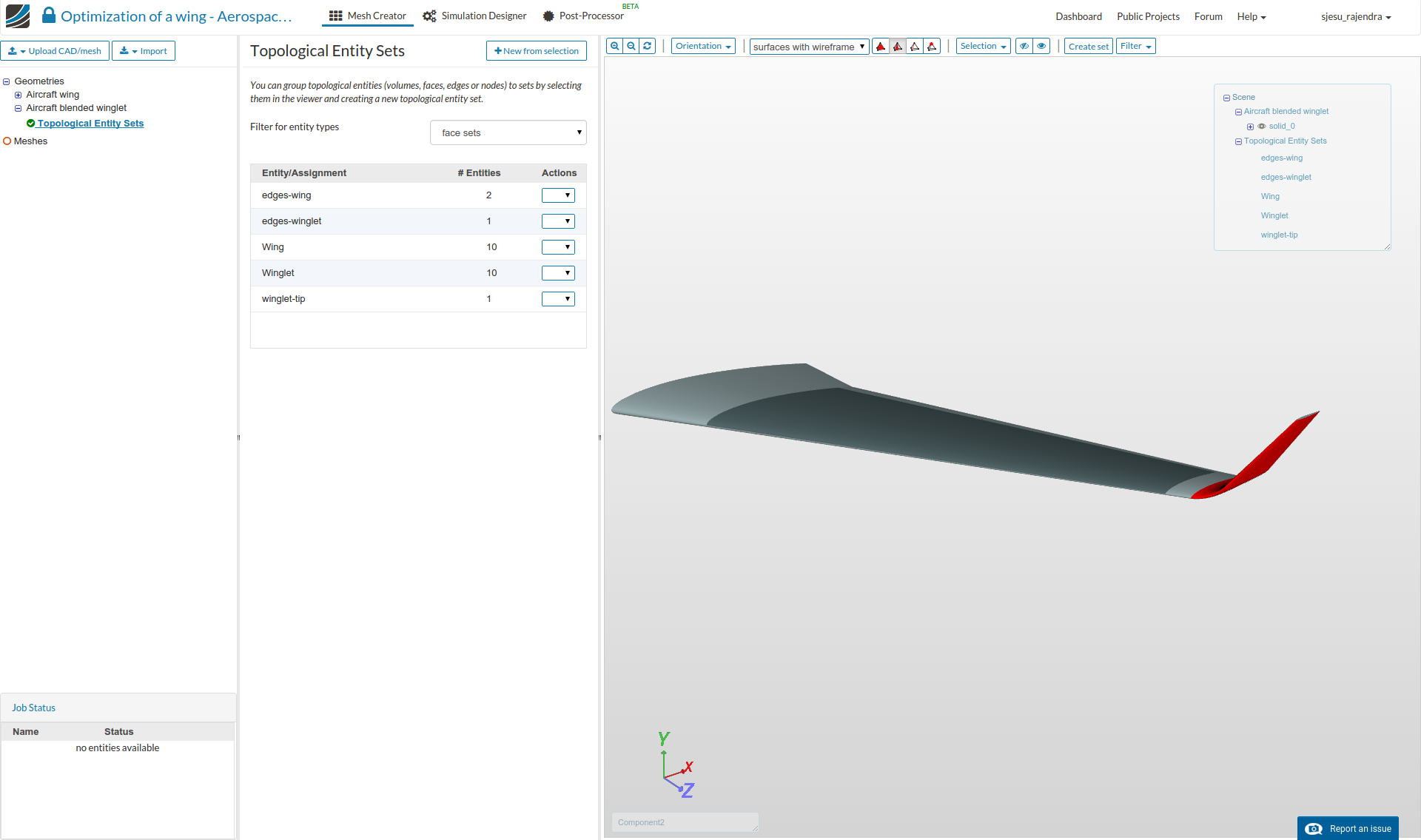
Geometry
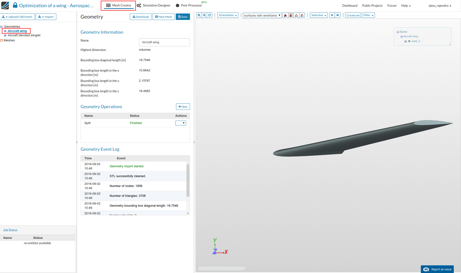
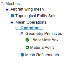
Note: The imported geometry has pre-created ‘Topological sets’ for some essential geometry faces. These sets will be later used for mesh refinements.
The created Sets are shown in the figure below, you can click to highlight the set in red.
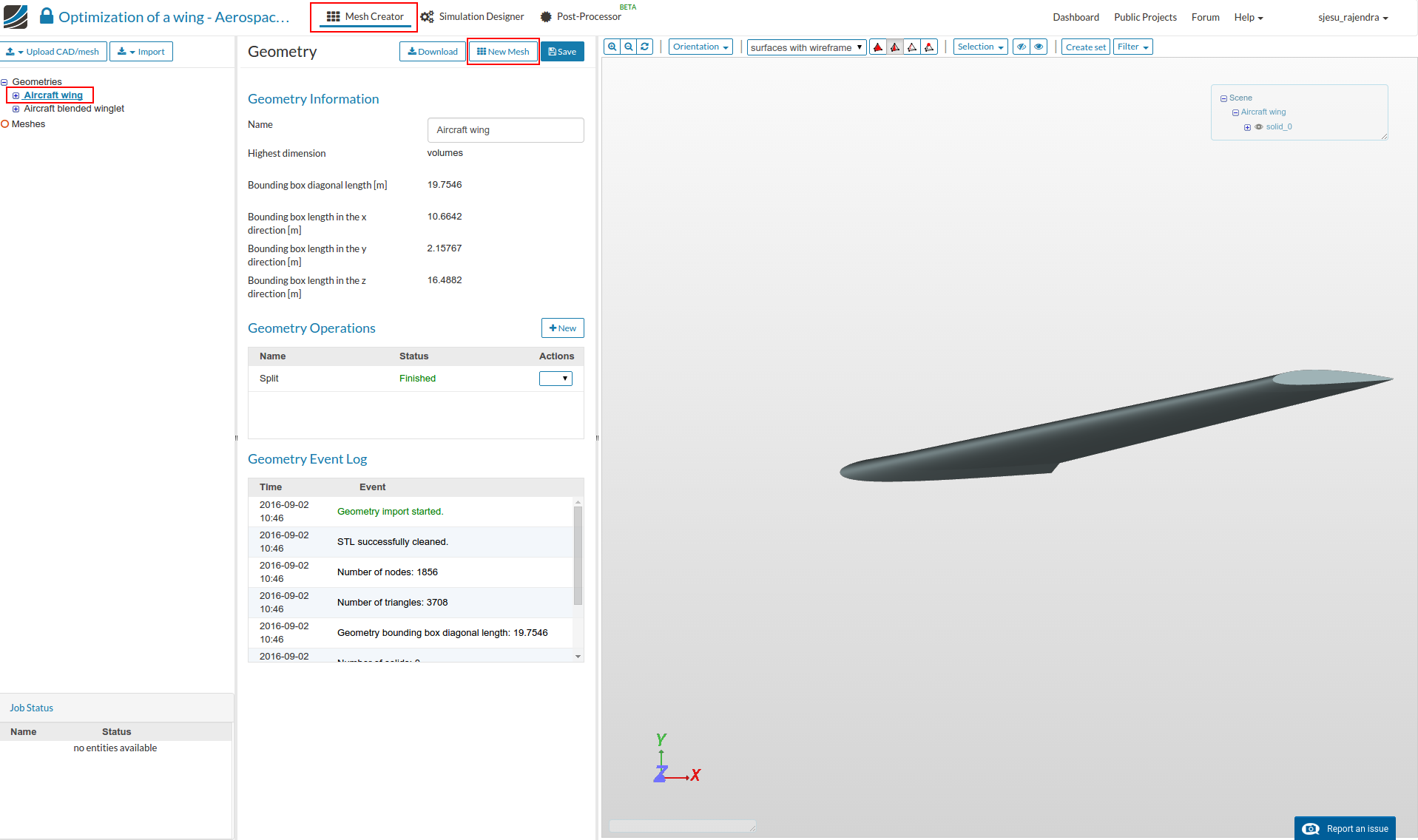
Creating a Mesh
- Select the geometry and click on ‘New Mesh’ button to create a new mesh operation as shown.
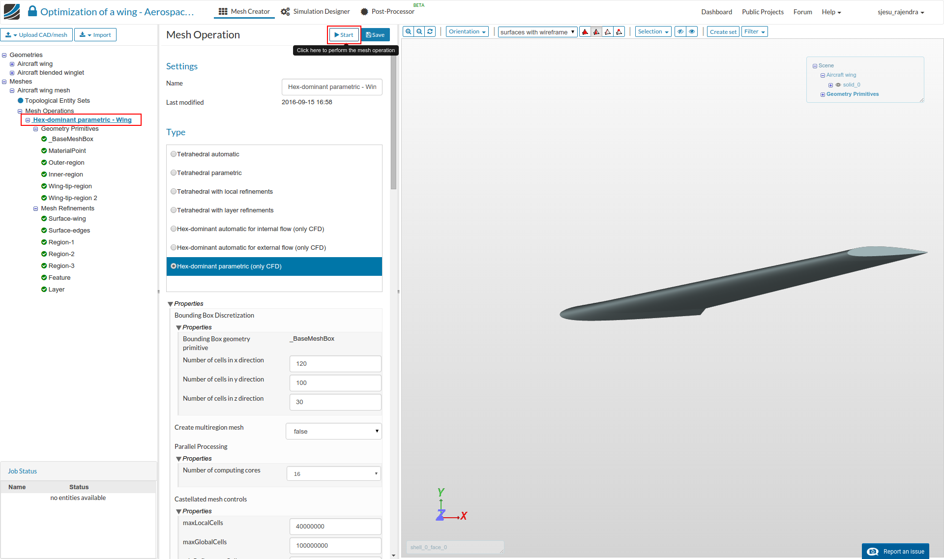
Main Settings
- In the Main Settings , select “Hex-Dominant Parametric (only CFD)” . Then specify the following parameters and click the Save button.
Number of cells in X-direction: 120
Number of cells in Y-direction: 100
Number of cells in Z-direction: 30
Number of computing processors: 16 ( Please note this has been updated 29-09-16 to avoid errors )
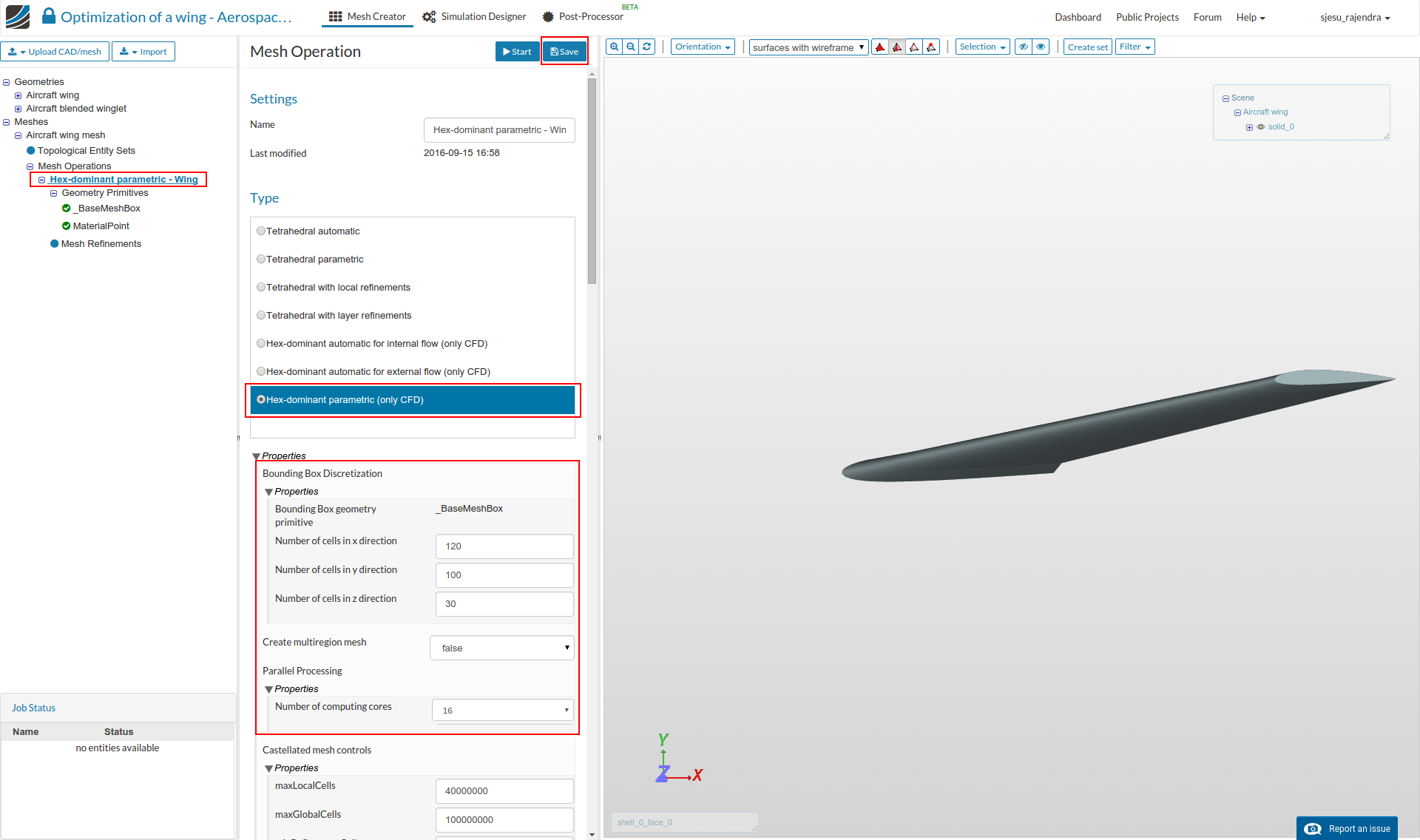
- After saving the tree is extend with 2 new entries, called ‘BaseMeshBox’ and ‘Material Point’ which must be defined.
Geometry Primitives
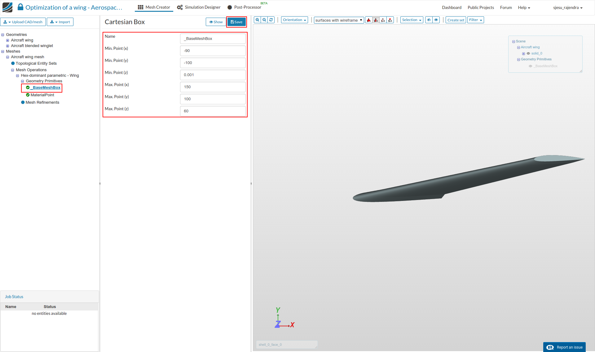
Base Mesh Box
The ‘Base Mesh Box’ defines the outer flow domain boundaries. This must be significantly larger for external flow. Enter the values as shown and click Save.
Min X= -90
Min Y= -100
Min Z= 0.001
Max X= 150
Max Y= 100
max Z= 60
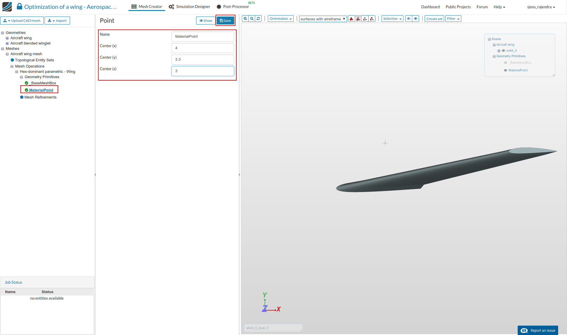
Material Point
The ‘Material Point’ specifies the region that will be meshed. So in this case the point must be out side the aircraft body.
Enter the values as shown and click Save.
Center X= 4
Center Y= 3.3
Center Z= 3
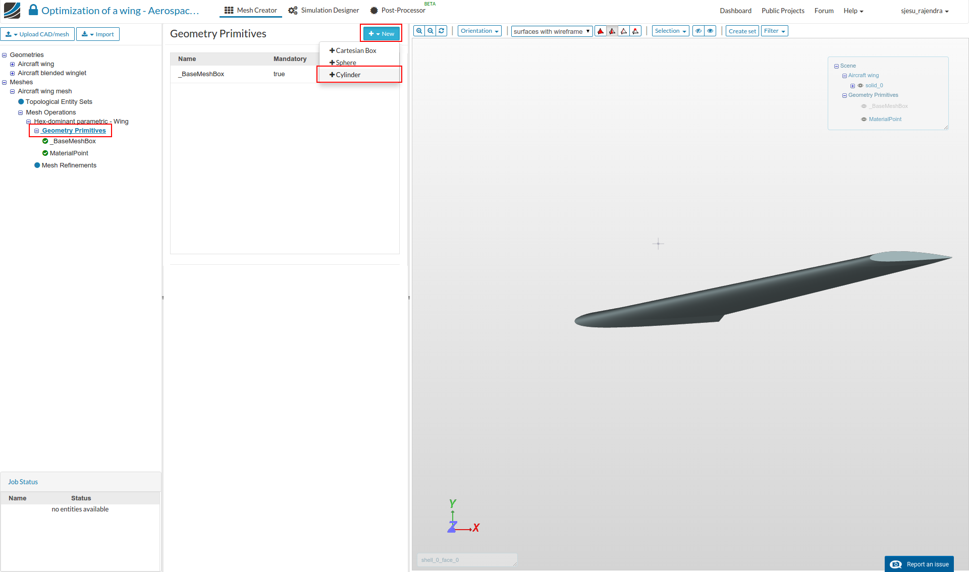
Further primitives
- We will create 4 entities that will be used for mesh region refinements later in the meshing setup.
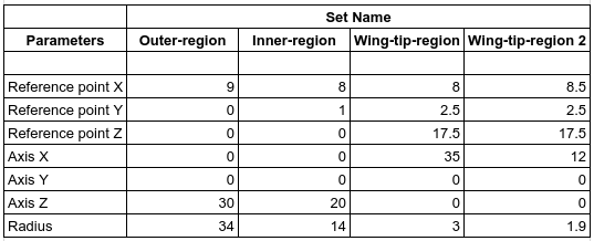
- To create a New entity, click on ‘Geometry Primitives’ and then the ‘New’ button on top to select a ‘Cylinder’ entity.
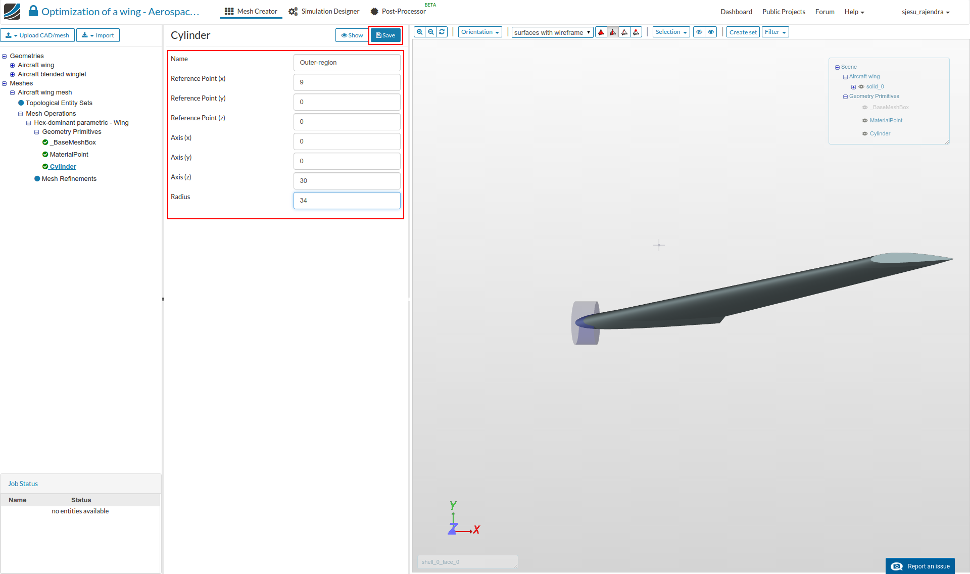
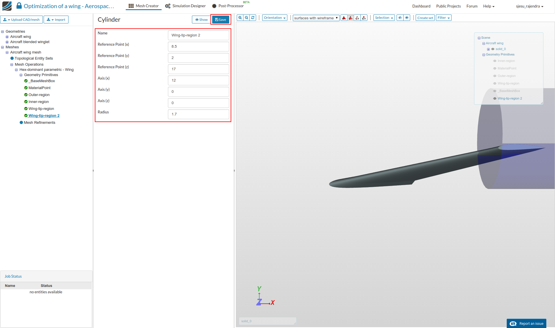
The table details the parameters for the 4 cylinder entities that are shown in the figures below.
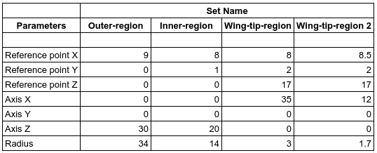
.
Outer-region
Inner-region

Wing-tip-region
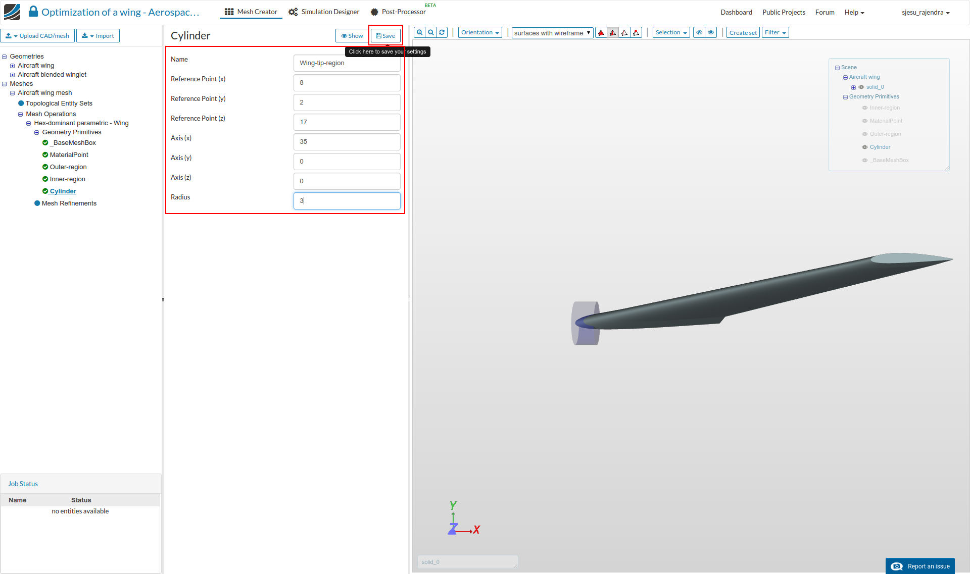
Wing-tip-region 2
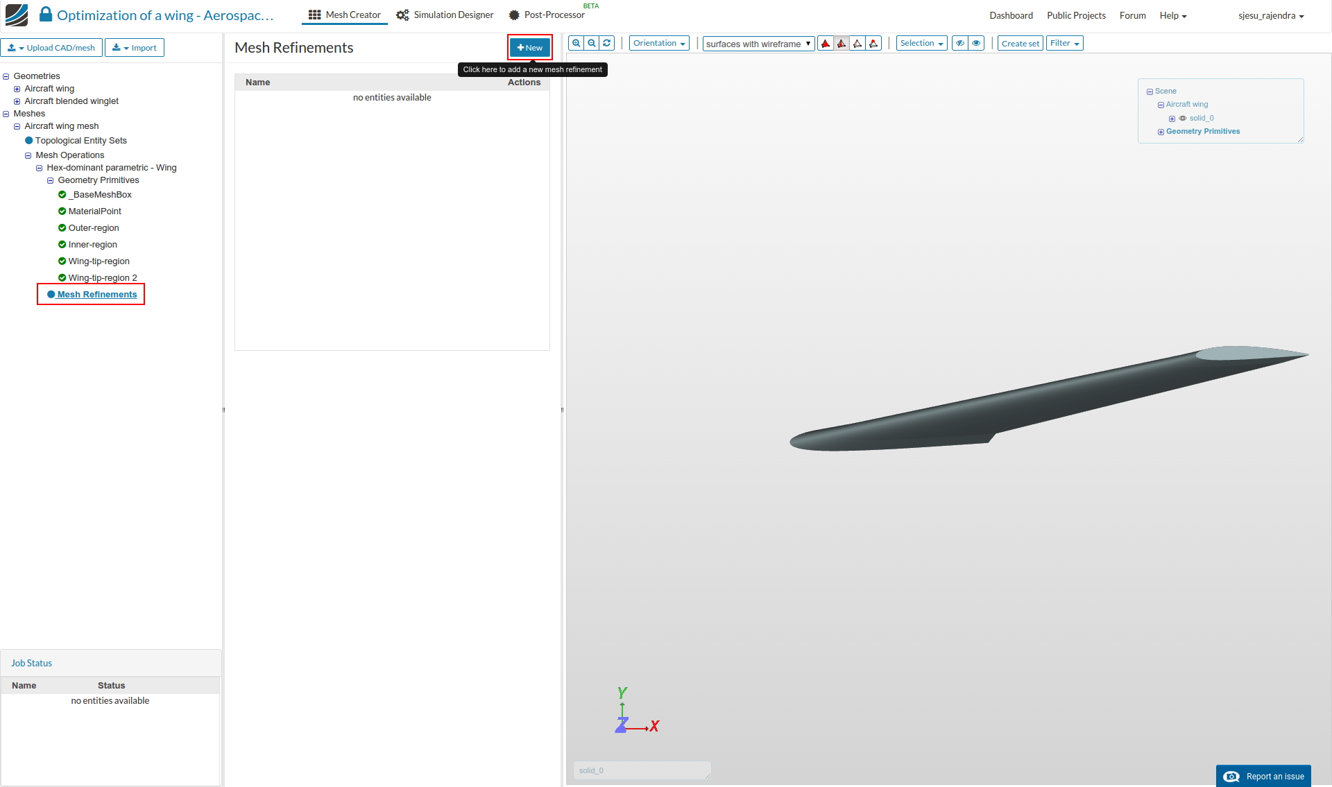
Mesh Refinements
We will now add the necessary mesh refinements for the previously created geometry sets and the geometry primitives.
- Click on ‘Mesh Refinements’ and click ‘New’ button to add a refinement.
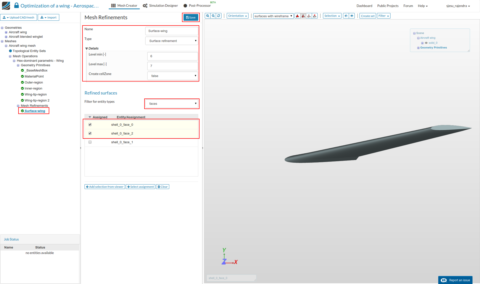
Surface refinements
- This refinement will used to refine the bigger surfaces of the wing.
Select the settings as follows and click Save.
Name: Surface-wing
Type : Surface refinement
Level Min : 6
Level Max : 7
Assigned entity Type: Faces
Name: ‘shell_0_face_0’, ‘shell_0_face_2’
.
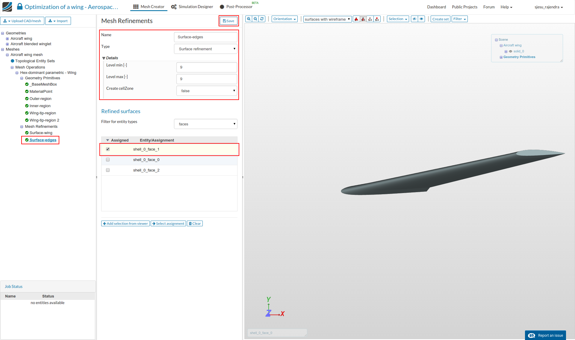
- This refinement will used to refine the small surface of the wing.
Select the settings as follows and click Save.
Name: Surface-edges
Type : Surface refinement
Level Min : 9
Level Max : 9
Assigned entity Type: Faces
Name: ‘shell_0_face_1’
.
Region refinements
These refinements will refine the volume mesh. We will create 3 region refinements and assign them the previously created geometry primitives.
- So create a new ‘Mesh Refinement’ .
- and enter the settings as follows:Wing-tip-region****Wing-tip-region
Name: Region - 1
Type : Region refinement
Mode : Inside
Distance : 1
Level : 2
Assigned geometry primitives: Outer-region

.
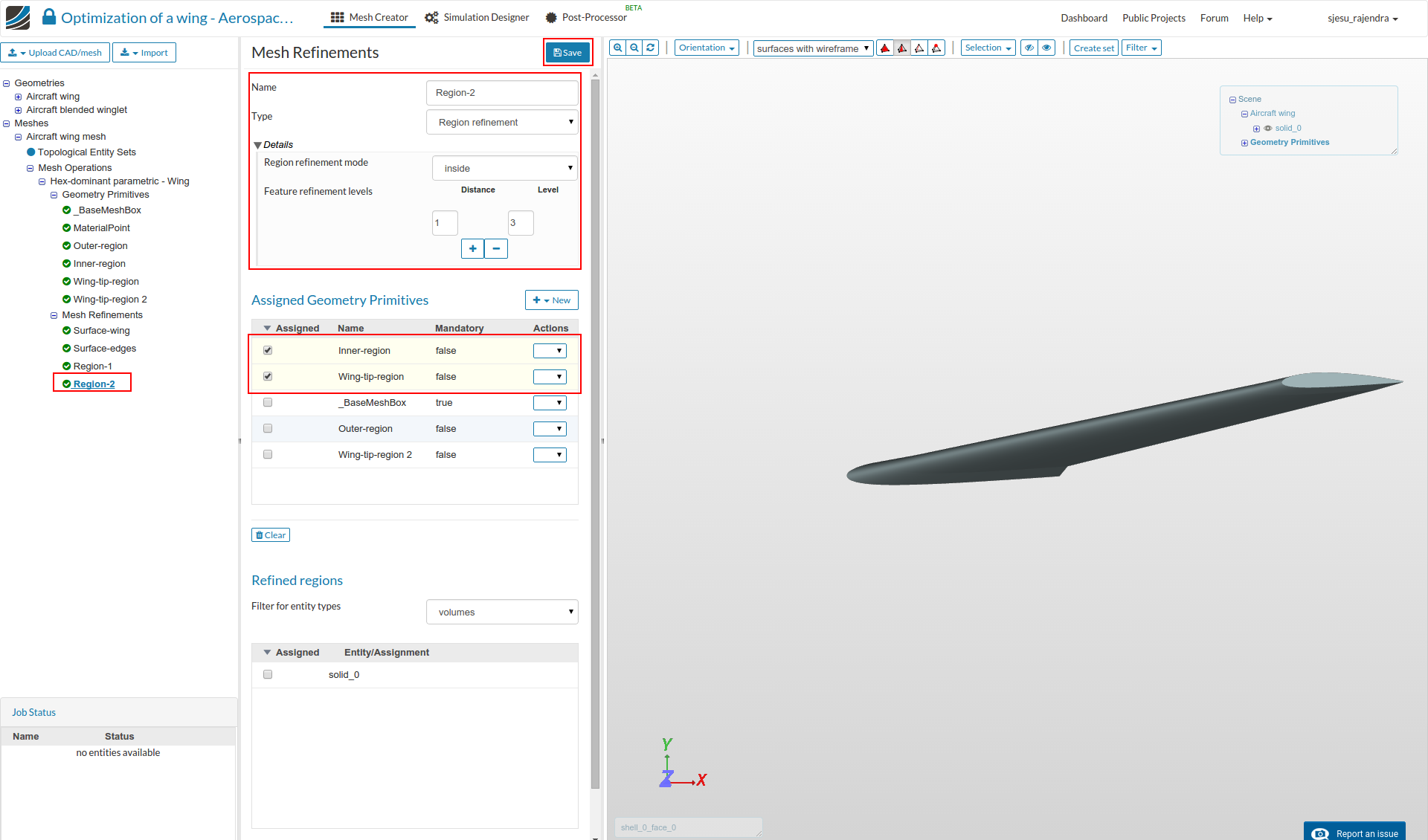
Name: Region - 2
Type : Region refinement
Mode : Inside
Distance : 1
Level : 3
Assigned geometry primitives: Inner-region, Wing-tip-region
.
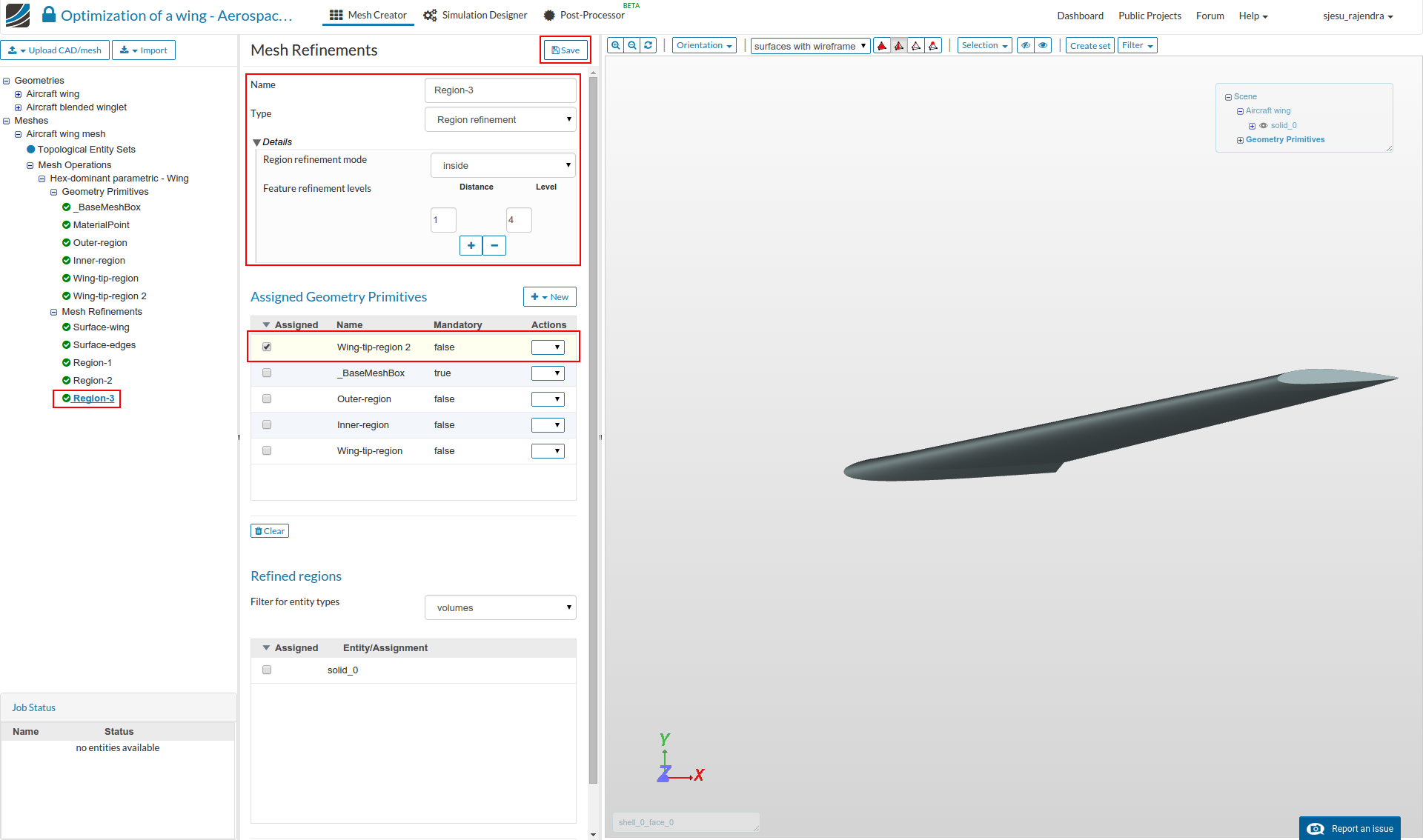
Name: Region - 3
Type : Region refinement
Mode : Inside
Distance : 1
Level : 4
Assigned geometry primitives: Wing-tip-region 2
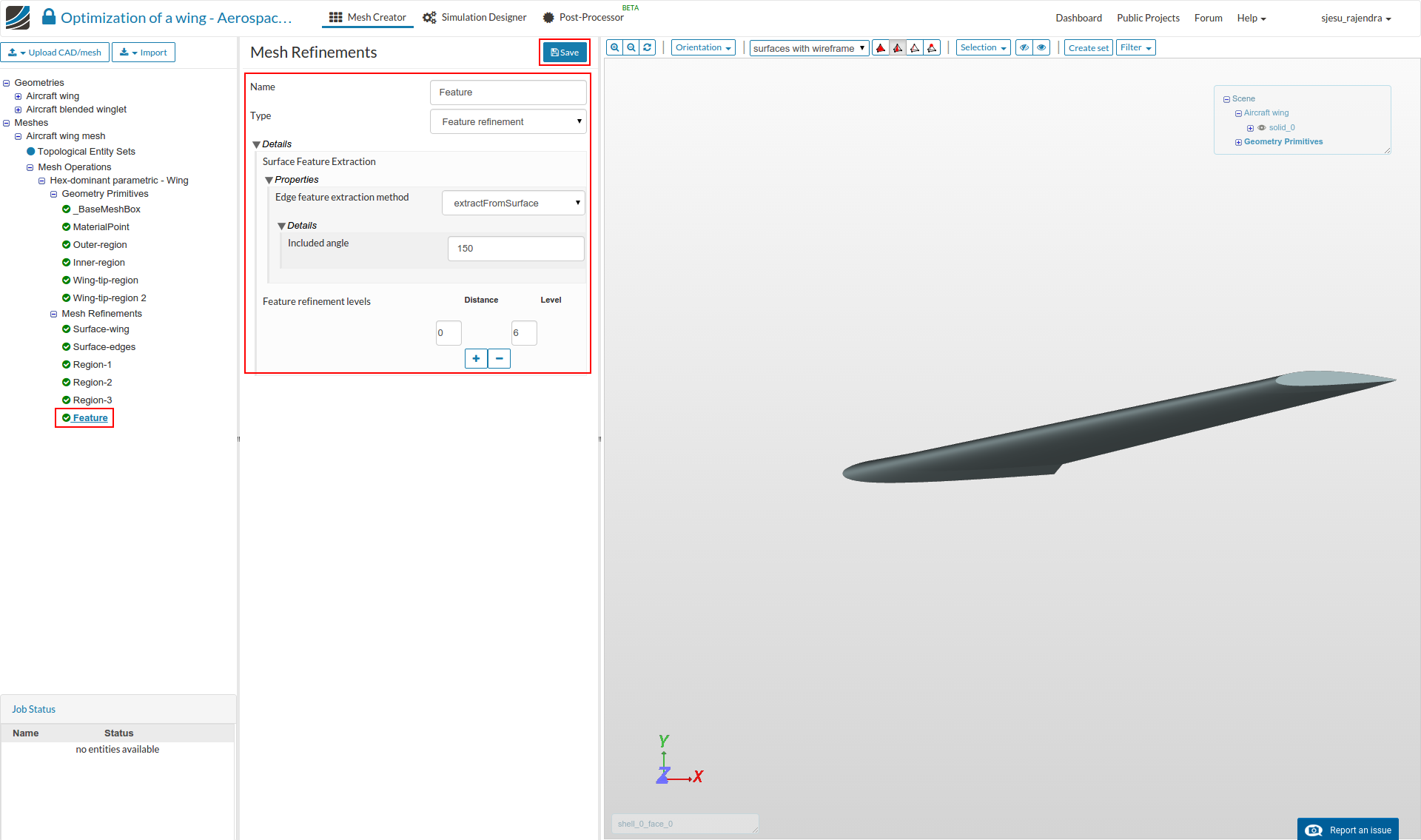
Feature refinement
The feature refinement will refine near edges. This is important to capture sharp corners.
- So Add a New ‘Mesh Refinement’, and choose Type as ‘Feature Refinement’. Give a Distance of 0 and a Level of 6.
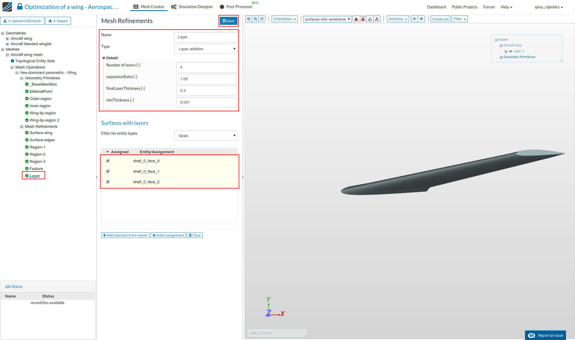
Layer refinement
The layer refinement is important to capture the boundary layer near the wall. This will create layer cells following the surface curvature near the walls.
- So Add a New ‘Mesh Refinement’, and choose Type as ‘Layer addition’. Change ‘Number of layers’ to 4, ‘expansionRatio’ to 1.65 and ‘minThickness’ to 0.001
- Then select all the surfaces ‘shell_0_face_0’, ‘shell_0_face_1’ and ‘shell_0_face_2’, and click Save.
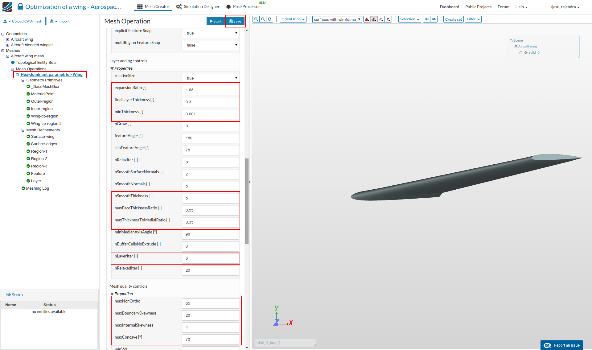
Some Advance settings
Lastly, we will change a few parameters in the Advance Settings by clicking on the mesh operation and scrolling in the settings panel as shown in figures below. This will help to get a good quality mesh for a complex geometry and get the appropriate y-plus value for the cases.
- Only the highlighted parameters need to be changed to the shown value.
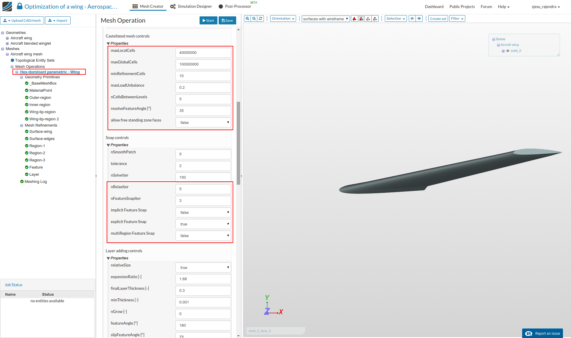
Finally, click Save.
Start the Meshing Operation
To Start the mesh operation click on the Start button at the top.
Please Note: Parallel compute cores are changed to 16 to avoid errors
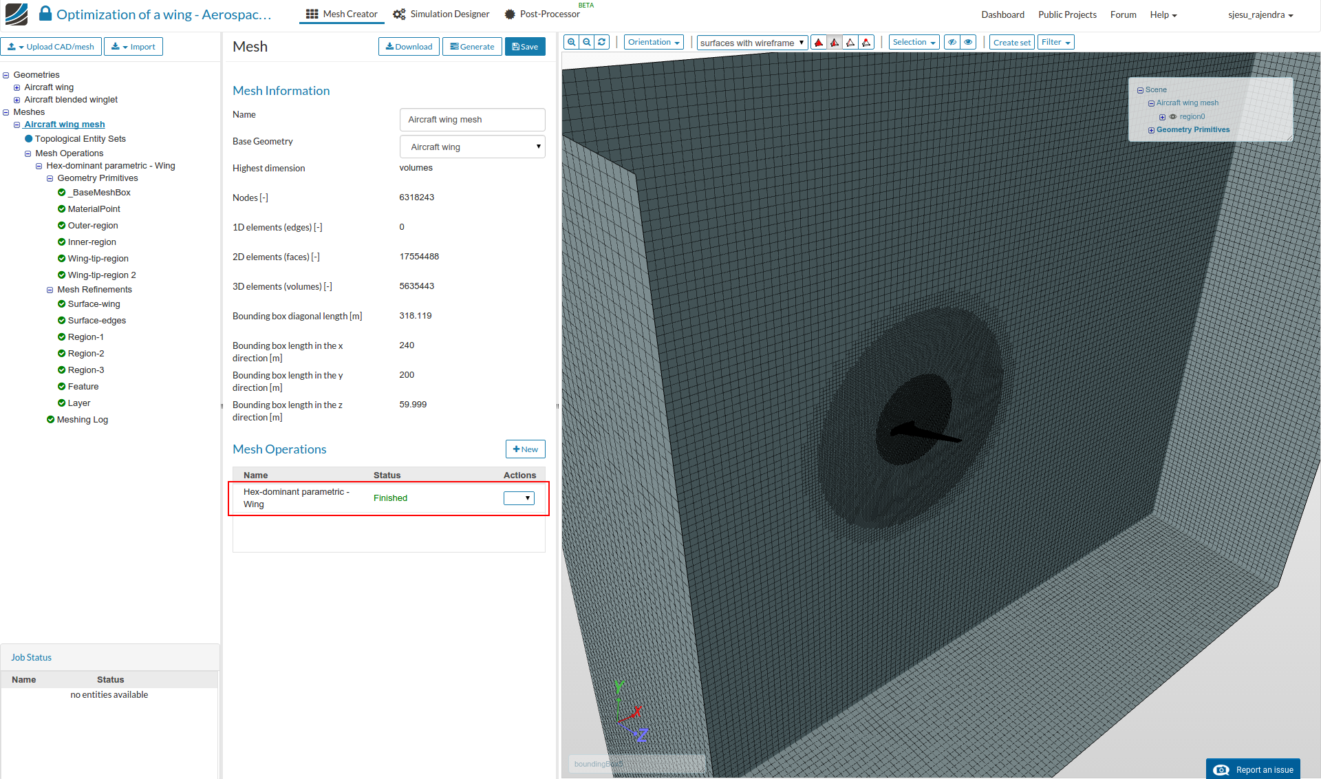
- The completed mesh looks as follows.
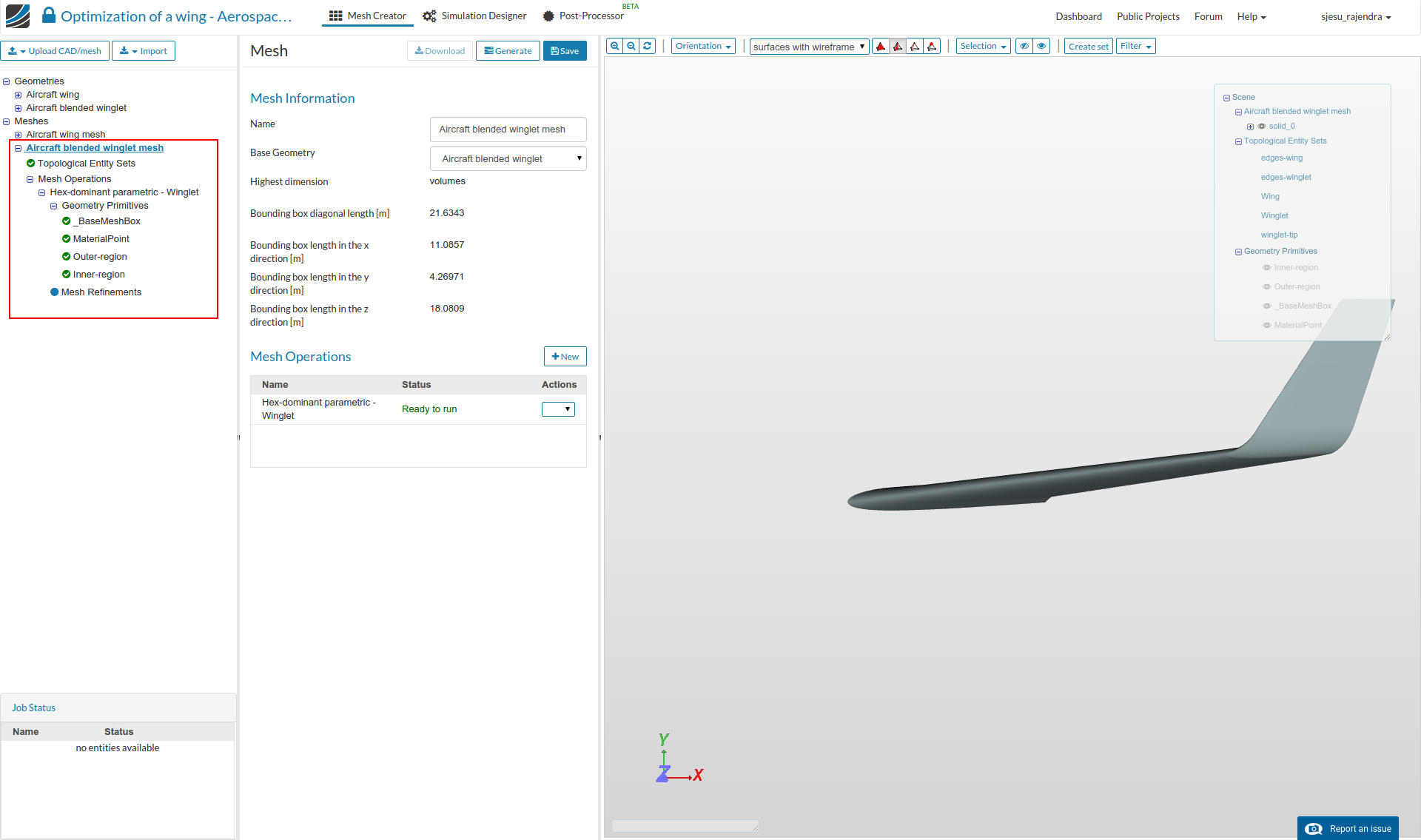
Mesh-2 (Aircraft - blended winglet)
- For the second mesh, please follow the same procedures as the previous case till the creation of ‘Geometry primitives’. In this the geometry Aircraft blended winglet geometry is selected to create the mesh. The viewer should look as shown below.
The table details the parameters for the 4 cylinder entities that are shown in the figures below.
Note that the change is only in geometry primitives Wing-tip-region and Wing-tip-region 2
Wing-tip-region
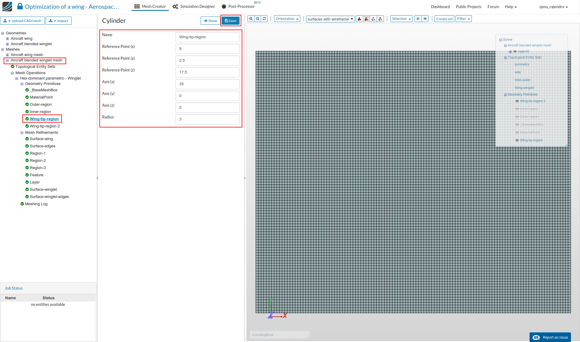
Wing-tip-region 2
Mesh refinements
The mesh refinements are to be done as follows.
Surface-wing
Select the settings as follows and click Save.
Name: Surface-wing
Type : Surface refinement
Level Min : 6
Level Max : 7
Assigned entity Type: Face sets
Name: ‘Wing’

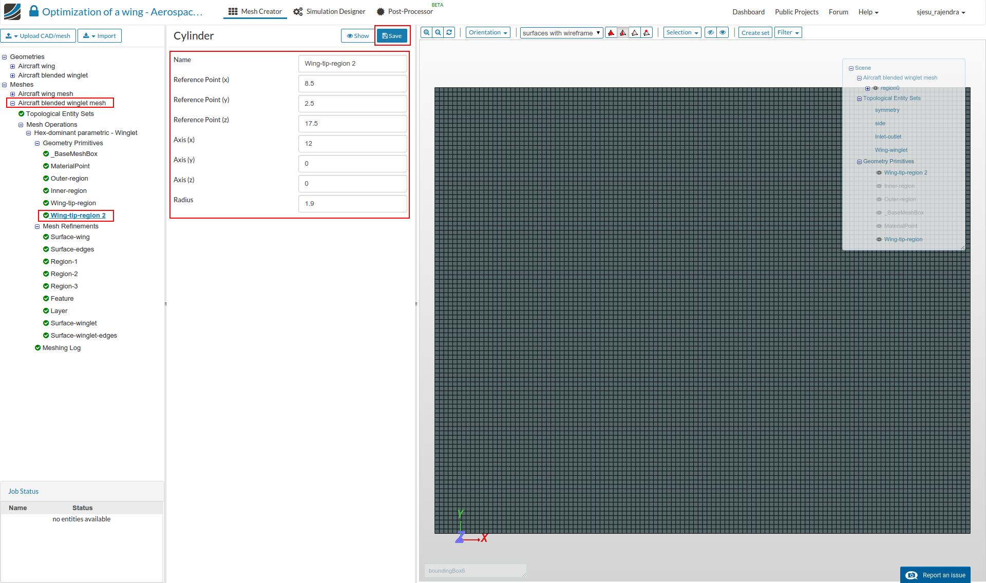
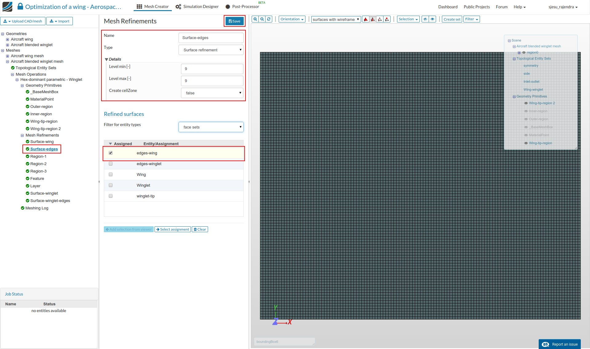
Surface-edges
Select the settings as follows and click Save.
Name: Surface-edges
Type : Surface refinement
Level Min : 9
Level Max : 9
Assigned entity Type: Face sets
Name: ‘edges-wing’
- The region refinements are same as the previous mesh. Please define the 3 regions as for the wing case.
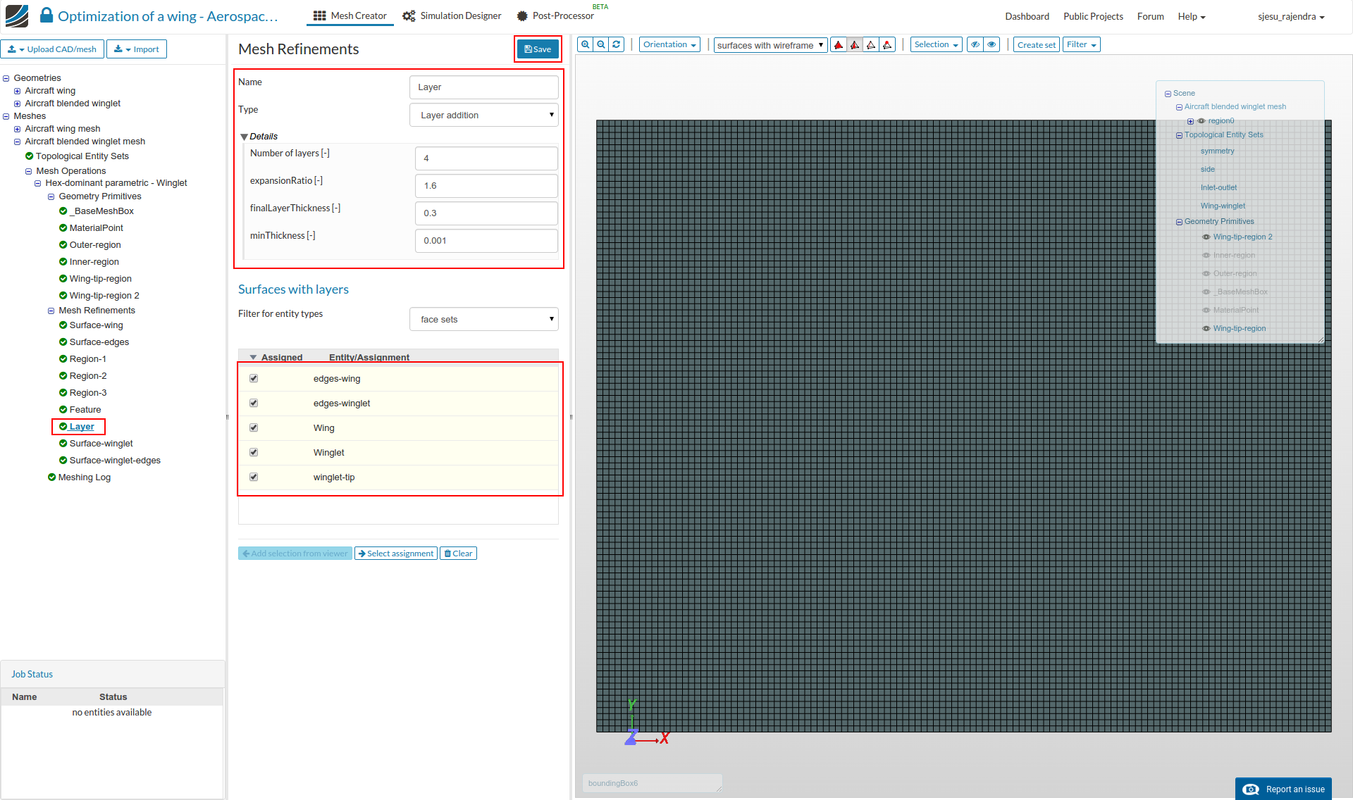
Layer
- Add a New ‘Mesh Refinement’, and choose Type as ‘Layer Refinement’. Change ‘Number of layers’ to 4, ‘expansionRatio’ to 1.65 and ‘minThickness’ to 0.001
- Then select all the face sets and click Save.
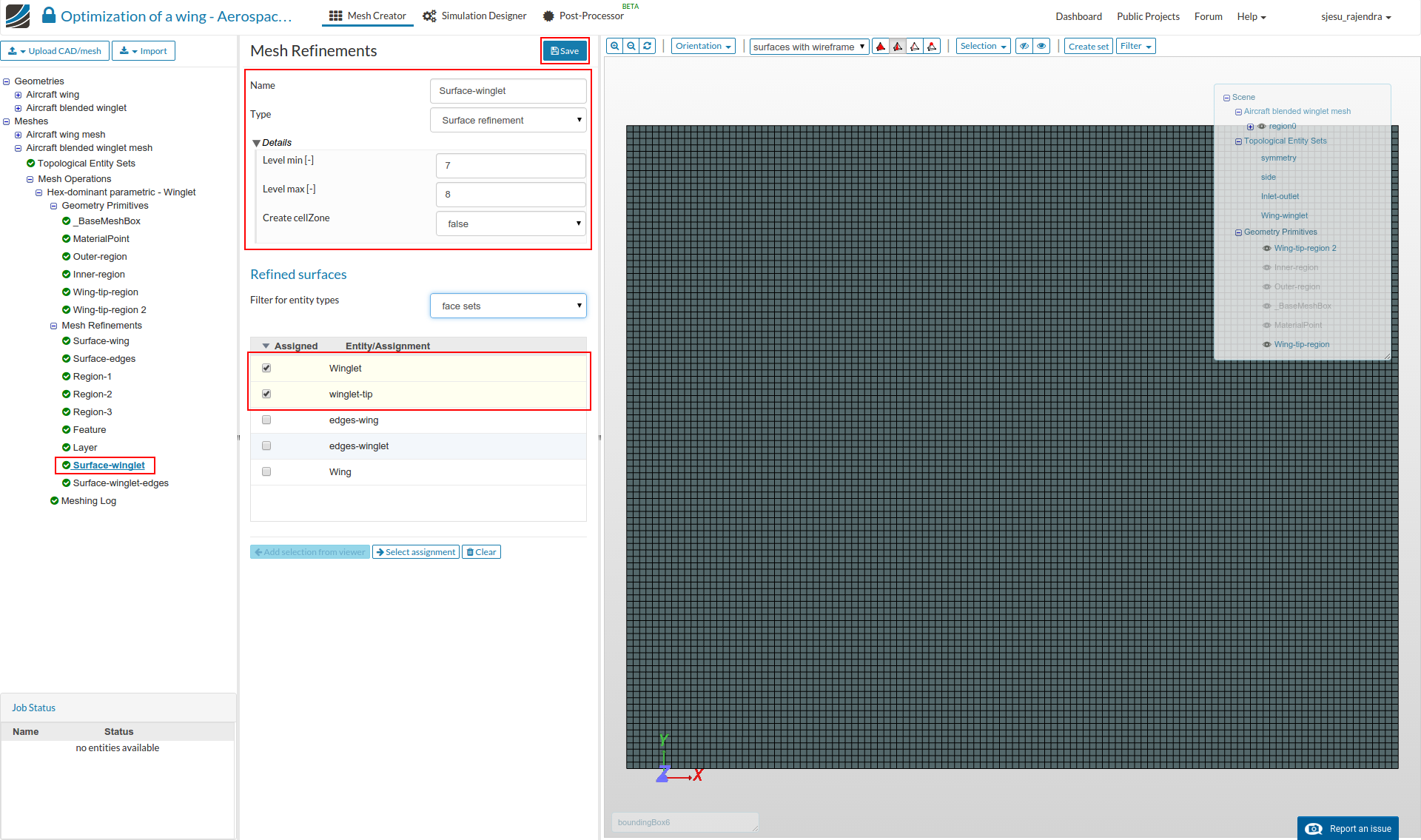
Surface-winglet
Select the settings as follows and click Save.
Name: Surface-winglet
Type : Surface refinement
Level Min : 7
Level Max : 8
Assigned entity Type: Face sets
Name: ‘Winglet’ and ‘winglet-tip’
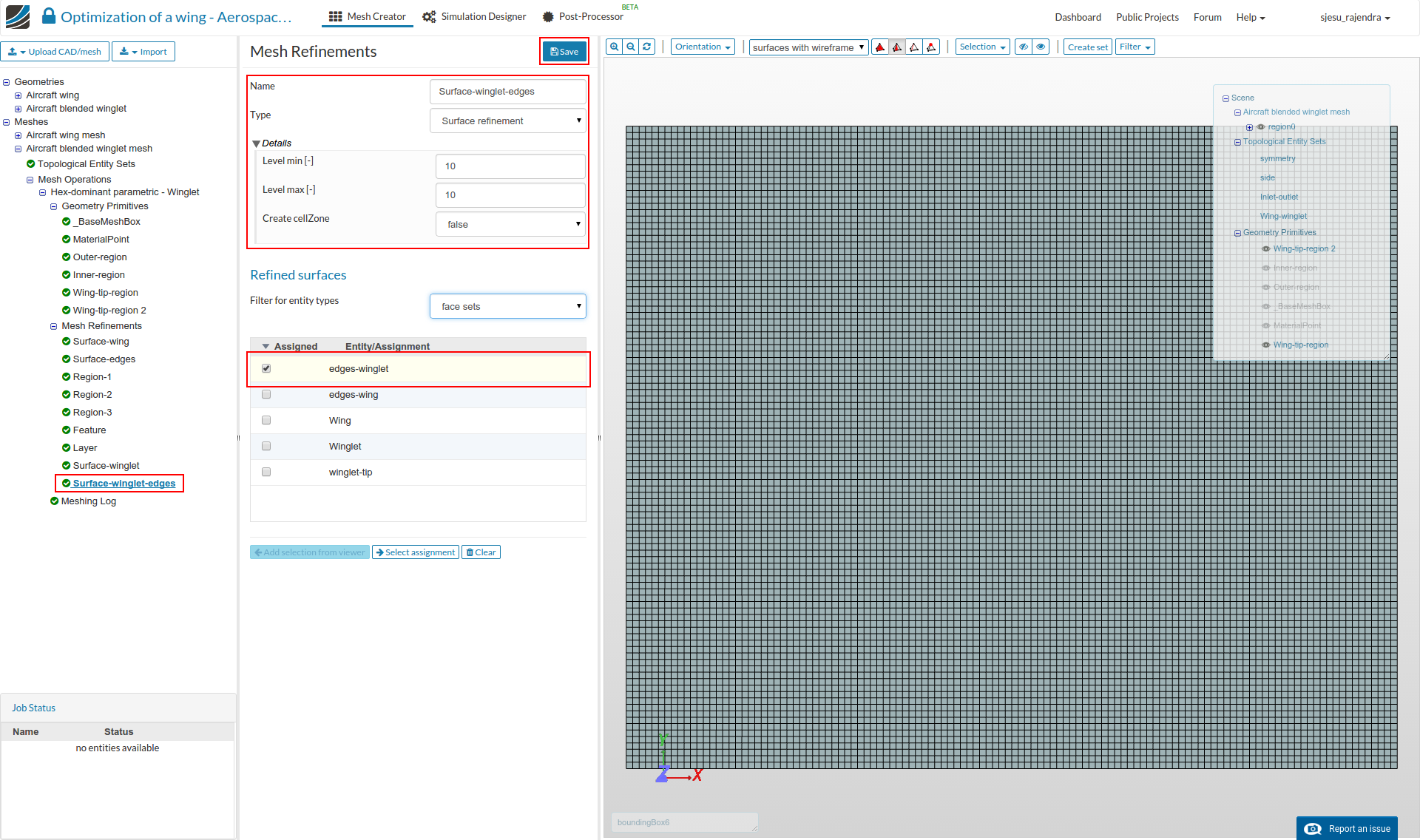
Surface-winglet-edges
Select the settings as follows and click Save.
Name: Surface-winglet-edges
Type : Surface refinement
Level Min : 10
Level Max : 10
Assigned entity Type: Face sets
Name: ‘edges-winglet’
- That’s all. Once done click the ‘Start’ button to begin the meshing operation.
 None of my university lecturers in fluid dynamics couldn’t explain it so clearly.