I would like to precise few points, as vague ideas are counter productive and it is better to avoid them.
-
For MRF rotation direction, use ‘RIGHT HAND’ rule ‘RIGHT THUMB’ rule. When your thumb points in Axis direction, other fingers show rotation direction. (Assuming your specify positive rotation speed: see rule 4).
-
If MRF zone is rotating on any ‘plane’, like XY, YZ, XZ, your axis can be just vertical line normal to that plane.
-
Axis can be ve+ or ve-, it will impact rotation direction, following rule1. They do not need to be normalized to 1.
-
Rotation direction can be changed as well by defining positive or negative rotation speed in radians.
-
If your MRF zone is ‘tilted’ you need to use rotation origin an axis definition. Calculation of correct axis of rotation cannot be done in SimScale in that case. You should use your CAD (and spacial imagination) to find how to define correct axis of rotation (it could be elaborated further, if necessary).
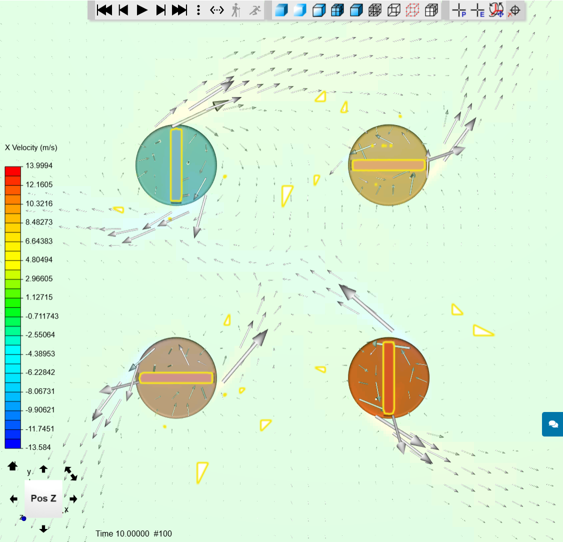
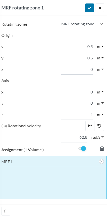
Below is a simple example of 4 MRF zones, being barre mixers in a pool. All have 62.8 rad/sec rotation speed, three have Z+ rotation axis and rotate anti clockwise. One (left top) has Z- rotation axis defined, hence it rotates clockwise. Distance among mixers is 1 m. Center of pool is X, Y; 0, 0.
Let’s look into the pool from the top:
First MRF definition is here, other definition will have different origin, but Z+ (1 m instead of -1 m).
Perhaps it is enough for the moment.
Cheers,
Retsam