@Retsam ,
I am currently running a similation on Savonius Wind Turbine and I am stuck at setting this. Can anyone tell me what to input for this section please?
@Retsam ,
I think you are close with (0,0.5,0) for the axis in the current parameters for the sim (EDIT: the runs you did were wrong at (0,0,1), but perhaps the vector magnitude of the Axis needs to be normalized to 1 , like the directions in the directions for the Coefficients results need to be (that is a little known fact in itself  )… (ie 0,1,0 and not 0,0.5,0) … in any case, I would use (0,1,0) because I am so used to normalizing the vector magnitude value for directions
As far as Origin, I did not download and look at CAD file but I assume that the rotation axis in the CAD file runs through (0,0,0)…
Lets wait and see what MRF master @Retsam has to say…
@tedmund , see my edited post above, your runs that had (0,0,1) for axis were wrong…
And of course ‘Rotation velocity’ should have its ‘sign’ set to right hand rule on (0,1,0).
I can never remember if that direction is with respect to the desired rotation of the geometry or of the air in the MRF, you can probably research that and post back here, or someone else can answer my query concerning direction…
You mean the rotational velocity should be negative?
Yes it is possible!
After you get the answer to my query, if axis (0,1,0) ends up needing a -ve rotational velocity and you just can’t wrap your brain around that, then put axis to (0,-1,0) and set rotational velocity to +ve
This is a common issue and the User interface and help text boxes should be MUCH BETTER ( @jousefm and @anon35156959 )
I think the rotational velocity should be set with respect to the desire rotational motion of the wind turbine
If you are SURE, then do it…
Therefore, a negative is needed for clockwise rotation!
Sir, thank you so much for spending time on solving my doubts! I really appreciate your effort!
I would like to precise few points, as vague ideas are counter productive and it is better to avoid them.
For MRF rotation direction, use ‘RIGHT HAND’ rule ‘RIGHT THUMB’ rule. When your thumb points in Axis direction, other fingers show rotation direction. (Assuming your specify positive rotation speed: see rule 4).
If MRF zone is rotating on any ‘plane’, like XY, YZ, XZ, your axis can be just vertical line normal to that plane.
Axis can be ve+ or ve-, it will impact rotation direction, following rule1. They do not need to be normalized to 1.
Rotation direction can be changed as well by defining positive or negative rotation speed in radians.
If your MRF zone is ‘tilted’ you need to use rotation origin an axis definition. Calculation of correct axis of rotation cannot be done in SimScale in that case. You should use your CAD (and spacial imagination) to find how to define correct axis of rotation (it could be elaborated further, if necessary).
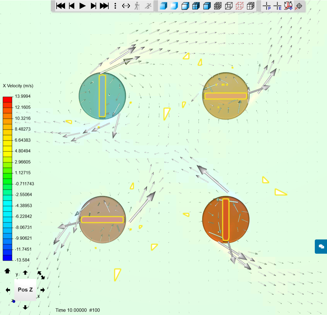
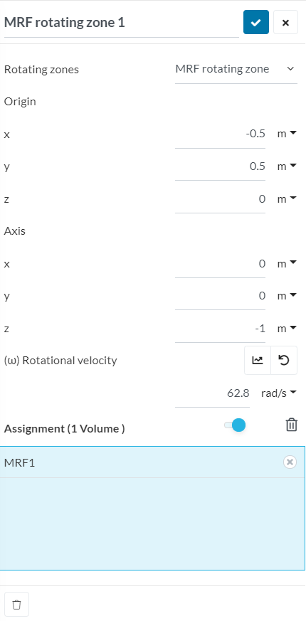
Below is a simple example of 4 MRF zones, being barre mixers in a pool. All have 62.8 rad/sec rotation speed, three have Z+ rotation axis and rotate anti clockwise. One (left top) has Z- rotation axis defined, hence it rotates clockwise. Distance among mixers is 1 m. Center of pool is X, Y; 0, 0.
Let’s look into the pool from the top:
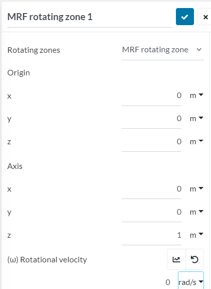
First MRF definition is here, other definition will have different origin, but Z+ (1 m instead of -1 m).
Perhaps it is enough for the moment.
Cheers,
Retsam
What about providing a special direct confirmation of whether the ‘rotation direction’:
OR
![]()
I cannot grasp you suggestions, Dale: would you be kind to elaborate, please?
Rotation direction of MRF zone is tied to axis of rotation… Hmm, may be I’m missing something… 
OK, first I do not know what a barrel pump impeller looks like, so I do not know what direction I would expect the water to rotate in the TopLeft pump image.
If the rotor geometry inside the MRF, rotates CW, would I expect the water to rotate CW ![]()
Are you saying that I cannot have a +Z axis of rotation and a -ve MRF direction ![]() (that may be my little brain issue here)
(that may be my little brain issue here)
Even if that were so, I still need to know if my CCW Right Hand fingers were pointing in the direction that the rotor would spin or in the direction that the water in the MRF would spin relative to the domain, wouldn’t I ![]() …
…
Well, I though I was clear, I’m ready to continue. Short answer to above question is you can have all combination of Z+, Z-, ve-, ve+, If you prefer to keep ve+, you change rotation direction by flipping axis.
I attached above picture you see FLUID rotating clockwise: it means your GEAR is rotating clockwise. So, your gear rotates in the MRF direction, your fingers point in that rotation as well.
YES, so your answer is #1 ![]() , I am better at visualizing axial flow fans
, I am better at visualizing axial flow fans ![]() , I think some centrifugal fans do weird things to my brain…
, I think some centrifugal fans do weird things to my brain…
The water in the MRF of an axial flow turbine would spin opposite to the direction of the propeller type impeller since, in the math of an MRF, is the geometry not assumed to stand still :question ![]() I guess, in the math, the fluid automatically rotates in the reverse direction of input (I need to keep my head out of the math
I guess, in the math, the fluid automatically rotates in the reverse direction of input (I need to keep my head out of the math ![]() )
)
I would rather say ‘flow’, not ‘rotate’ in that case: flow will be in Z+ or Z- direction following the twist of blades.
I take 3 days off due to travel and hope you will recover, Dale. ![]()
But the flow leaving behind a propeller has rotational momentum in the rotation direction of the prop (oops direction typo previously made, fixed now) due to viscous dragging along an arc on the chord, so in effect I see the wake as rotating outward too…
Have a good trip and at least I can’t bother you while you are away 

Ok sir, let me conclude what I understood, lets say for my case :
If my wind turbine is rotating in clockwise direction, then I should either input (0,-1,0) for the axia or have a negative value for the angular velocity? Is that what you are trying to say?
YES, I agree and that is my understanding!
And in my brain  , I see that if geometry rotates CW, on a -Y axis (0,-1,0), hence a down right hand thumb, and my right hand fingers AGREE with the geo rotation, then we need a +ve angular velocity, OR if geometry goes CW on a +Y axis (0,1,0), hence an up right hand thumb, and my my right hand fingers DISAGREE with the geo direction, then we need a -ve angular velocity, whew … I hope I did that right