Very thin boundary layers and y+ on complex geometry

Absolutely no problem! It is great that you communicate your feelings about the platform which helps us to further improve it and helps others in the end. So feel free to criticize as much as you can and let me know what we can do better! :+1:

@DaleKramer, I guess time for a hangout call if you are free in the next time to plan something great for our users here, what do you think? :slight_smile:

Cheers!

Jousef

@jousefm Yes, I am available most times, but my schedule changes a lot at the last minute, so we can try again :slight_smile:

1 Like

I understood that, which is why I was trying to suggest a way to get a larger cell count full model into SimScale than your 16 core limit can create. But that is likely moot now, read on…

If there was a way to recall settings from simulations (even failed ones) and mesh settings we would not have these problems like the current misplaced FLT ratio issue I saw. (I have asked for this - hint hint).

I copied your project and started my [own version here (I will delete this in a couple weeks)] [Deleted]

First, I am straying from my normal position that I don’t like to do the work myself for others, but here I will because you are making an effort and goals of this project are on my list to investigate anyway :wink:

Below are my changes to get a 5 layered mesh at 33 m/s (that is what your velocity vector approximated in magnitude). I tried to use all my previous suggestions to you as follows.

  1. I adjusted your 1m Level 0 grid to be square in all 3 axes by changing the mesh background box resolution.
  2. I determined a suitable reference length, turbulence parameters, layering parameters and FLT ratio as follows (I chose a y-plus of 165 to keep mesh small, fine tune later) EDIT: I just noted that originally I did the 1.3 ratio expansion to 6 layers instead of 5 (~fixed now). You get the idea tho I hope :slight_smile: :
  3. I deleted all your refinements and added just a surface refinement on all volumes to level 6-6 and an inflated boundary layer refinement for all surfaces using the above parameters.
  4. I ran the mesh with 16 cores in 24 minutes using 6.4 core hours, The resulting mesh was 4.3M cells. The layering stats show that the average layers per face is 4.9 and this is an average of 98% of a perfect 5 layers. Here is the first few lines of my layer stats spreadsheet, created by copying the table in the meshing log and resorting it:

    Here is a slice throught the horizontal and vertical stabs:

I will leave it to you to run a simulation and confirm the y-plus surface values.

I suggest not starting out with zero gradient walls (I have not had much luck with them but perhaps they behave better now). This gives you a baseline comparable for ‘Forces and Moments’ that can be used to see if zero gradient walls behave the same as slip walls at 0 Beta and 0 Alpha.

You can add further refinements as needed to stay within your 16 core limit (eventually I will have a procedure to optimize them too :wink: ). If you really want those small trailing edges to be layered, then you might try an (ugh) feature refinement and a further, finer surface refinement on those trailing edge surfaces.

Hope this gets you going again :slight_smile:

Dale

1 Like

@DaleKramer

I assume you’re referring to my Pressure Outlet walls with 0 Pa value. This is something I struggled with; how to keep the flow going in the specified direction. After testing a bunch of inlet-outlet and freestream conditions I settled on this method as the velocity vectors seem to stay constant after stabilization, at least as far as I have been able to introspect. However, I am seeing a strange issue that may be related - I’m using a velocity table to ramp velocity from 0 to 31 m/s over about 25s. The entire simulation time is 250s but over that time I still see a fairly dramatic difference in flow velocities between timesteps, such that I don’t necessarily trust that I’m dealing with fully developed flow by the end of the simulation. Any ideas on how better to implement flow? I initially wanted to move the model with straight on flow, but that doesn’t seem to be available in Incompressible.

1 Like

If you want to use zero gradient walls then we need input from others ( Power users ). I simply create a different geometry and mesh for each alpha or alpha/beta I want to investigate and used slip tunnel walls on an optimally sized BMB. I hope you are OK with finishing your mesh from here…

Thanks many times to you, @DaleKramer for your work on meshing and your direct help on this project. I was lost before and I didn’t know how much. Following the CFD master class, I naively expected that an incomplete boundary layer would simply change the magnitude of my results. In fact it completely changes the flow characteristics across a model, as I’ll show below. I was finding the results from my initial analysis really confusing and now I know why: I had a really crappy mesh with an overly-large boundary layer and poor coverage.

Side note: perhaps this is a trivial finding for you CFD experts out there, but for people like me (engineer with little experience in complex physics simulations), it’s super important. The accessibility of SimScale make it really tempting to throw something together and end up with a garbage-in/garbage-out result. I’ve seen more and more engineering candidates come through my door lately with an over-reliance on FEA/CFD methods and not enough skepticism or sophistication to even attempt corroborating the results with experiments or hand calcs. I’m hoping this post will serve as a warning for how wrong it can really be even if it looks right.

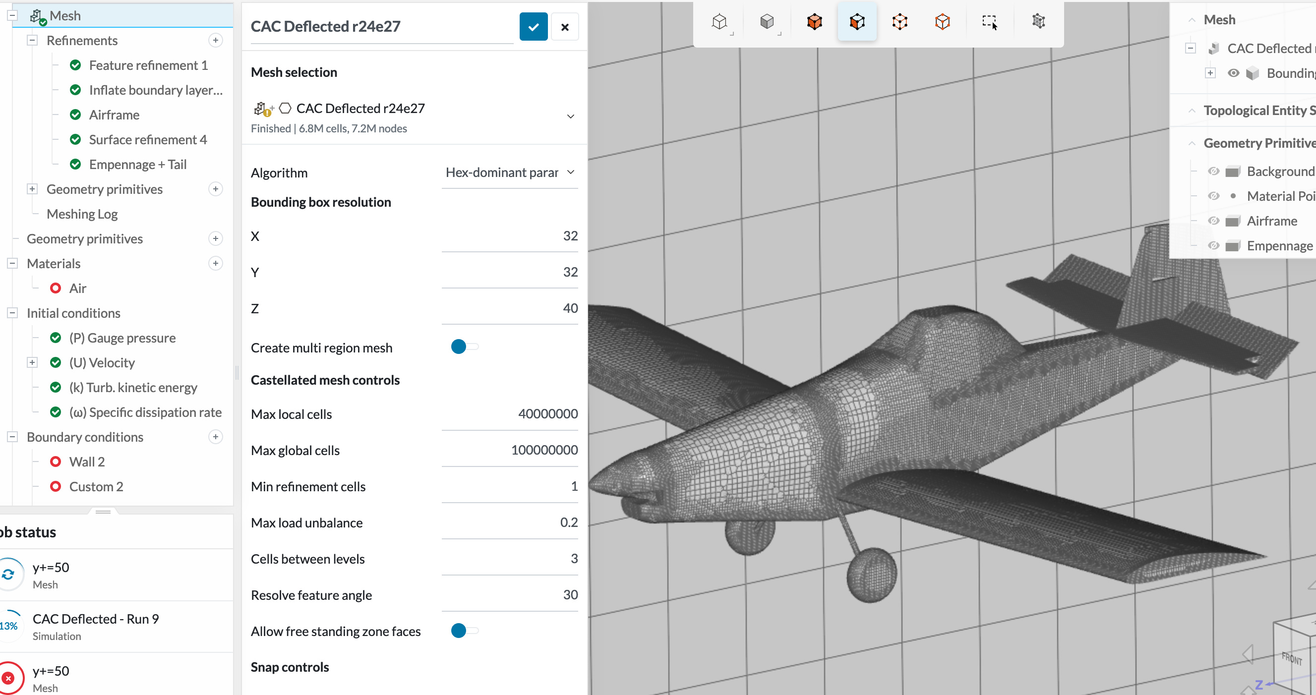
My original mesh, developed using the various refinements recommended in car/truck/plane tutorials and example projects I found in the Public Projects. I included surface refinements, boundary layer inflation, feature refinement, and some detailed flow volumes. Total cells: 6.8MM.

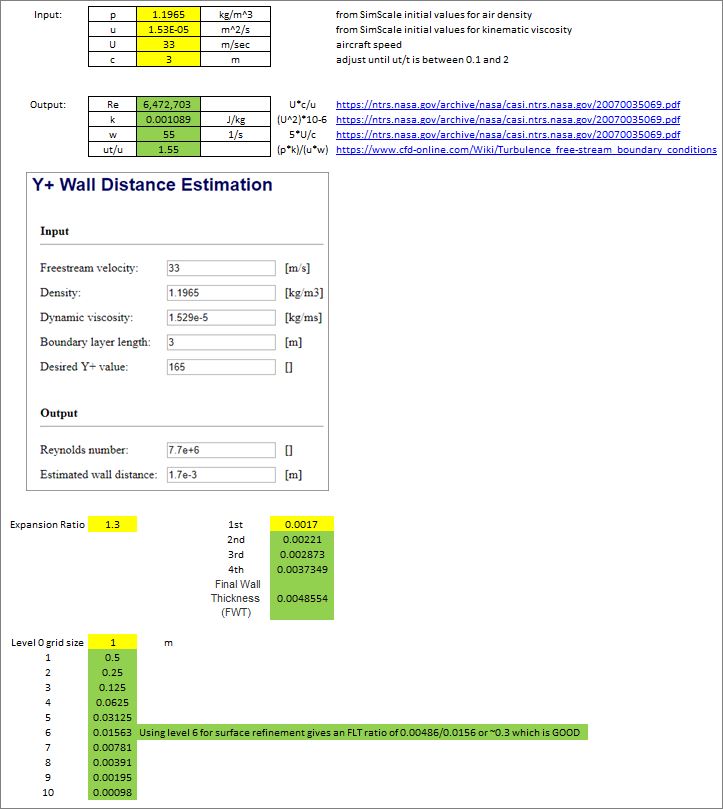
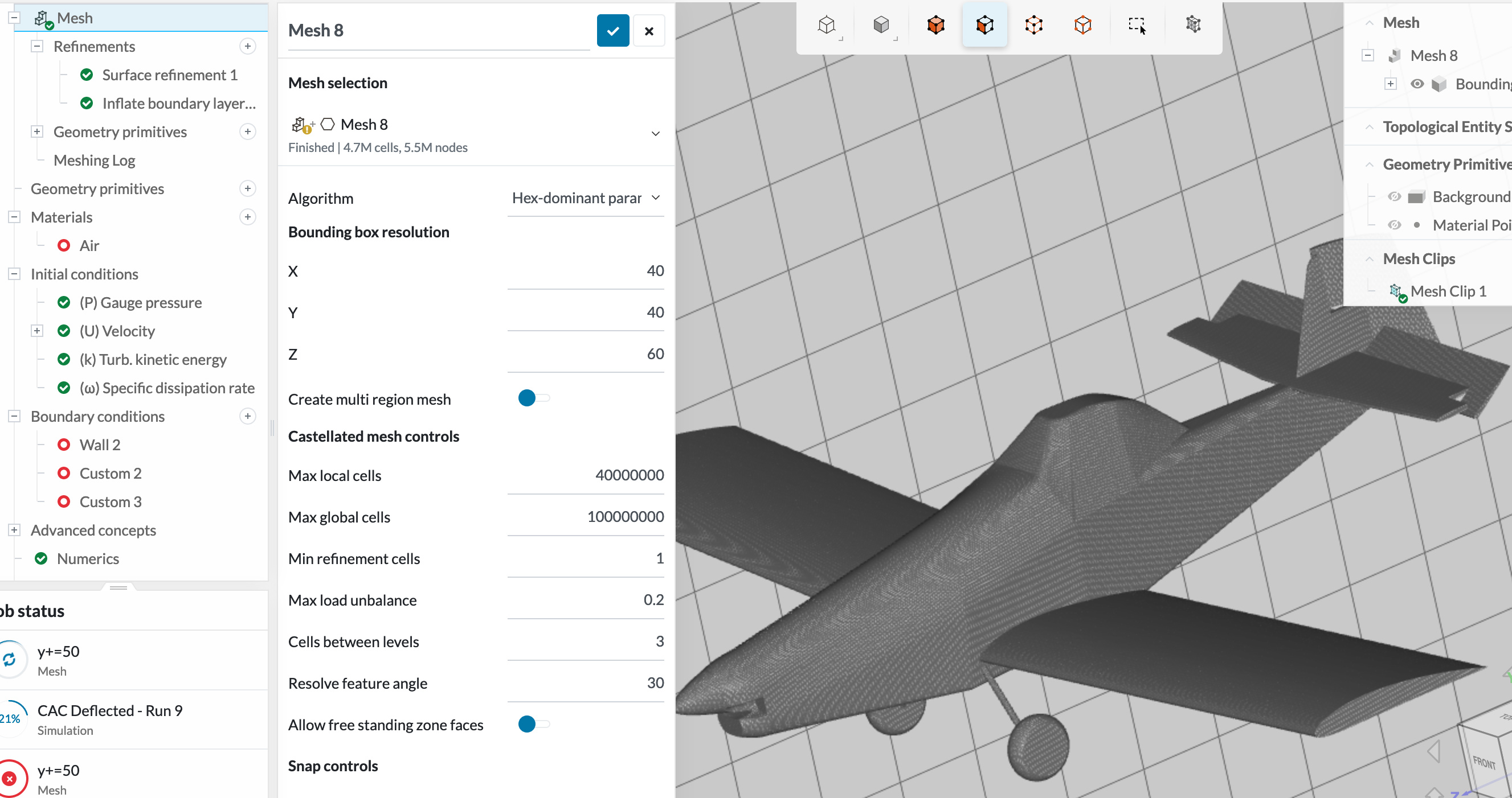
Mesh developed using the Kramer’s Method (oh yeah). Only two refinements: surface and BL inflation. Surface refinement calculated with a target y+ of 165 to be 6 resulted in a nice fine mesh with really good BL coverage (assessing this from the meshing log table). Despite a finer mesh, 4.7MM cells. It’s not how many cells you have, it’s where you put them.

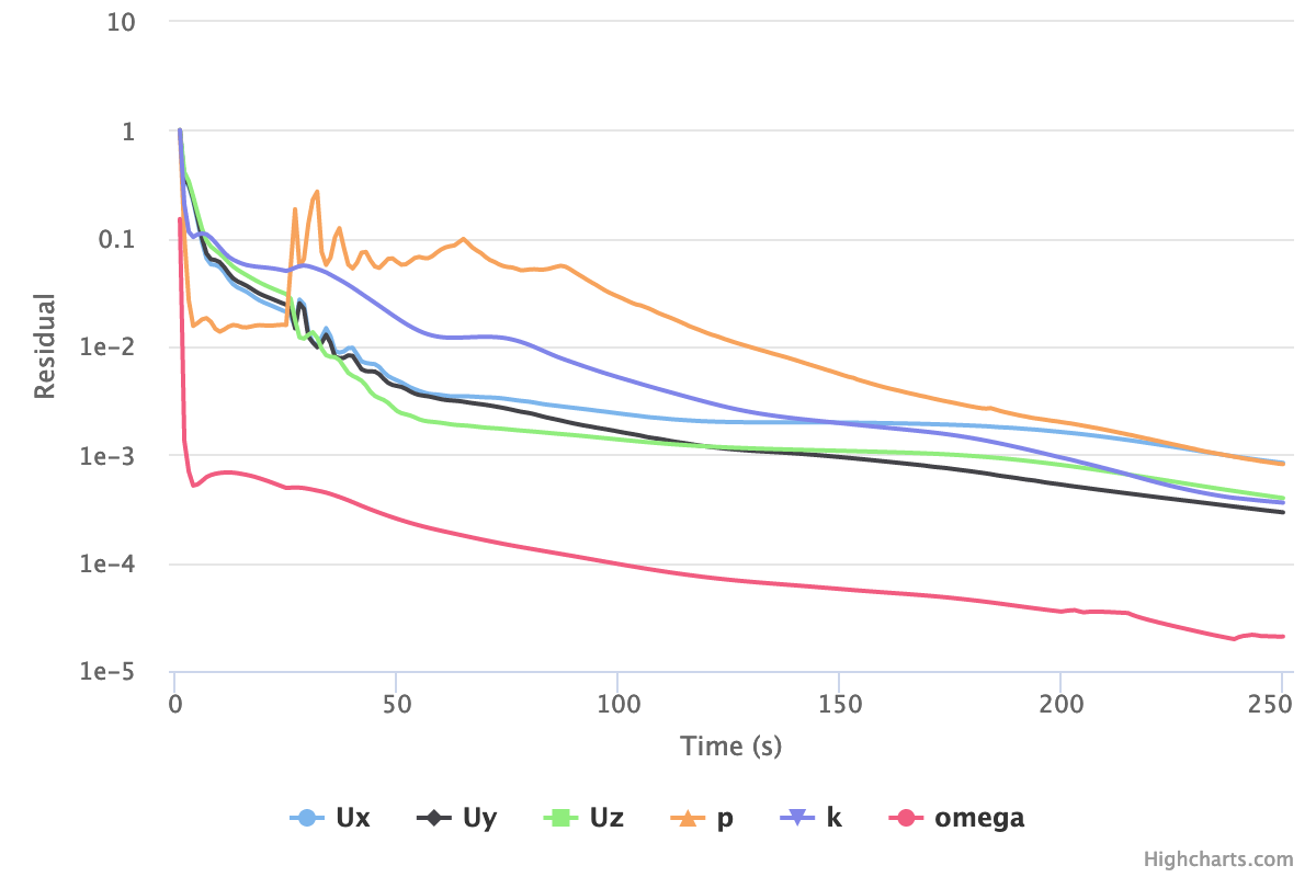
Running identical simulations - velocity ramped over 25s, 1s timestep, the Kramer model converged more quickly. Here is my convergence plot:

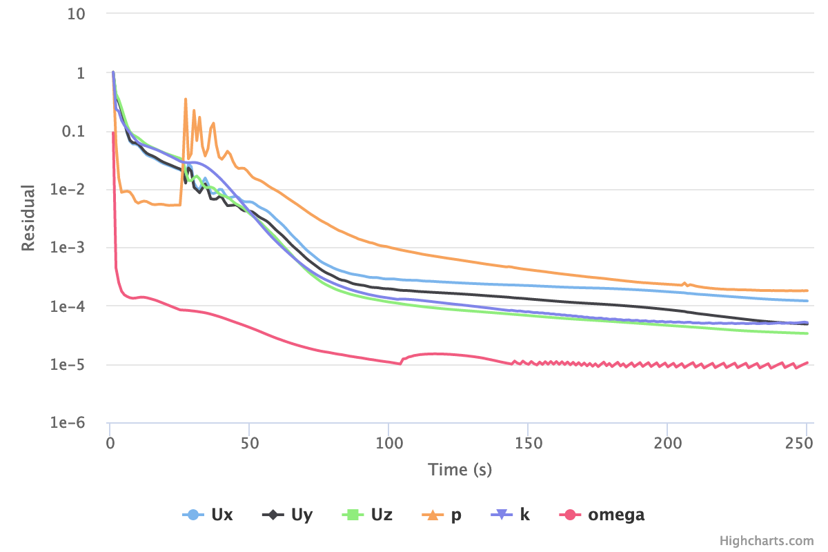
And the Kramer plot:

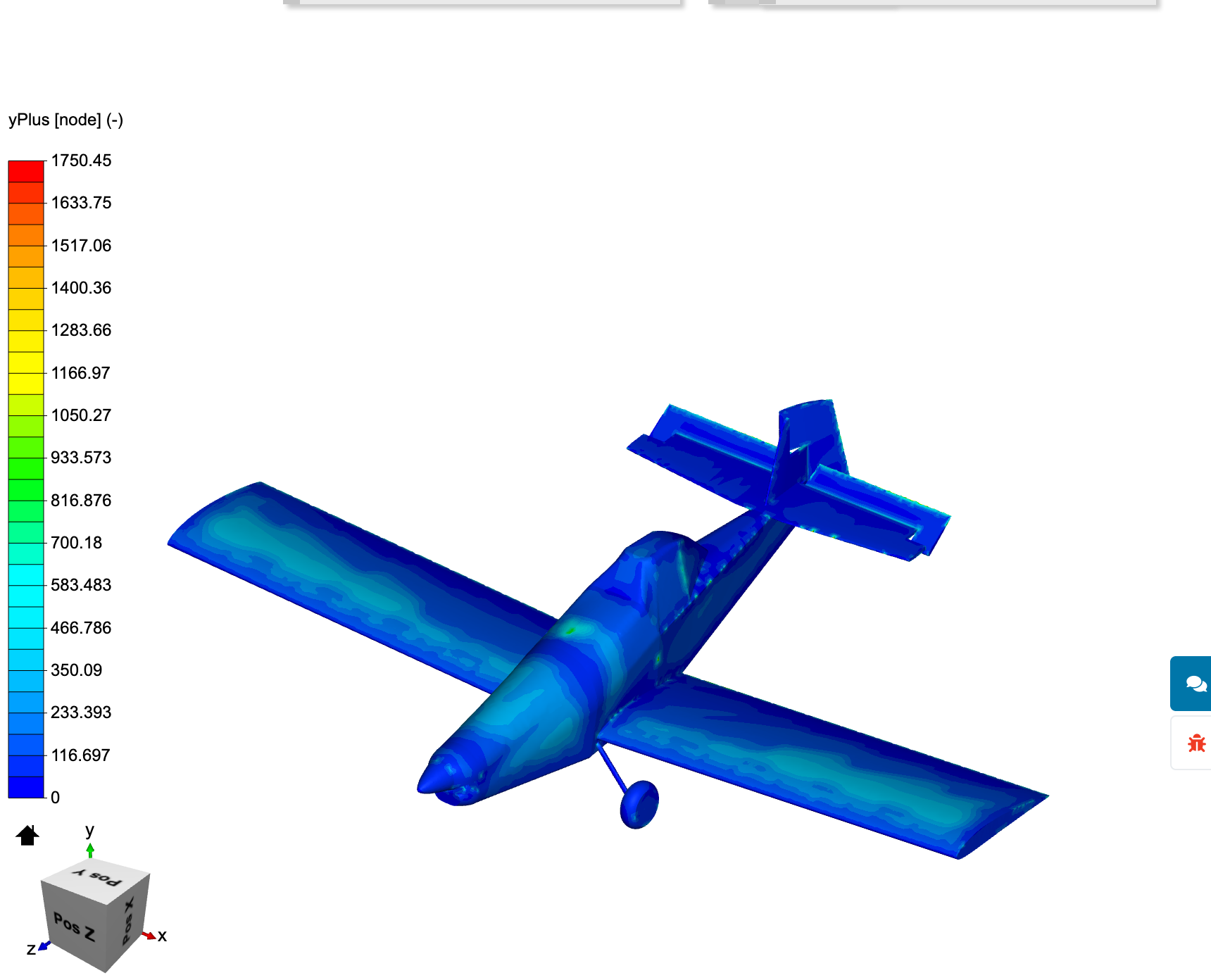
y+ for my model was all over the place, and high:


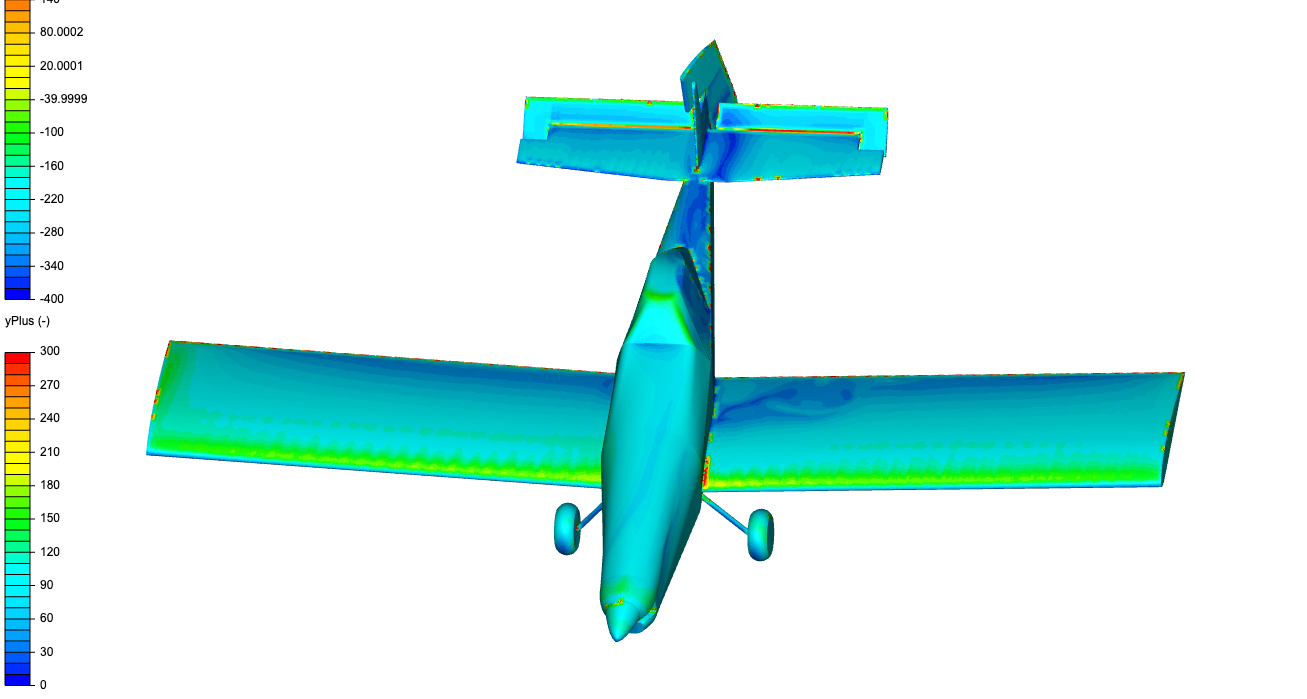
vs Kramer’s (note different scaling):

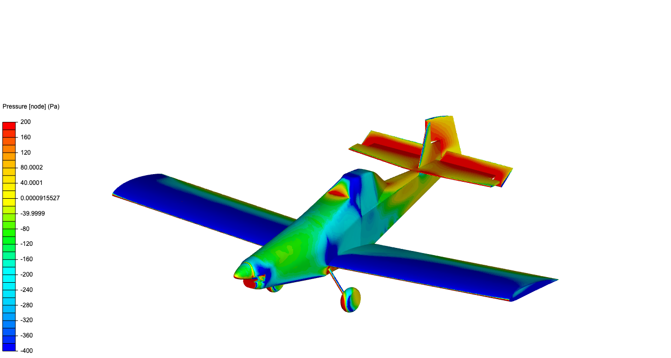
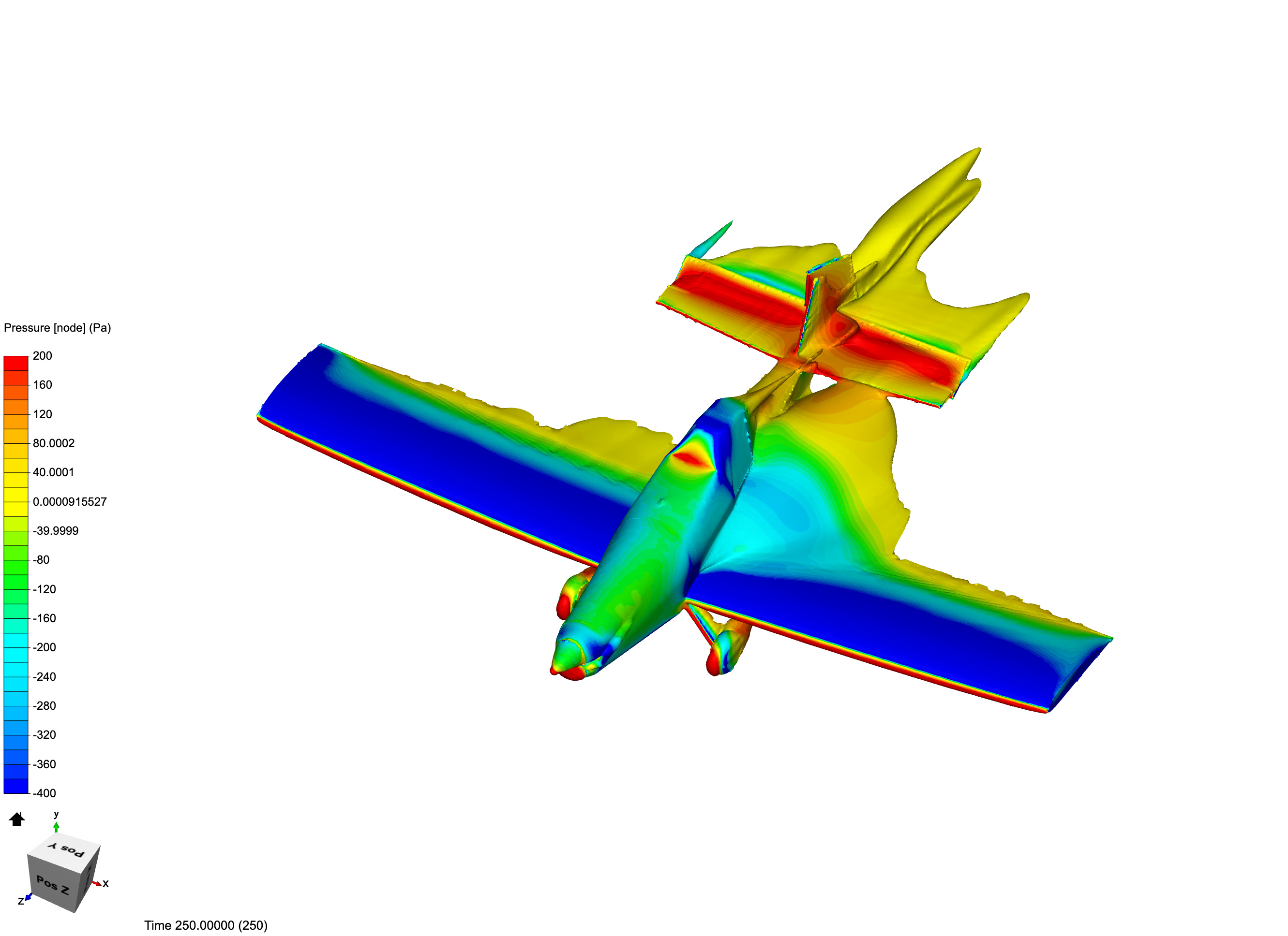
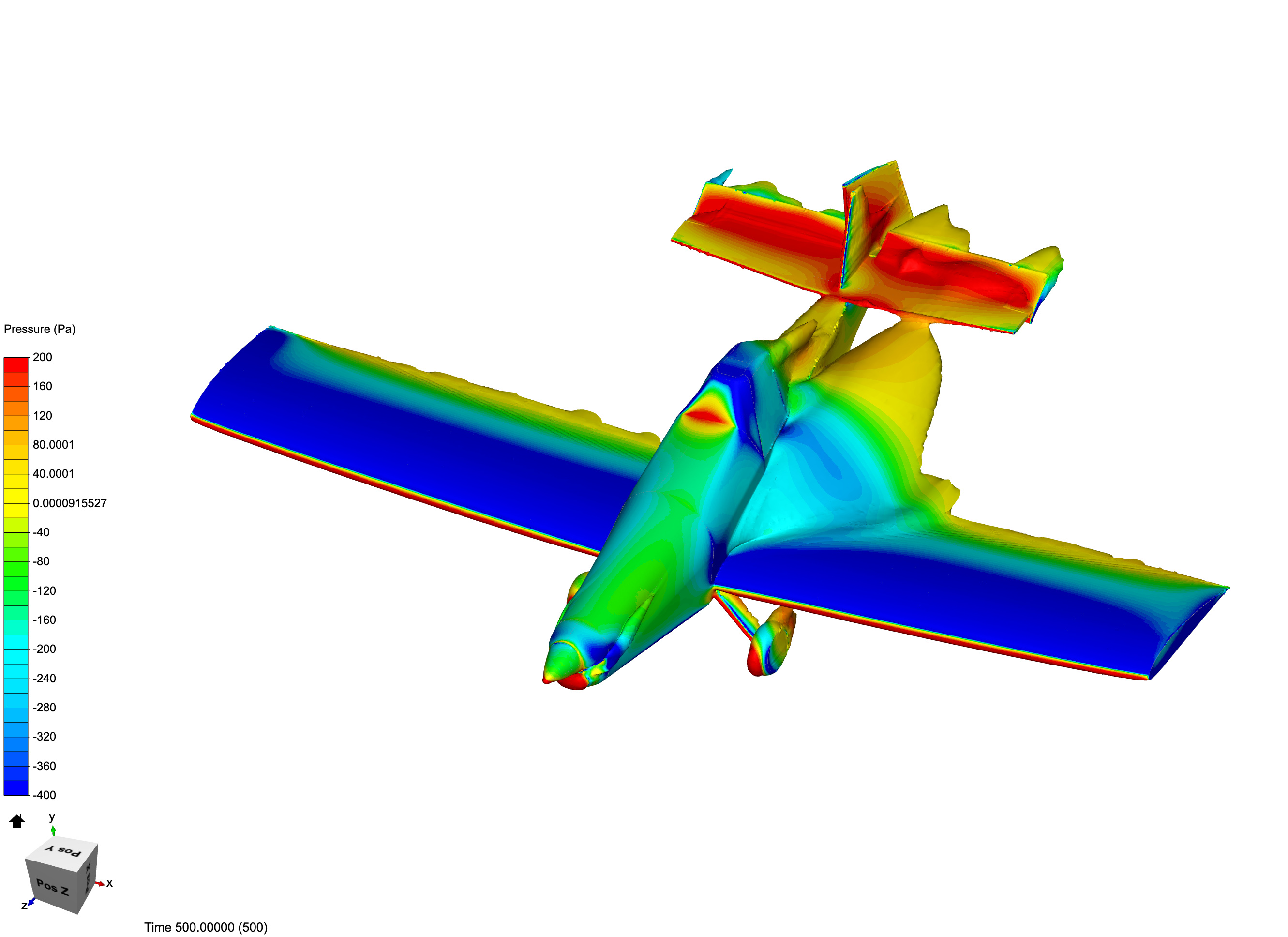
The results speak for themselves. Here’s pressure distribution across the model
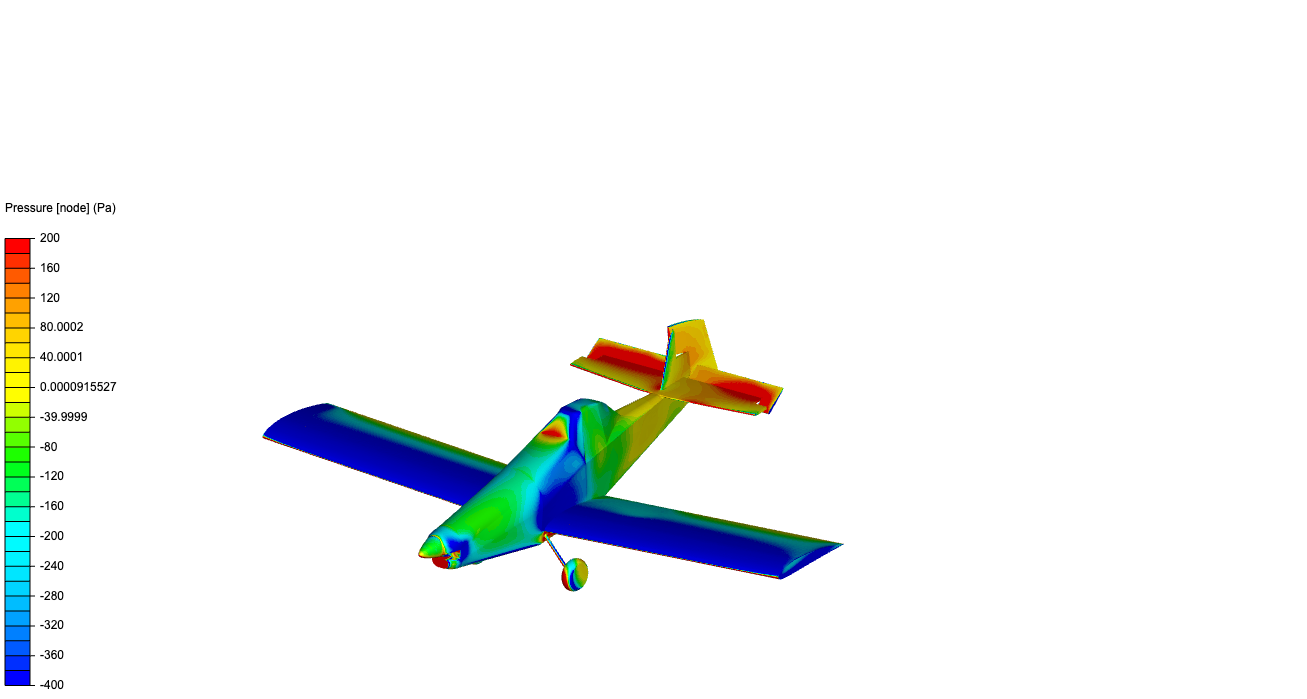

Versus Kramer’s:

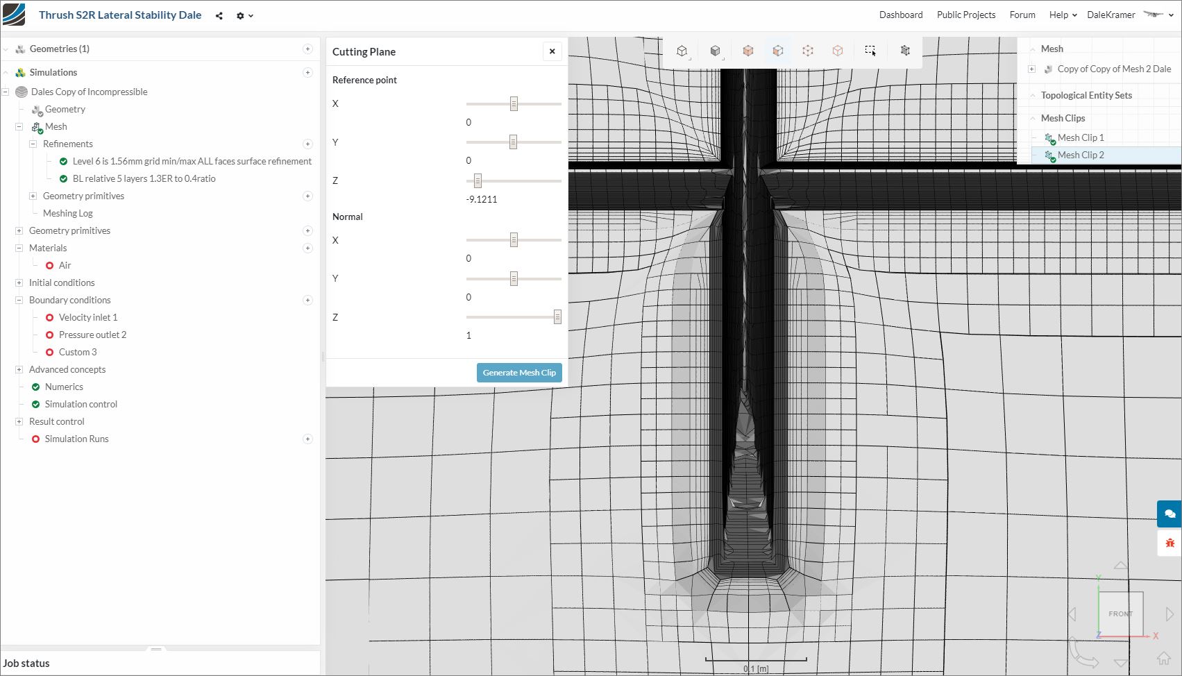
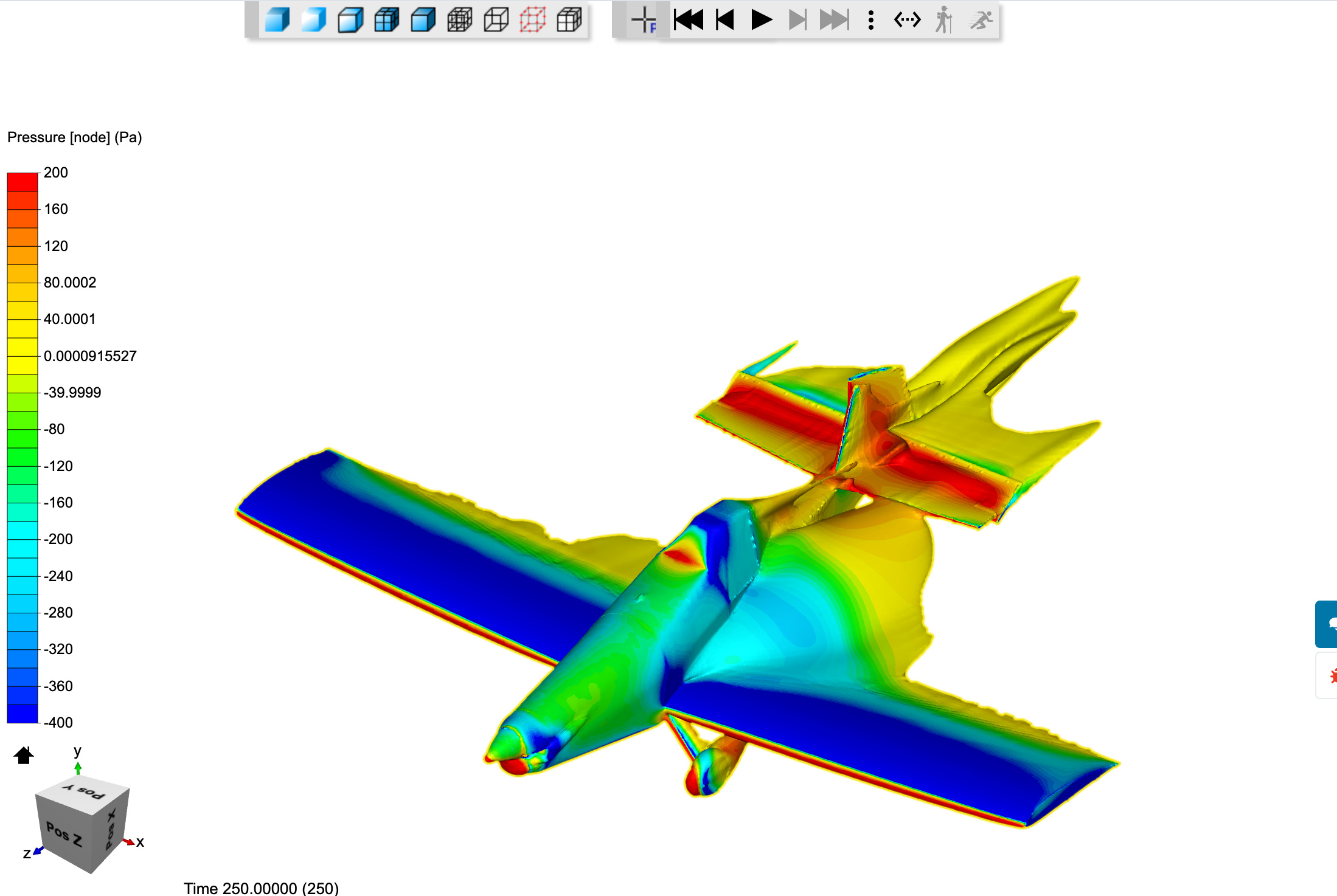
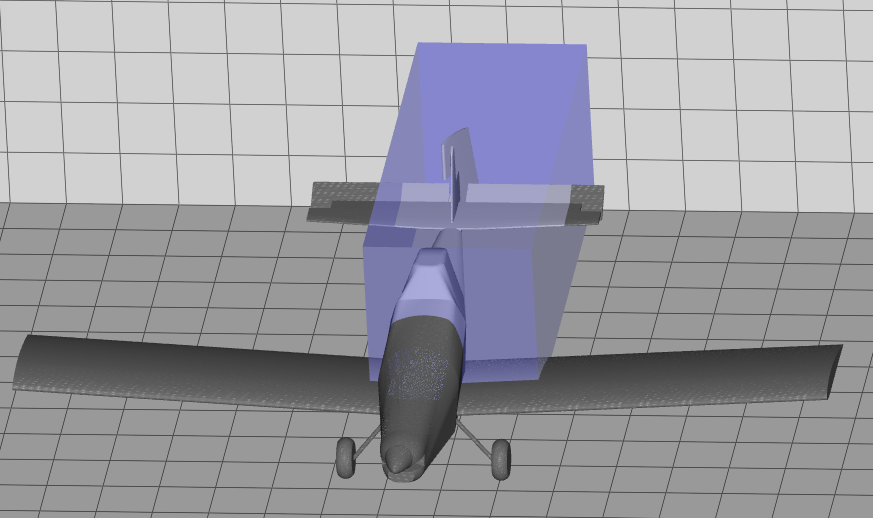
And isovolumes showing ~50% of the freestream velocity and lower. My mesh shows a large recirculation zone beside the fuselage, eventually enveloping the tail midway along the horizontal stabilizer.


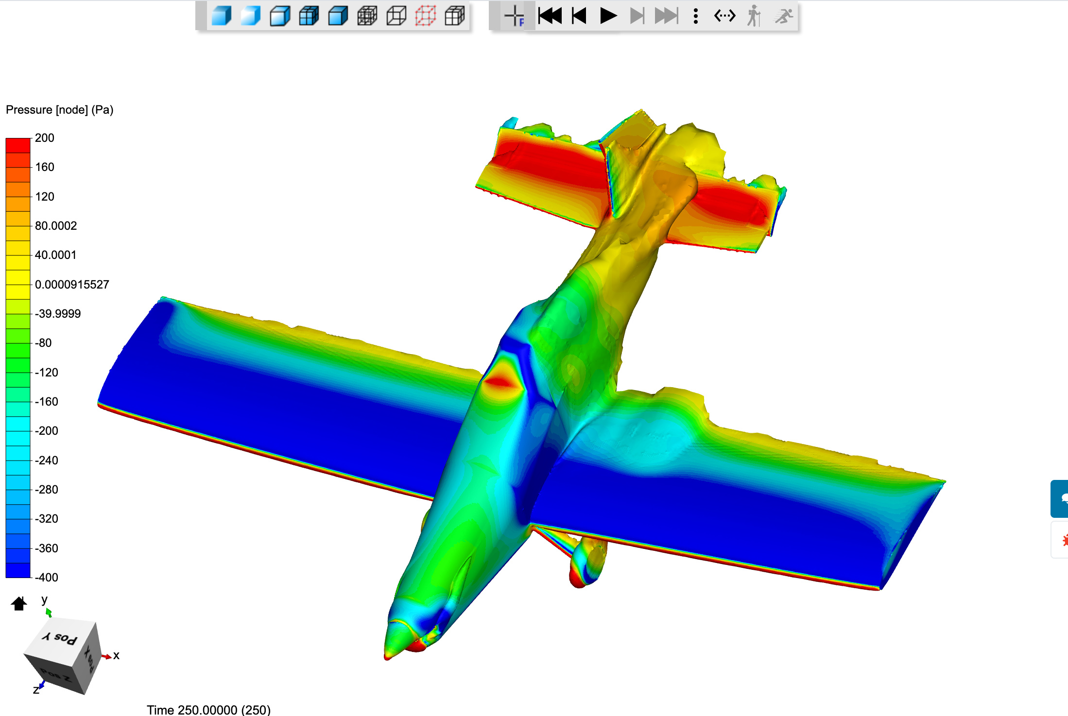
In Kramer’s mesh, we see this zone is almost completely absent. The separation caused by the fuselage instead follows the empennage and connects with the tail much further inboard where we can expect it to have much more of an effect on the rudder. This difference was one of the results that had me really puzzled… in my mesh the rudder still appears to be very effective. In Kramer’s it’s much less so:

Okay that’s what I’ve got… now running out of memory trying to bring the surface refinement up so this might be as good as I can do on 16 cores. Next I’ll add some region refinements to Kramer’s mesh to see if I can smooth out the flow field a bit, but until then - HEED MY WARNING :grin:

EDIT
I went ahead and extended the simulation time of the Kramer BL mesh because I had a feeling that it hadn’t achieved steady-state yet. The result is more in-line with what would be expected… similar flows but probably more accurate with a better BL.
Moments of the poor mesh:


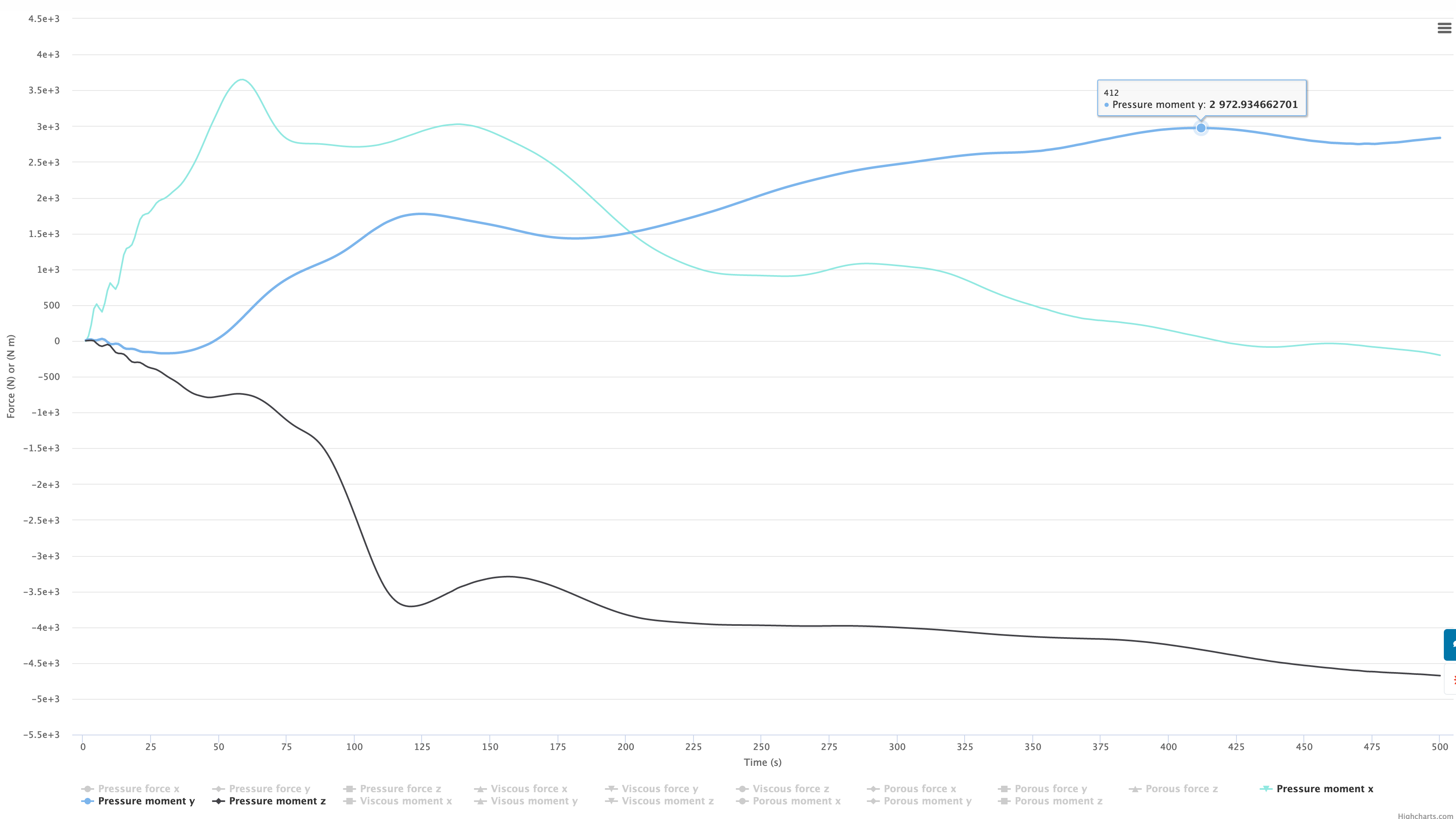
Moments of the Kramer mesh @ 500s:

0-15m/s Z velocity isovolume of the poor mesh:

0-15m/s Z velocity isovolume of the Kramer mesh @ 500s:

2 Likes

You would need to start the process over if you want to change the surface refinement level. As you can see there were quite a few calculations done before we determined that Level 6 was what to use for surface refinement from the conditions that we started with…

With a region refinement you need to look at the granularity of say the pressure profile around and behind the craft by post processing and showing some slices of the volume mesh results. My guidelines for this is stalled until the 2.5% undefined error I found is resolved.

I personally think that proper meshing is about 90% of what separates good and bad CFD results.

Please post a y-plus surface mapping for my interest :wink:

1 Like

Sorry, overlooked that :wink: … Looks good, you can try to lower that 165 to 50 and look at the difference.

Hi everyone,

A custom BC with all parameters set as zero gradient is usable for the sides of the domain. For varying the AOA without needing to re-mesh and re-do the geometry, you can use simple vector notation and apply it as a inlet-outlet BC at the top, bottom, front and rear of the domain. This leaves the sides as “open air” for the custom zero grad BC.

Try it out and see if you can get the flow to behave accordingly. From what I’ve tried before (albeit a long time ago) this works and is a good workaround.

Do note that the same rules still apply in that a sufficiently large Bounding Box is required.

Cheers.

Regards,
Barry

2 Likes

@jousefm, any way to get him some more core power for now so he can complete this very worthwhile project?

This is also a bit of a bump post in case people have not seen the amazing edits @jhartung made to Post #27…

Dale

Thanks for the tag Dale! Will upgrade your account for 1 month @jhartung :slight_smile:

Best,

Jousef

2 Likes

Woah thanks @jousefm! So much power! I’ll report back.

Be careful, using more cores than absolutely needed is VERY core hour wasteful :wink:

2 Likes

Amazing discussion here folks. Really insightful.

2 Likes

Okay @DaleKramer, true to form I threw a bunch more cores at the problem and ended up with a mesh failure (again). What I changed was the addition of a refinement volume of level 6 around the empennage. Having thought a bit about this, it makes sense - a refined volume requires a recalculation of the layer thickness ratio in order to keep the thickness of the BL the same. This begs a question: have you found any way to have refinement regions that don’t encompass the entire model, or are we limited to full-model refinement regions with your method?

I have not had much luck with region boxes that split my model. I think you can enclose the whole model as follows without too many more cells created…

From my personal procedure I am developing re: Un-Optimized Region refinement box:

  1. Create an initial size for a geometry refinement box. I will call this the Geometry Box or GB from now on and specifically the original size as GBorg.
    I have come up with a rather unique way of estimating the size of the GBorg and will start a new topic for discussion on this issue. When that topic has concluded, the results will be summarized here.
    In my case the GBorg turned out to be:
    GBorg

I have never found the need to use the refinement level of the GBorg as fine as the initial surface refinement.

Your surface refinement is Level 6, so my gut says try 4 (5 at the most) for the GBorg refinement level.

So, maybe try level 4 or 5 on your box that splits the model and if that does not help, then try the box that encloses the model as above.

My personal opinion is that the boundary layer thickness and growth should never be relative to the size of the mesh. I always turn off the Layer Size control under Meshing -> Layer adding controls. I honestly wish they would rename that to Relative Layer Size to make it a bit more obvious what this setting does. Now, let me explain my reasoning.

The Y+ calculation is a non-dimensional value that indicates whether viscous or Reynolds stress is more important to the flow.

  • Viscous Dominated: 0 < Y+ < 1 (Full Resolution)
  • Mixed Stresses: 1 < Y+ < 50 (Avoid this region)
  • Reynolds Dominated: 50 < Y+ < 200 (Wall Functions)

When the boundary layer calculations are based on the mesh size, the first layer thickness will change. It is very easy for the layers to fall into the Mixed Stresses region without the user knowledge. In the end, the goal is to fall within either the Full Resolution or Wall Functions layer with your first point from the wall.

I hope this kind of makes sense and helps you figure out your mesh.

1 Like

@DaleKramer okay just to be clear, after defining the GBorg it is necessary to re-do the ratio calculations and decrease the surface refinement level, correct? I’m assuming that the relative layer sizing is with respect to the adjacent mesh. In my case I added a GBorg of 4, reduced the surface refinement to 4, and used a first layer thickness ratio of 0.31.

@LWhitson2 thank you for this excellent (and simple!) definition of Y+. In the case of the “Kramer Method” for using SnappyHexMesh provided in Simscale, we are using relative BL sizing and calculating the proper ratio to size the BL as required. This does have the limitation that it needs to be re-calculated if we change the surrounding mesh. Not knowing the details of the solver, I would expect this to provide some additional flexibility for the solver to resolve geometry problems and NOT throw away our precious BL cells. Maybe I’ll do a spin on this mesh with absolute layer sizing and see how it ends up.

@LWhitson2 All I am saying is that I have had better luck getting Y+ in my desirable range and in having a good gradient of cell size change next to the BL layers with the currently labeled mesh parameter ‘Layer size’ enabled.

I find that having it enabled and using a ratio of 0.3 to 0.4 provides a smooth gradient to the volume meshing outside BL layers. I guess 0.5 would be the ideal ratio as that is the ratio of cell size change between refinement levels but 0.3 to 0.4 seems not too bad a gradient.

Non-dimensional or not, the results are the actual y+ surface mapping and my results seem quite good in that area, do they not?

My memory from my research does not confirm that 1<Y+<50 needs to be avoided, is there some link that you can provide me concerning this ?

@jhartung I believe that the GBorg region refinement should not affect your surface mesh size at level 6 (which mates with the final BL layer). The GBorg refinement simply blends into the surface refinement outside the BL layers.

You are welcome to experiment with absolute layer sizes, it took me a long time to convince myself to try to stay away from them.

Confirmed… when I decreased the surface refinement it simply decreased the surface refinement regardless of the presence of the GBorg.