Very thin boundary layers and y+ on complex geometry

May be a bit early to tell, but it looks like disabling potentialfoam made a big difference.

Yes, wow

@jhartung looks like you are making progress. While potentialFoam is great for reaching convergence, it can cause a few issues of its own.

Looks like pitch and roll moments will take quite a bit longer to stabilize, may have to think about trying the ‘Continue the run’ feature (but won’t take many more core hours for long runs at these settings :slight_smile: ) unless you see another issue here???

Yes, with less than 500 core-hours left I’ve been pondering this. I think it’s time to be an engineer about the problem. My goal is to understand the lateral stability in the airframe with a variety of nose lengths. Looking back on all my simulations, yawing moment has been consistent regardless of all my BL or mesh density shenanigans: around 2800 N-m about my measurement datum. Pitching and rolling moments vary wildly though, so I’m not going to trust those until I do more.

On the positive side I’m getting closer to a full resolution mesh!

That is very nice, how many cells?

Sorry, spoke too soon, did not notice your Y+ scale.

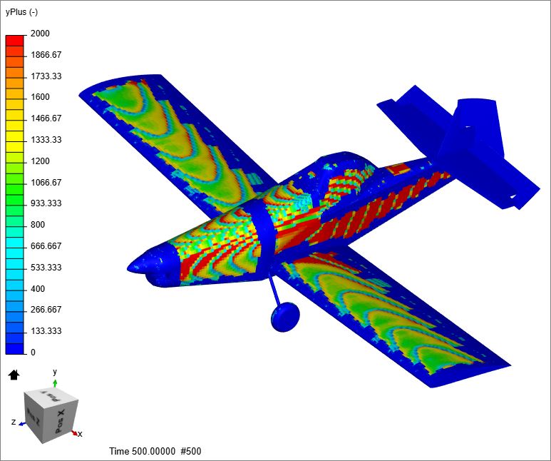
I think this is Run 22 more pertinent Y+ map scaling and it is very confusing to me, did I do it wrong?

Glad that work. I’ll have to thank @1318980 for this suggestion way way back then.

Hi Barry, @Get_Barried

I looked into the ‘body check errors’ more on the geometry we are working with, when I remove the spinner and nose cowl from the plane and re-import that, the ‘body check errors’ disappear.

But the ‘geometry is watertight’ message disappears when I do this.

@jhartung, perhaps you can look into getting a geometry that imports without the ‘body check errors’…

I also had a look at the layering parameters I calculate to determine how good a layering is , using data which I obtain from the the meshing log table. I was hoping you were using that metric in your cat and mouse efforts.

I calculate ‘Average Layers per Face’ and dividing that by the ideal # of layers requested I calculate ‘% of perfect’.

Here they are for your Run22 mesh (top part of chart only):

I am now less confused with the Y+ mapping I shown here (and the previous one is likely similar too)… 47% is not very good…

I am running a 64 core on the 69% perfect 25.6M mesh now, but I do not have much hope for it. I like to see in the 90% perfect range…

I think it is time for a MK4 project :wink: , start with geometry that has no ‘body check errors’ and is watertight.

While you are doing geometry ops, try to get rid of as many faces in the geometry that had zero layers made on them in the mesh log, they are very small in one direction at least (you could layer them but you would have to surface refine them to a much higher level… Every time you have a deflation at a small face it takes a great surface distance away from that face to get back to 12 layers, which is likely the cause of losing such a high % of perfect for you…

Hi Josh!

Added 3,000 more to your account for your investigations, also extended your academic licence. At the end we want to summarize everything and create a guide out of it if possible :slight_smile:

Best,

Jousef

I see I may have created a monster here. While it is amazing you are striving for a pure y^+ < 1 mesh, please remember that this only matters for areas where determining the the separation point is absolutely critical. For example, a NACA 0012 at flat and level has no flow separation and therefore you don’t need such a strict y^+; however, if you wanted to find the exact stall point by doing successive simulations then the separation is critical and y^+ \leq 1 is absolutely necessary.

I’m guessing for the majority of your plane that a higher y^+ will be adequate but areas that are really important to separation should be refined. Does that make sense?

1 Like

Yes, but I assume that the wing will have separated well in front of the trailing edge and that the side of the fuselage will have separated somewhere and both of those areas are not anywhere near Y+=1. (in fact Y+ seems to be measured in the 1000’s there).

I think both areas mentioned will surely have an effect on rudder blanketing.

I assume that in order to know where separation lines exist, that the boundary layer must be modeled properly everywhere…

I too have seen the great variations in moments between different y+ results and have been very confused with that since forces seem to vary little with different y+ results . I am hoping perseverance here will lead to better understanding on my part from my weird perspective :wink:

And we have not even looked at EVR plots yet :wink:

@DaleKramer I think the hardest part is that we, me included, like to bite off a large chunk without understanding the overall complexity. We all see these really cool looking simulations on SimScale (F1 car, fighter jets, our favorite roadster) and the pictures all pass the eye test. Sure, the streamlines look somewhat right and the scalar plots are passable, but most of the simulations you see are just not correct.

Take my study of a Pinewood Derby car as a perfect example. It’s a block of wood with four cylindrical tires, how hard can it be. You saw the first part of just studying the wall bounded flow over a rectangular body. There is a lot to unpack there and we haven’t even started the complicated part.

@jhartung I applaud you for sticking with it to get the correct answer, not just a cool looking answer. I would advise you to possibly take a small step back and run some individual pieces of your simulation to determine what mesh resolution you need. Do you really need to worry about separation on the body? Are you running a high enough AoA that the wing flow separates? Some simple 2D runs would help answer those questions and give you a better idea on mesh and spacing for each part. Yes, it will take a lot longer to finish, but you don’t just want an answer, you want the right answer. Just my two cents.

2 Likes

But I assumed that had been done after I saw the isovolume plots way back here where it appeared that the flow separated from the fuselage and from the fact that I think rudder blanketing issues are really only a concern after a stall. Also the input vector of the air is quite high AOA with side angle… So even just looking at it now, I would expect separation potential in both areas.

But you know what they say about assuming :wink:

YOU ARE SOOOO CORRECT!

:rofl::rofl::rofl::rofl::rofl::rofl: More like fed a monster

Ah, this is much better and we begin to have oscillatory convergence of moments on all 3 axes (sim run of 25.6M mesh took 290 core hrs on 64 cores) :smile:

Thrush-U

And for 172 more core hours we continued (LOVE THAT NEW FEATURE :smiley::smiley: )that sim run to 1500s and have this:

Now someone has to try some EVR plots :pray: :pray: :pray: for volunteers… (no more core hours needed to make them :wink: )

1 Like

@DaleKramer @LWhitson2 @Get_Barried @jousefm I can’t thank you all enough for your help on this. I as well have felt I’ve created a monster and there has been plenty of facepalming, especially at Dale’s late night posts in which he invalidates all the progress I think I’ve made for a week with a simple observation. I feel like I’m taking a numerical approach to a Master’s in fluid simulation here - step by step with not all of them forward. Regardless, it’s been a lot of fun.

As @LWhitson2 has observed, I’m clearly taking too large a bite here. I probably also have ill-defined goals, unless my primary goal is to “learn more about CFD”. In my earlier post I said it’s time for me to be an engineer (rather than a scientist) about this. In fact I have two goals:

  1. Assess yawing moment of the aircraft due to different length noses.
  2. Assess tail effectiveness at high yaw/AOA and try different solutions to improve it (dorsal, ventral, VGs, etc).

Initially I saw CFD as a “silver bullet” to take care of all these goals at once in a single elegant simulation. With some experience under my belt I understand this may be possible but is inefficient.

So with respect to goal 1, I think I can even use a wall-function simulation to test this as long as I ignore pitch and roll results. From the Dale’s monster run on my 25MM node mesh, I’m seeing what I saw in pretty much every other solution: y moment converging about 2800 N-m , y and z moments all over the place (sim to sim). This is at least a clumsy version of a mesh invariant result, so it seems it can be trusted.

With respect to goal 2, this may require a full-resolution run in order to have fully developed turbulent flow from the fuselage blanking hitting the tail. @DaleKramer there are two problems here: a tendency toward rudder lock and stalling of the horizontal tail. What is NOT factored in to this sim and is very important are effects of a HUGE 108" prop. I think it’s probably worth moving that effort to a completely separate project and pursuing with the power of 64 cores available.

2 Likes

That was my first question that I bit my tongue on when I saw this topic appear (and at what RPM…). I did not want to scare you off as I knew we needed to start without it first…

Actually if the rudder locked and/or the horizontal stab stalled, they would likely show up in moments here.

Do you know conditions that actual rudder lock or hstab stall occurs at (AOA, airspeed etc) :question:

Is the total lift we see anywhere near the flying weight of the aircraft or are we in parachute mode :wink: :question:

But the y and z moments are basically oscillatory stable on the 25.6M run, you can see this better in the 1500s continuation I am about to add to my above post.

WOW, now that is incentive enough to persevere… :wink:

Okay new geometry is greatly simplified and watertight. It’s the last four STEPs in there starting with 510G. Per your comment about faces with 0 layers, I’m guessing many of those are the faces that are coincident with other bodies… probably a byproduct of doing “select all visible”. Do you actually select individual faces?

EDIT
510G model is a good example.

You almost have to use select all when you have 150+ faces :wink: , but if you select volumes from geometry, you don’t see those faces…
Problem is that you have to be darn sure you need all 150+ of those faces are needed in the mesh.
If those faces are very small in one direction, then I question their need in the geometry file considering what havoc they play when layering and deflations.
So, I do not think a byproduct of ‘select all visible’ but more accurately, that is what is in the CAD file itself.

Would be much easier to hyperlink to them…

1 Like

Edited previous post with a link to a good one. The model is an assembly in Solidworks so when I export it comes out as a bunch of solids which contain coincident faces where they mate up. I can unselect things like the end of the wings coincident with the fuselage but that still leaves a face on the fuselage side. Is there a file format that you’re aware of that will boolean the whole thing to eliminate those or should I boolean in Solidworks prior to export (PITA)?