@DaleKramer I think the hardest part is that we, me included, like to bite off a large chunk without understanding the overall complexity. We all see these really cool looking simulations on SimScale (F1 car, fighter jets, our favorite roadster) and the pictures all pass the eye test. Sure, the streamlines look somewhat right and the scalar plots are passable, but most of the simulations you see are just not correct.
Take my study of a Pinewood Derby car as a perfect example. It’s a block of wood with four cylindrical tires, how hard can it be. You saw the first part of just studying the wall bounded flow over a rectangular body. There is a lot to unpack there and we haven’t even started the complicated part.
@jhartung I applaud you for sticking with it to get the correct answer, not just a cool looking answer. I would advise you to possibly take a small step back and run some individual pieces of your simulation to determine what mesh resolution you need. Do you really need to worry about separation on the body? Are you running a high enough AoA that the wing flow separates? Some simple 2D runs would help answer those questions and give you a better idea on mesh and spacing for each part. Yes, it will take a lot longer to finish, but you don’t just want an answer, you want the right answer. Just my two cents.
But I assumed that had been done after I saw the isovolume plots way back here where it appeared that the flow separated from the fuselage and from the fact that I think rudder blanketing issues are really only a concern after a stall. Also the input vector of the air is quite high AOA with side angle… So even just looking at it now, I would expect separation potential in both areas.
@DaleKramer@LWhitson2@Get_Barried@jousefm I can’t thank you all enough for your help on this. I as well have felt I’ve created a monster and there has been plenty of facepalming, especially at Dale’s late night posts in which he invalidates all the progress I think I’ve made for a week with a simple observation. I feel like I’m taking a numerical approach to a Master’s in fluid simulation here - step by step with not all of them forward. Regardless, it’s been a lot of fun.
As @LWhitson2 has observed, I’m clearly taking too large a bite here. I probably also have ill-defined goals, unless my primary goal is to “learn more about CFD”. In my earlier post I said it’s time for me to be an engineer (rather than a scientist) about this. In fact I have two goals:
Assess yawing moment of the aircraft due to different length noses.
Assess tail effectiveness at high yaw/AOA and try different solutions to improve it (dorsal, ventral, VGs, etc).
Initially I saw CFD as a “silver bullet” to take care of all these goals at once in a single elegant simulation. With some experience under my belt I understand this may be possible but is inefficient.
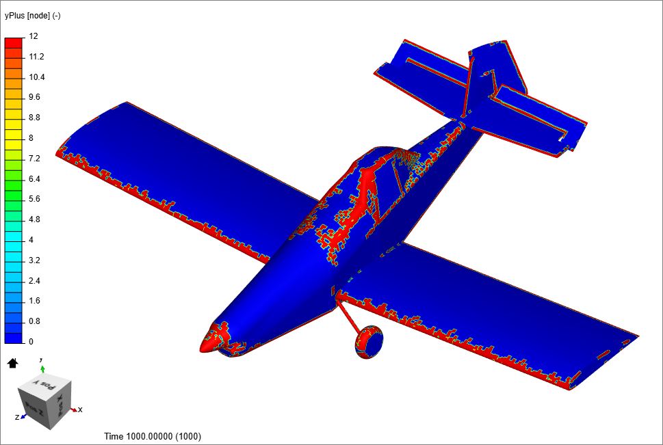
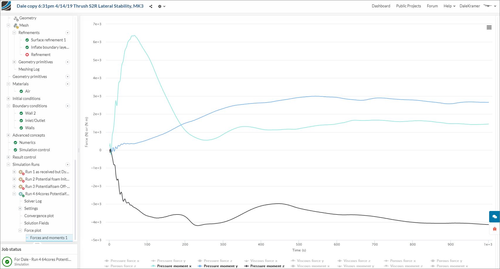
So with respect to goal 1, I think I can even use a wall-function simulation to test this as long as I ignore pitch and roll results. From the Dale’s monster run on my 25MM node mesh, I’m seeing what I saw in pretty much every other solution: y moment converging about 2800 N-m , y and z moments all over the place (sim to sim). This is at least a clumsy version of a mesh invariant result, so it seems it can be trusted.
With respect to goal 2, this may require a full-resolution run in order to have fully developed turbulent flow from the fuselage blanking hitting the tail. @DaleKramer there are two problems here: a tendency toward rudder lock and stalling of the horizontal tail. What is NOT factored in to this sim and is very important are effects of a HUGE 108" prop. I think it’s probably worth moving that effort to a completely separate project and pursuing with the power of 64 cores available.
That was my first question that I bit my tongue on when I saw this topic appear (and at what RPM…). I did not want to scare you off as I knew we needed to start without it first…
Actually if the rudder locked and/or the horizontal stab stalled, they would likely show up in moments here.
Do you know conditions that actual rudder lock or hstab stall occurs at (AOA, airspeed etc)
Is the total lift we see anywhere near the flying weight of the aircraft or are we in parachute mode
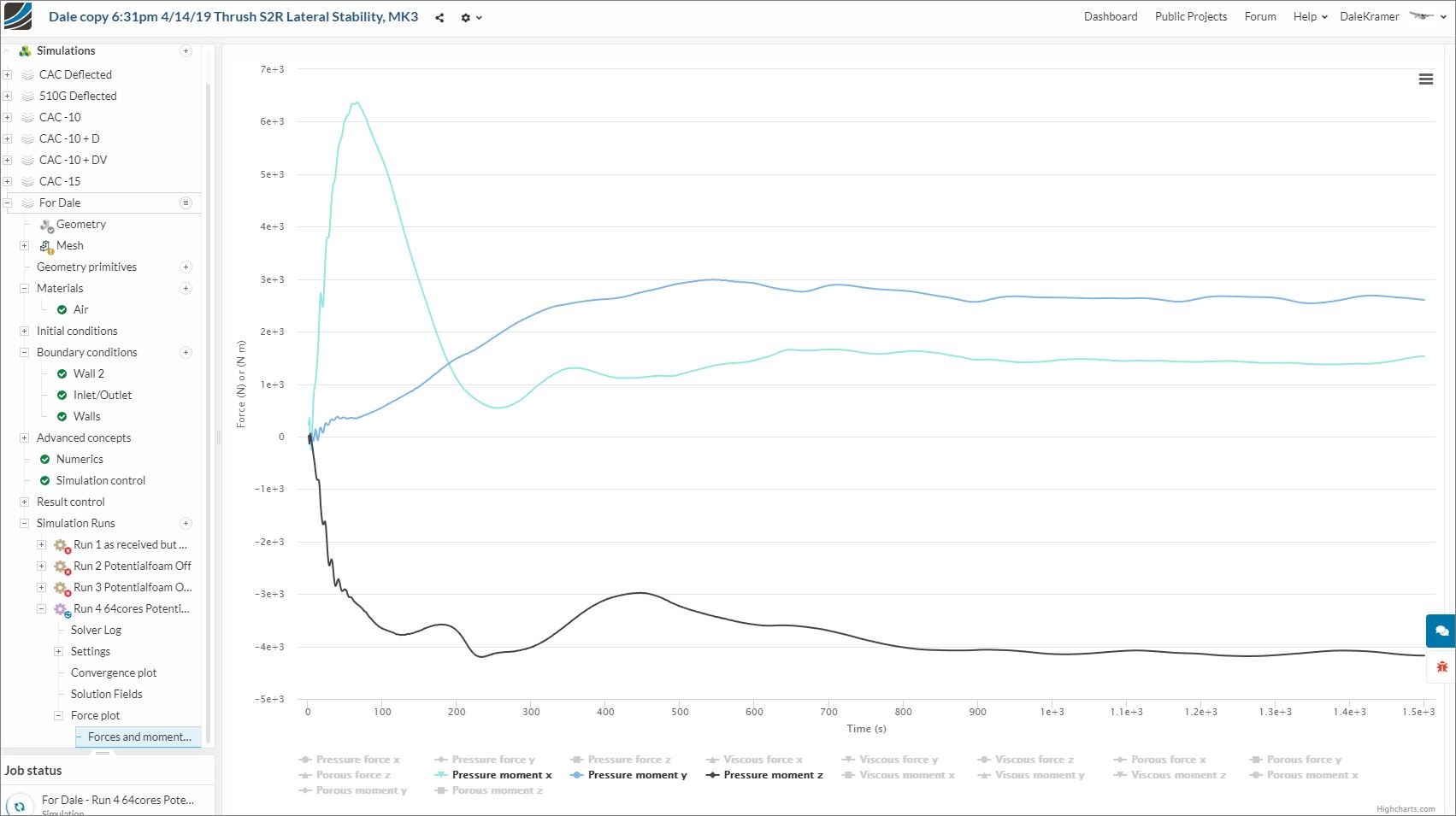
But the y and z moments are basically oscillatory stable on the 25.6M run, you can see this better in the 1500s continuation I am about to add to my above post.
Okay new geometry is greatly simplified and watertight. It’s the last four STEPs in there starting with 510G. Per your comment about faces with 0 layers, I’m guessing many of those are the faces that are coincident with other bodies… probably a byproduct of doing “select all visible”. Do you actually select individual faces?
You almost have to use select all when you have 150+ faces , but if you select volumes from geometry, you don’t see those faces…
Problem is that you have to be darn sure you need all 150+ of those faces are needed in the mesh.
If those faces are very small in one direction, then I question their need in the geometry file considering what havoc they play when layering and deflations.
So, I do not think a byproduct of ‘select all visible’ but more accurately, that is what is in the CAD file itself.
Edited previous post with a link to a good one. The model is an assembly in Solidworks so when I export it comes out as a bunch of solids which contain coincident faces where they mate up. I can unselect things like the end of the wings coincident with the fuselage but that still leaves a face on the fuselage side. Is there a file format that you’re aware of that will boolean the whole thing to eliminate those or should I boolean in Solidworks prior to export (PITA)?
Actually, I booleaned together, very easily, a lot of your model (after exploding them somewhat) in Rhino and that is how I found that nose cowl problem. The nose cowl did not boolean with aft fuselage.
I really like Rhino for things like this and I always import Rhino .3dm files to SimScale. I think it is very similar format to STL (maybe an extension of STL) but that is only my feeling without any way to confirm that.
Unless I have a specific reason not to, I import my aircraft as 1 watertight solid…
Better to find the problems in CAD than bring it into SimScale and hope SimScale can fix less than perfect CAD geometries.
Vexing. The Solidworks model is clean and beautiful. Coincident surfaces wherever there should be. I tried an STL export and it’s apparently not watertight either.
Well currently not one is watertight and it seems to be due to the fact that Solidworks sucks at complex surfaces… took it into Rhino and found multiple meshing errors. But this one is as close as it gets.
I played few minutes with free Autodesk MeshMixer (only STL) and it has set of optons for repairing meshes. Target user are 3D printing guys, trying to make sens of their 3D scans.
EDIT: I guess you saw that answer this morning (what a great system we have here and comforting to know that real masters are lurking when really needed), all solids are considered watertight and the need for that message apparently disappeared, I still would like to see it there…
Before I discovered that issue, I started playing with your CAD files, I found a couple naked edges in Rhino, even though the spinner Booleaned to the ‘cowl’ I saw that somehow the rear spinner plate was still in the solid. Then I saw that the tip of the nodes in the spinner’s curve of revolution caused the spinner to have a concave nose (likely does not matter) and that the spinner centerline was not on the x-axis by ~.8" so model could not left/right symmetrical. Fixing all that did not help but I did anyway. Never ended up getting cowl to Boolean with rear fuselage, not seem to be lofted from same curve I guess.
I guess none of that matters to watertight issue, just thought I would pass along those minor points…
NOW, to move on, I guess someone should make those EVR plots on the successful 25.6M simulation and then make further decisions on mesh refinements for MK4 project. ing for a volunteer who knows Paraview to rescue me …
Thank you so much for that other topic… I was pulling my hair out trying to figure out how to get it to be watertight. There really aren’t many knobs in Solidworks to tweak if the geometry in the model is well defined but there are still errors on export.
You’re seeing the thrust vector offset of the engine modeled both unnecessarily and poorly in this case. Knowing what I know now I would omit this geometric detail and save some pain.
I’m wondering: other than your cute little table for layer %, do you ever use the added cells percentage as a measure of quality? For instance, here’s one that layered up pretty well (Y+ about 125, so using wall functions… much more consistent than full res BLs)
Detected 0 illegal faces (concave, zero area or negative cell pyramid volume)
Extruding 473080 out of 475489 faces (99.493363674%). Removed extrusion at 0 faces.
Added 3631913 out of 3803912 cells (95.4783654301%).
That 95% added seemed to be a fair measure of retained BL cells, so I was using it. By comparison, my best full res layering attempts (using the modified Kramer method with absolute BL definition and variable surface refinement) yielded around 72%.